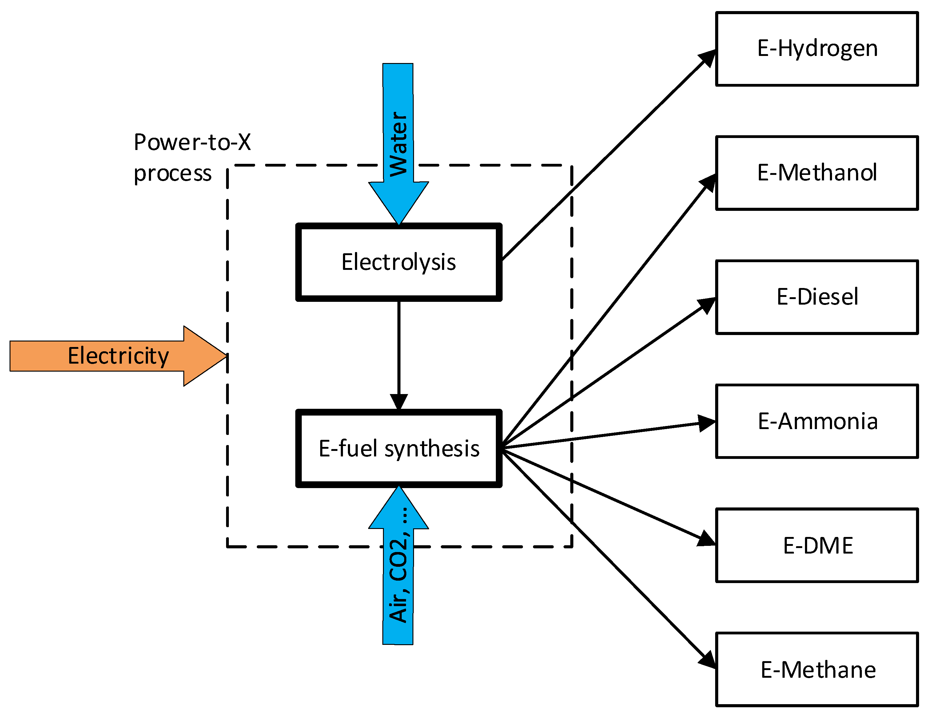
Power-to-X (PtX) are fuel production pathways in which electricity is converted into various gaseous or liquid fuels, such as e-hydrogen, e-methanol, e-methane, dimethyl ether (E-DME), e-ammonia, or e-diesel. These fuels are also named electrofuels (e-fuel) or power-to-liquid (PtL) and are mentioned in the Annexes of the RED II amendments as alternative options for the decarbonisation of the transport sector. Some of these molecules still contain carbon atoms, thus producing CO2 when used for energy production. The carbon source for the synthesis of e-fuels has to be carefully analysed to define them really carbon neutral.
1. Introduction
The PtX process consists of a change of energy vector: electricity is converted to different molecules that store energy in chemical form (Figure 1). Obviously, this process has an efficiency lower than 1 (defined as the ratio between the lower heating value of the e-fuel produced and electrical energy consumed, see Equation (1)) but converts electrical energy into a different form that could be easily stored compared to electricity.
Figure 1. E-fuels production pathways.
E-fuel production and use should be carefully assessed because they could have negative impacts on the GHG emissions of the energy system. A fair evaluation cannot ignore the analysis of the whole system’s load and generation: Only an excess of electricity (generated by nondispatchable renewable sources) is really CO
2-neutral; in all other moments, electricity brings itself a CO
2-equivalent amount
[1].
Water electrolysis is the fundamental process to convert electrical energy to a chemical one with the production of e-hydrogen, and it is also the first step of all considered PtX pathways.
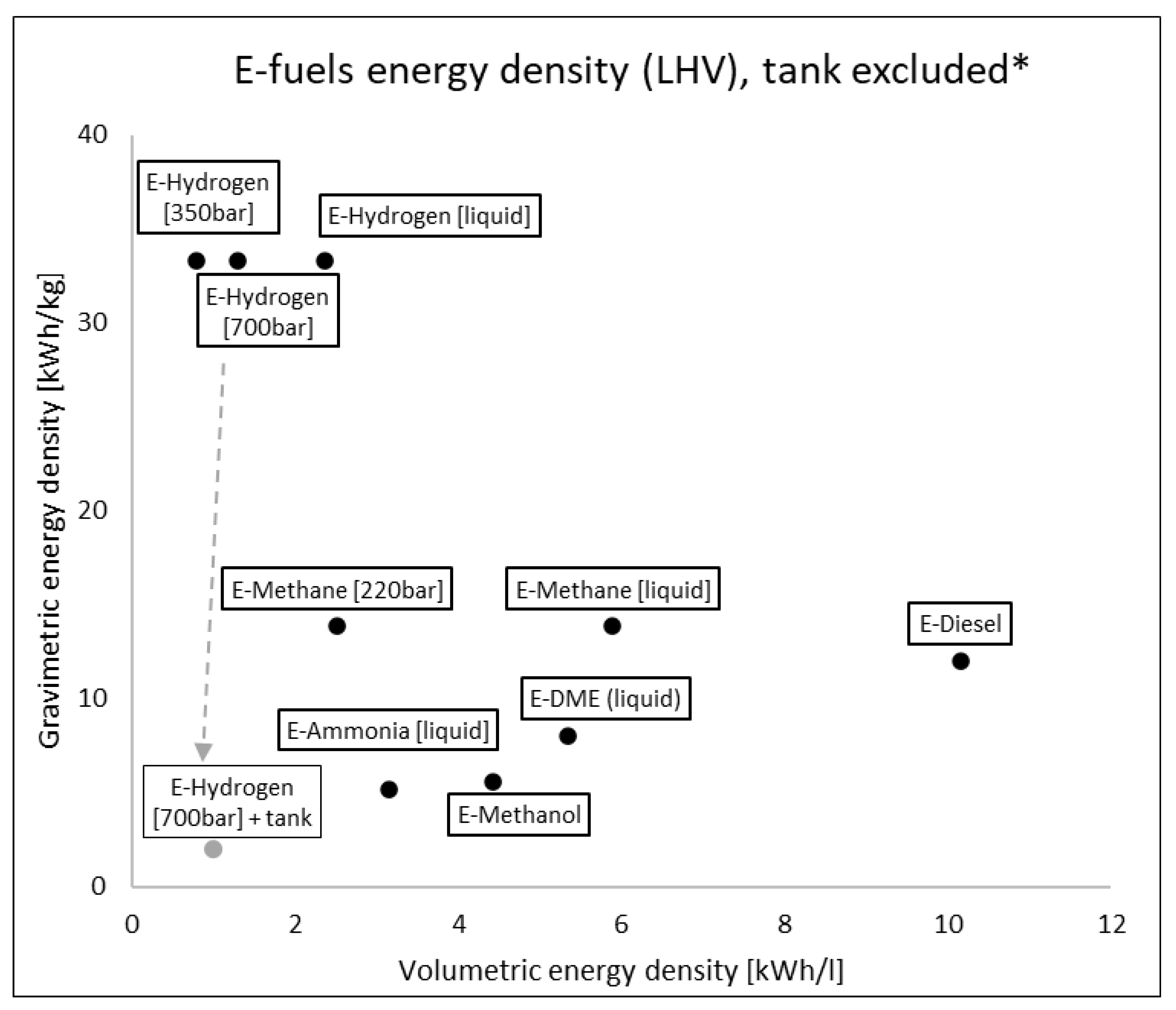
The e-fuels considered are reported in Table 1 with their relative mass and energy densities (both gravimetric and volumetric) at 15 °C, 1 atm. The volumetric energy density is a much more relevant limitation for road transport, even more than gravimetric, especially for PCs. There are huge differences between liquid e-fuels and gaseous ones, with up to 3–4 orders of magnitude.
Table 1. E-fuel main properties. Data from
[2][3][4].
| |
Chemical Formula |
LHV [MJ/kg] |
LHV [kWh/kg] |
Density @15 °C, 1 atm [kg/m3] |
LHV @15 °C, 1 atm [kWh/L] |
Explosivity Range |
Autoignition Temperature [°C] |
| E-Hydrogen |
H2 |
120.0 |
33.3 |
0.084 |
0.0028 |
4–75% |
560 |
| E-Methanol |
CH₃OH |
20.1 |
5.6 |
791 |
4.4164 |
6–36.5% |
420 |
| E-Diesel |
CnH2n+2 |
43.2 |
12.0 |
846 |
10.1520 |
1–6% |
225 |
| E-Ammonia |
NH3 |
18.6 |
5.2 |
0.72 |
0.0037 |
16–25% |
630 |
| E-DME |
CH3OCH3 |
28.9 |
8.0 |
1.96 |
5.3385 |
2–50% |
350 |
| E-Methane |
CH4 |
49.9 |
13.8 |
0.671 |
0.0093 |
5–15% |
635 |
If the comparison is carried out with e-fuels at different conditions, selecting the most viable onboard storage solutions (compressed and liquid E-Hydrogen, compressed and liquid E-Methane, liquid E-Ammonia, liquid E-DME), differences are reduced but still relevant (up to x10,
Figure 2). Considering also the containment system for e-fuels, densities are further reduced because cryogenic and high-pressure conditions require tanks with extreme insulation and high mechanical resistance
[5]. For example, a cylindric tank containing 4.1 kg of hydrogen at 700 bar has a mass of 66 kg
[6] with a huge impact on energy density: from 33.3 kWh/kg of H2 molecule to ca. 2 kWh/kg considering also the tank.
Figure 2. E-fuels gravimetric and volumetric energy density on LHV basis without containing system. * Example of tank influence only for e-hydrogen at 70 MPa.
Moreover, it is important to highlight the amount of energy consumed for compression and liquefaction of e-fuels which must be accounted in a fair ‘well-to-wheels’ analysis:
-
Hydrogen compression to 700bar requires 5.3–6 kWh/kg (16–18% of LHV), liquefaction 10–15 kWh/kg (30–45% of LHV)
[3][7][8].
-
Methane compression to 220 bar 0.15 kWh/kg (1% of LHV) and liquefaction 0.3–0.6 kWh/kg (2–4% of LHV)
[9].
Conversion of e-hydrogen into other e-fuels has a maximum theoretical conversion efficiency (on an LHV basis) determined by the chemical stoichiometry of the synthesis reaction:
where R is the coreactant (CO2 or N2), E is the e-fuel, and S is the potential side product. The values of a, b, c, and d depend on the stoichiometry of the reaction. An overall efficiency ηPtX, crucial for well-to-wheel analysis, could be defined as the ratio of e-fuel LHV to electrical PtX-specific consumption:
In Table 2 energetic performance of e-fuel pathways from synthesis to vehicle fuel tank are summarized.
Table 2. E-fuel pathways from synthesis to vehicle tank. Based on
[2][9][10][11].
| |
Theoretical Conversion Efficiency from Hydrogen |
Typical Plant Conversion Efficiency from Hydrogen |
Thermophysical Conversion for Storage [kWh/kg] |
Typical Overall PtX Efficiency |
E-Fuel Transportation to Final User [kWh/kWhfuel] |
WTT Efficiency |
| E-Hydrogen (700 bar) |
- |
- |
5.5 |
0.60 |
0.09 |
0.55 |
| E-Hydrogen (liquid) |
- |
- |
11 |
0.54 |
0.1 |
0.49 |
| E-Methanol |
0.886 |
0.797 |
- |
0.53 |
0.07 |
0.49 |
| E-Diesel |
0.834 |
0.693 |
- |
0.46 |
0.05 |
0.44 |
| E-Ammonia |
0.870 |
0.783 |
- |
0.52 |
0.07 |
0.48 |
| E-DME |
0.915 |
0.824 |
- |
0.55 |
0.07 |
0.51 |
| E-Methane (220 bar) |
0.825 |
0.743 |
0.15 |
0.50 |
0.07 |
0.47 |
| E-Methane (liquid) |
0.825 |
0.743 |
0.5 |
0.49 |
0.07 |
0.46 |
2. E-Hydrogen
E-hydrogen is produced through water electrolysis, an electrochemical process that uses electricity to decompose water into oxygen and hydrogen:
The electrolysers currently available on the market are alkaline electrolysers (AEL); proton exchange membrane electrolysers (PEMEL) are in the development stage, and solid oxide electrolysers (SOEL) are still in the research/demonstration stage
[12].
AEL rely on mature and technically well-known technology, and the most used electrolytes are aqueous solutions of potassium hydroxide (KOH) or sodium hydroxide (NaOH). These electrolysers can produce very pure hydrogen and have a relatively low investment cost; however, alkaline electrolytes can be corrosive and cannot start quickly. Instead, in the anode of PEMEL, the water molecule is split into the oxygen, electrons, and protons (H
+) passing through the electrolytic membrane, which reach the cathode where they are reduced to form hydrogen molecule H
2. PEMEL could also operate with variable load profiles, typical of nonpredictable renewable energy sources (RES), but they need noble metals for electrodes, increasing the capital cost. In SOEL, a flow of water vapour arrives at the cathode where the water is reduced, producing hydrogen molecules and O
2-anions which move to the anode where they form an oxygen molecule. SOEL operates at high temperatures, resulting in lower electricity requirements due to thermal activation, but they must be integrated with other heat sources
[13].
Table 3 reports the main characteristics of AEL, PEMEL, and SOEL.
Table 3. Main characteristics of electrolyser types. Based on
[14][15][16].
| |
AEL |
PEMEL |
SOEL |
| Temperature range [°C] |
60–90 |
50–90 |
500–1000 |
| Pressure range [barA] |
2–30 |
15–30 |
<30 |
| Energy consumption [kWh/kgH2] |
50–73 |
50–73 |
>42 |
| Lifetime of stack [h] |
<90,000 |
<20,000 |
<40,000 |
| Lifetime of system [year] |
20–30 |
10–20 |
- |
| Capital cost [€/kW] |
800–1500 |
900–2200 |
<2000 |
| Technology readiness level [TRL] |
9 |
5–7 |
3–5 |
So-called ‘Green Hydrogen’ refers to hydrogen produced by electrolysis using excess electricity generated by renewable sources that cannot be dispatched. ‘Yellow Hydrogen’, on the other hand, is produced through electrolysis without relying exclusively on surplus electricity and thus has a CO2 equivalent emission [1] that must be considered in an accurate well-to-wheels evaluation for its end use, such as for road transport vehicles.
3. E-Methanol
Methanol is currently derived almost entirely from fossil fuels (natural gas for about 85% and coal for about 15%)
[17], and it is used for the production of formaldehyde from which plastics and other coating products are obtained. It can be synthesised directly from H
2 and CO
2, usually with copper and zinc-based catalysts, in a reactor usually operating at 230–250 °C and 80 bar. To produce 1 kg of methanol, 1.37 kg of CO
2 and 0.19 kg of H
2 are required.
One of the first large-scale conversions of CO
2 to methanol dates back to the first 1990s by Lurgi AG, which developed a two-stage process
[18], and since then, dozens of plants were designed and built
[19]. In the case of e-methanol, obviously, hydrogen is produced with water electrolysis, and CO
2 is captured directly from the air or from flue gas that eventually would be released in the ambient. In Iceland is operating a plant of e-methanol that use carbon dioxide recovered from geothermal power stations with an overall efficiency of 0.42
[20]. There are several technologies available for CO
2 capture reported in
Table 4: Industrial separation and postcombustion are widely used (TRL up to 9) followed by precombustion, oxy-fuel combustion (from TRL up to 7), and DAC (TRL 7)
[21].
Table 4. Energetic performance of CO
2 capture technologies. Based on
[2][21].
| CO2 Capture Technology |
CO2 Removal Efficiency [%Vol] |
Energy Consumption [kWh/kgCO2] |
| Industrial Separation |
90 |
1.38 |
| Postcombustion |
90 |
1.15 |
| Precombustion |
90 |
0.93 |
| Oxy-Fuel Combustion |
>90 |
1.13 |
| Direct Air Capture (DAC) |
85–93 |
1.45 |
Electricity consumption, only for the reactants needed to synthesise 1 kg of e-methanol, is about 10 kWh for H2 and up to 2 kWh for CO2 (considering DAC) with a proportion of 5:1. Electrolysis is the most energy-consuming step of the whole process, but carbon dioxide also has a non-negligible impact.
Methanol can be easily used in SI-ICE due to its characteristics: high RON, high heat of vaporisation, high energy per unit of fuel–air mixture, high flame speed, low combustion temperature, and a high hydrogen-to-carbon ratio. Methanol can be burned as a single fuel or blended with gasoline. The modifications needed for spark-ignition ICEs are simple, and a significant amount of gasoline/alcohol flex-fuel ICE is currently running around the world
[22].
Regarding FCs, the direct use of methanol is possible (DMFCs), but the technology is only at the research stage
[23]. Methanol could be also reformed onboard to hydrogen and used in PEMFCs, but this concept seems limited to bigger applications, such as water transport and not road transport.
4. E-Diesel
Historically, the Fischer–Tropsch (FT) process was used to convert syngas (CO/H2) to liquid hydrocarbons as an alternative route with respect to traditional fossil–oil refineries. FT could not only be coupled to coal gasification and natural gas (NG) reforming but also biomass [24]; the reaction equation, where n is typically 10–20, is:
Direct utilisation of CO
2 and H
2 (from electrolysis) is possible with direct hydrogenation of CO
2 to alkanes
[25], but it is still at a very early stage of research
[19]. The existing real plants rely on the shift of CO
2 to CO to replicate the syngas composition of traditional coal/NG FT plants
[26]. A CO
2 shift could be obtained in a reverse water gas shift (RWGS) reactor or in coelectrolysis as demonstrated by the few projected/existing pilot plants
[27][28].
E-diesel production through FT-synthesis, starting from electrolytic H
2, has an efficiency factor of 0.82 to 0.83
[10], which is lower than other e-fuel routes due to the complex upgrading process. On the other hand, e-diesel is the most ‘transparent’ e-fuel regarding its logistics, refuelling network, and onboard use: E-diesel could be used in existing ICE vehicles and gas stations simply as a substitute or additive to current fossil diesel.
5. E-Ammonia
The production of ammonia (NH3) is carried out by the Haber–Bosch process in which hydrogen, usually produced by the reforming of natural gas, reacts with nitrogen at 400–450 °C and 150–200 bar with an iron catalyst.
The optimal H
2/N
2 ratio is 2; each step allows for a conversion of about 25–35%. The ammonia is separated from the gas stream before recycling to the reactor, usually by cooling to −25 °C, which causes ammonia liquefaction
[29]. To produce 1 kg of e-ammonia, 0.18 kg of H
2 and 0.82 kg of N
2 are needed. In the case of e-ammonia, obviously, hydrogen will be produced via water electrolysis with the abovementioned technologies (AEL, PEMEL, SOEL). The combination with SOEL has the potential to achieve a better coupling with the ammonia synthesis process with higher efficiencies (up to 0.7
[5]) due to heat integration. However, this technology readiness is very low
[30]. The nitrogen needed for the Haber–Bosch process is captured from ambient air with three possible technologies: cryogenic separation, pressure swing adsorption (PSA), and membrane permeation. For large-scale ammonia plants, cryogenic distillation is the more convenient option due to the lowest specific consumption which is equal to 0.11 kWh/kgN
2 [31][32].
Electricity consumption, only for the reactants needed to synthesize 1 kg of e-ammonia, is about 9 kWh for H
2 and 0.09 kWh for N
2 (considering cryogenic separation) with a proportion of 100:1. So, nitrogen separation consumption has a minimal impact on overall e-ammonia production, which reaches global efficiencies above 0.5 in existing large-scale plants
[29].
Regarding application in ICEs, ammonia has significantly higher ignition energy and lower flammability when compared with fossil fuels. However, many ICE applications were conceived and tested in the last century
[33], both spark and compression ignited
[34]. Ammonia could also be burned in ICEs with a combustion promoter such as hydrogen, which can be obtained directly by onboard reforming a small portion of ammonia itself
[35].
With onboard reforming and purification, hydrogen PEMFCs can also be used, but the cost and dimension of the whole system are unsuitable for road transport. Direct use of ammonia in FCs is possible, in particular, with alkaline electrolyte types and solid electrolyte types. High-temperature ceramic fuel cells are the most promising because the high operating temperature (>600 °C) could promote ammonia decomposition with the presence of catalysts
[36]. However, these technologies have volume and mass requirements that are not compatible with road transport.
6. E-DME
Historically DME was a by-product of high-pressure methanol synthesis, but nowadays, it is produced exclusively by methanol dehydration in a so-called ‘two-stage synthesis’. However, DME can also be synthesised directly from syngas, such as e-diesel in FT processes, with two viable reaction routes:
Both reactions are used in commercial plants
[19]. For E-DME, besides electrolytic hydrogen, the carbon source is CO
2, which can be easily converted into CO with an RWGS. Direct hydrogenation of CO
2 to DME has been investigated
[37], but it is still at a low level of technological readiness
[38].
DME has a high cetane number, low ignition temperature, and high speed of vaporisation when injected into the cylinder. These characteristics make it a suitable fuel for CI-ICEs, with almost smoke-free combustion
[39], while the low RON makes application in SI-ICEs difficult. High exhaust gas recirculation (EGR) rates can be used to reduce NOx without penalties for PM and HC emissions. On the other hand, DME CI-ICEs emit more CO than diesel.
[40].
Only a few studies of direct DME-FCs can be found in the literature
[41][42], while the use of PEMFC with an onboard reformer has gained attention in recent years
[43]. However, both solutions seem inapplicable to road transport because of high temperature and volume/mass requirements.
7. E-Methane
Methane is the main component of fossil natural gas, and this is the main source of methane besides non-negligible biologic production, mainly from the anaerobic digestion of biomasses. However, methane could be synthesized with the hydrogenation of CO2:
E-methane, often called also synthetic natural gas (SNG), is produced with this reaction, also called the ‘Sabatier reaction’ in honour of the French chemist Paul Sabatier who discovered it. Usually, the CO
2 is compressed up to 30 bar and introduced into a methanation reactor at 300 °C
[9]. These are the optimal operating conditions for the Sabatier reaction to occur
[44].
Methane use in ICEs is a well-known application with fossil natural gas, especially in SI. Many PCs from different manufacturers are currently available on the market and equipped with tanks for compressed NG. The cryogenic liquid form (LNG) is also an attractive energy vector for heavy-duty trucks with much lower emissions than diesel and biomethane and bio-LNG cases proving the feasibility of decentralised production
[45].
 +1 credit