Your browser does not fully support modern features. Please upgrade for a smoother experience.
Submitted Successfully!
 +1 credit
Thank you for your contribution! You can also upload a video entry or images related to this topic.
For video creation, please contact our Academic Video Service.
| Version | Summary | Created by | Modification | Content Size | Created at | Operation |
|---|---|---|---|---|---|---|
| 1 | Khaled Laadjal | -- | 2047 | 2023-03-16 16:44:41 | | | |
| 2 | Conner Chen | + 6 word(s) | 2053 | 2023-03-20 02:43:26 | | |
Video Upload Options
We provide professional Academic Video Service to translate complex research into visually appealing presentations. Would you like to try it?
Cite
If you have any further questions, please contact Encyclopedia Editorial Office.
Laadjal, K.; Cardoso, A.J.M. Multilayer Ceramic Capacitors and Its Fabrication Process. Encyclopedia. Available online: https://encyclopedia.pub/entry/42276 (accessed on 16 July 2026).
Laadjal K, Cardoso AJM. Multilayer Ceramic Capacitors and Its Fabrication Process. Encyclopedia. Available at: https://encyclopedia.pub/entry/42276. Accessed July 16, 2026.
Laadjal, Khaled, Antonio J. Marques Cardoso. "Multilayer Ceramic Capacitors and Its Fabrication Process" Encyclopedia, https://encyclopedia.pub/entry/42276 (accessed July 16, 2026).
Laadjal, K., & Cardoso, A.J.M. (2023, March 16). Multilayer Ceramic Capacitors and Its Fabrication Process. In Encyclopedia. https://encyclopedia.pub/entry/42276
Laadjal, Khaled and Antonio J. Marques Cardoso. "Multilayer Ceramic Capacitors and Its Fabrication Process." Encyclopedia. Web. 16 March, 2023.
Copy Citation
The high performance, multi-functionality, and high integration of electronic devices are made possible in large part by the multilayer ceramic capacitors (MLCCs). Due to their low cost, compact size, wide capacitance range, low equivalent series inductance (ESL) and equivalent series resistance (ESR), and excellent frequency response, MLCCs play a significant role in contemporary electronic devices.
multilayer ceramic capacitors (MLCCs)
high-power density
failure mechanism
1. Introduction
Ceramic capacitors, film capacitors, and electrolytic capacitors are the three basic types of capacitors. The dielectric, structure, terminal connection technique, use, coating, and electrolyte may all be used to further classify each category (only for electrolyte capacitors) [1]. Since the number of stored charges is mostly dependent on the dielectric material, the dielectric categorization is the most used. Table 1 displays some of the above categories of dielectric properties [2][3].
| Capacitors Categories | Dielectric | Dielectric Constant (εr) | Dielectric Thickness (d) |
|---|---|---|---|
| Electrolyte | Aluminum Oxide | [8, 10] | [0.03, 0.7] μm |
| Tantalum Oxide | [23, 27] | [0.04, 0.5] μm | |
| Film | Polyester Film | ≅3.2 | [0.5, 2] μm |
| Ceramic | Barium Titanate | [0.5, 20] × 103 | [2, 3] μm |
| Titanium Oxide | [15, 250] | [2, 3] μm |
As it was previously possible to establish, the properties of the dielectric dictate how the capacitor behaves. This is generally the case for all capacitors, however for exceptionally high-power capacitors, the permeability of the plates, tabs, and connections may also be used to calculate the highest peak current of the capacitor.
Table 1 makes it abundantly evident that the various kinds of capacitors have varied properties, thus which capacitor to use relies on the properties of the circuit in which it will be used. The following are a few of the most crucial factors to take into account while making a decision [1]:
- ○
-
Ratted voltage, capacitances, price, volumetric efficiency, consistency and dependability of capacitances, longevity, and power density.
- ○
-
Current ripple ratting and maximum peak current.
- ○
-
Temperature range, insulating resistance, and leakage current.
- ○
-
Capacitor performance and resonance frequency (capacitance dependency with frequency and temperature, as well as its internal resistance).
The most common type of capacitor in electronics is a ceramic one, and the most popular type of these is called a multilayer ceramic capacitor (MLCC). Many electrical products, including computers and cell phones, use MLCCs. Three kinds of commercially available dielectrics can be distinguished: Categories I, II, and III [4].
Titanium oxide, which has the lowest dielectric constant of the ceramic technologies, is used as a dielectric in Class I dielectrics, which are also known as temperature compensated dielectrics (Table 1). These capacitors are useful for several electronic systems circuits, including snubber circuits and soft-start circuits, due to their poor volumetric efficiency and tiny capacitance values (100 nF). Along with being relatively stable with voltage, temperature, and time, the capacitance additionally has a low dissipation factor [5].
Class II dielectrics, also known as high dielectric constant materials, use the high dielectric constant material barium titanate as a dielectric (Table 1). These capacitors are produced due to their compact sizes and high capacitance values. Their dissipation factor is therefore relatively large, and their capacitance tends to be unstable in response to voltage, temperature, and time [2][3][4]. The maximum capacitance variation over a temperature range is determined by the final digit of the three-character alphanumeric code used to describe Class II dielectrics. For instance, because the maximum temperature change for the X5R, X7R, and X8R’s capacitance is 15%, these devices are recommended for use in power electronics circuits. Both classes have higher dielectric resistance and lower dissipation factors when compared to Al-caps, but they have worse properties when compared to MK capacitors. Class III dielectrics, which have the highest capacitance and maximum volumetric efficiency of the three classes, are used to construct barrier layer capacitors. However, temperature, voltage, and frequency have a significant impact on them. Additionally, they operate at a voltage of about 25 V. Class III ceramic capacitors are frequently used in bypass coupling when dielectric losses, strong insulation resistance, and stability are not required [4].
Class II and class III capacitors, which tend to have greater dielectric constants and smaller breakdown fields, are therefore better suited for low-voltage applications, particularly where considerable capacitance is needed. The failure of ceramic capacitors during dielectric breakdown, which renders the device worthless, is another pertinent component of these devices [6].
For power devices, Cer-aLinkTM, a new ceramic capacitor technology from EPCOS, may be the ideal option. Recent research has shown that this technology can be particularly useful in the DC-link of voltage source inverters because of its promising properties, including low losses, rising capacitance with applied voltage, low series inductance, and high-capacitance density [7][8].
The necessity for portable electronic devices that can be connected to high-speed, high-transmission-capacity networks has increased, as shown by words like “digital nomad”, “ubiquitous computing” and “internet of things.” These breakthroughs have accelerated research on electronic components with high performance, great reliability, and low power consumption. The multilayer ceramic capacitor (MLCC), which is one of them, is the most significant passive element capable of storing and releasing electrical charge. For resonant circuit applications, MLCCs provide excellent stability and low losses, as well as great volumetric efficiency for buffer, by-pass, and coupling applications [5][9][10][11].
Prior studies, including those conducted by the authors of [12] and [13][14][15][16][17][18][19], have evaluated an MLCC’s dependability under high-acceleration impacts, mostly focusing on structural failure for an MLCC’s electrical, mechanical, and thermal interaction [20]. Using a multiscale homogenization modeling method, the authors of article [21] created a finite element simulation model to describe the structural characteristics of multilayer ceramic capacitors. In [22], it was discovered that the electric field distortion brought on by the impact-driven deformation of an MLCC can quickly lead to ceramic capacitor failure. This was demonstrated using the analogous mechanical model. Through a dynamic experiment with a high-overload impact, an MLCC failed. The impact of this failure on an advanced system was then examined.
Energy-storage and conversion technologies are envisaged for use in practical applications because they have a wide operating temperature range, are inexpensive, have a high energy density, a high-power density, and a high conversion efficiency. Figure 1 illustrates the energy and power density requirements for typical energy-storage systems [23].
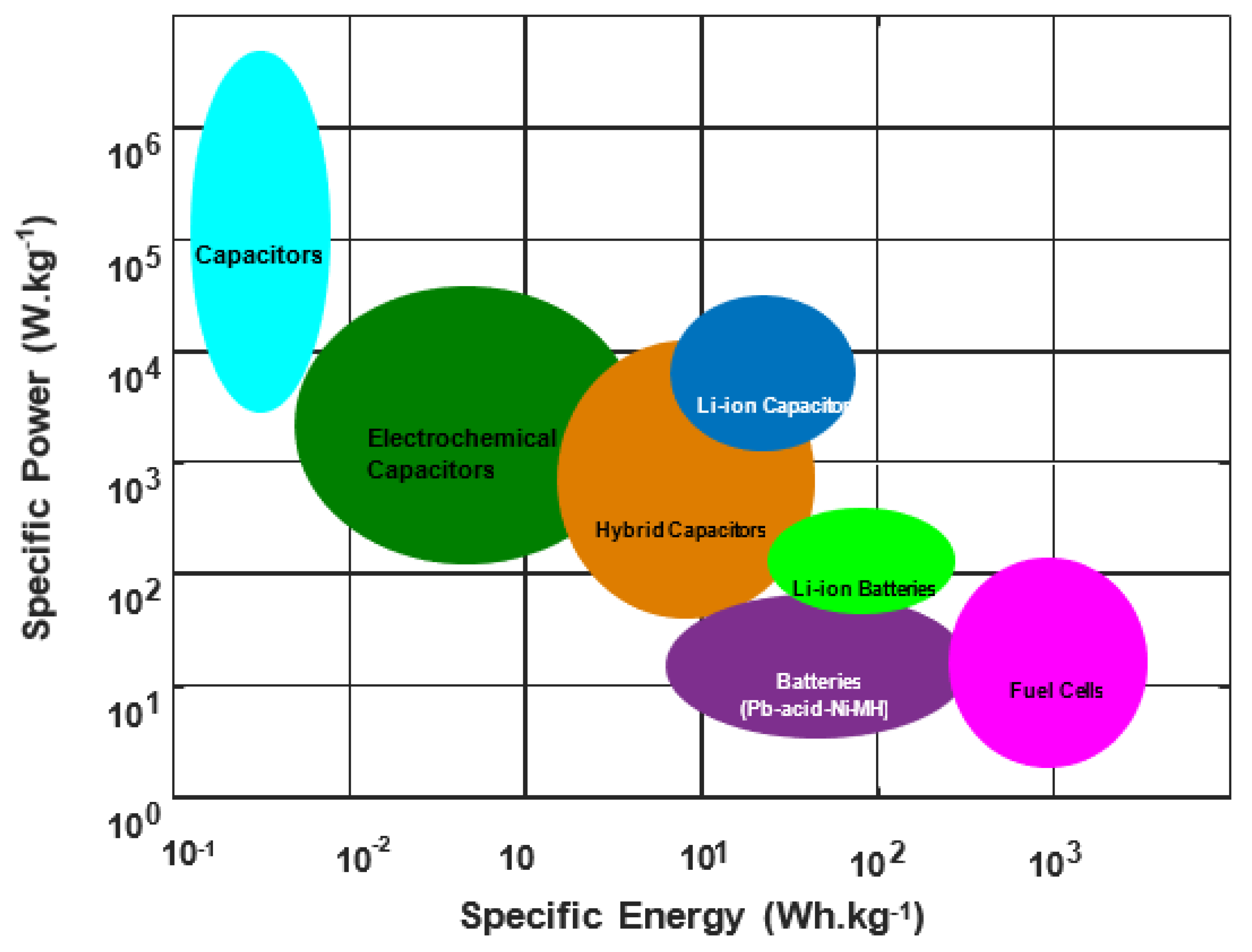
Figure 1. Energy density and power density relationships for popular energy-storage devices [23].
Dielectric capacitors offer ultra-high-power densities > 10 kW kg−1 in comparison to conventional energy-storage devices. As a result, they have ultra-high charging and discharging speeds and may start releasing accumulated energy in a nanosecond or microsecond time frame scale, allowing for exceptionally high pulse power. They also offer beneficial qualities, including an extremely long cycle life, dependability, and safety.
Dielectric capacitors are therefore essential for the development and application of third-generation semiconductor devices. These components are also utilized in high-power energy-storage and pulse power systems, which include electromagnetic weapons, advanced medical equipment, electric and hybrid vehicles, and smart grids [24][25]. However, the energy density of currently available commercial polymer dielectric capacitors is quite low (0.1 Wh.kg−1), leading to relatively large and heavy energy-storage and pulse-power devices.
For instance, the capacitors under each carriage of a high-speed train weigh more than 50 kg and occupy 50% of the space and 60% of the weight of the converter valves for high-voltage, direct-current transmission. This enormous volume would produce a significant equivalent series inductance (ESL) when switched quickly, which could harm or even cause the failure of semiconductor devices. This shows that these integrated capacitors cannot yet meet the specifications for use in electronic systems and devices that call for small, lightweight integrated capacitors [26][27].
2. MLCC and Its Fabrication Process
The exact structure and manufacturing procedure of the MLCCs are shown schematically in Figure 2. MLCCs are constructed by alternately layering numerous dielectric layers in tandem with inner electrodes. The inner electrodes are connected to the outside terminal for surface installation. In place of expensive Pd, base metals like Ni and Fe are increasingly used as inner electrode materials. The exterior termination is constructed of layers of Cu or Ag, Ni plating, and Sn plating. It is possible to express the MLCC capacitance as in Equation (1). When choosing the chip size and dielectric materials, the thickness of the dielectric layer and the number of stacked layers are important design considerations for MLCCs with high capacitance [28].
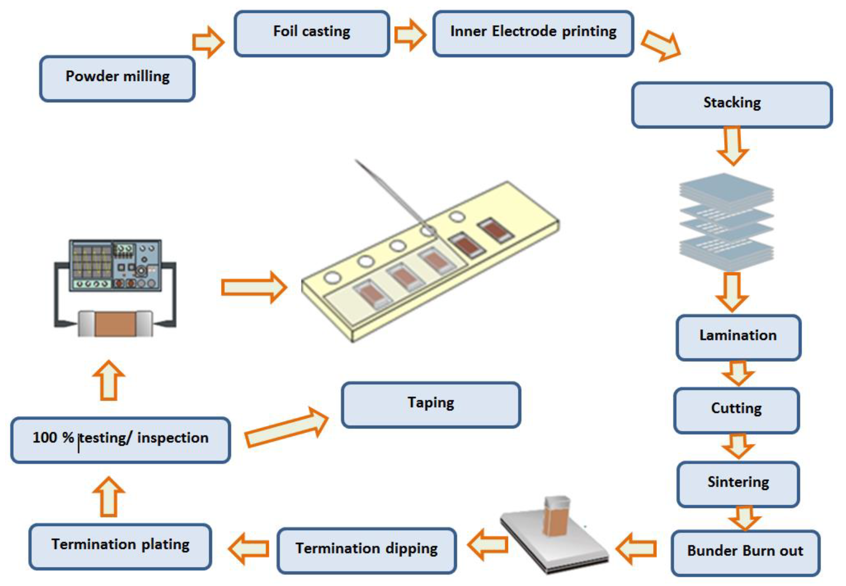
Figure 2. MLCC architecture and fabrication process schematics.
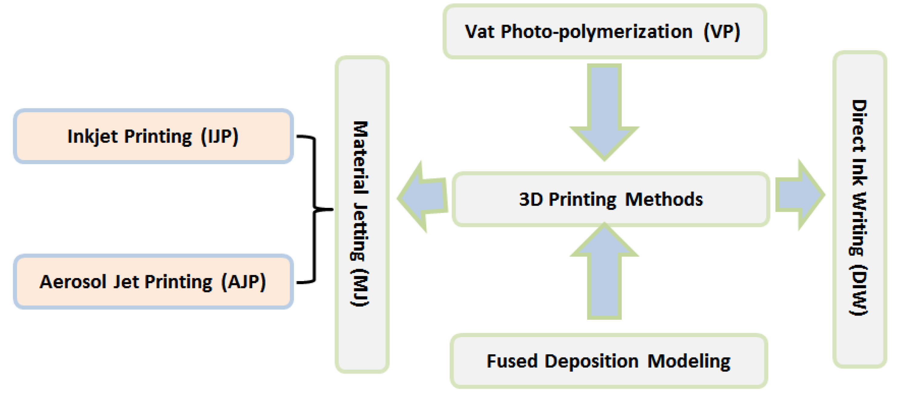
This process is commonly used to create MLCCs. Firstly, the balling procedure is used to homogeneously blend fine ceramic powders used for dielectric layers with a binder, solvents, and additives like dopants and sintering aids. To improve the dependability and performance of MLCCs, the composition of the starting materials is strictly controlled. The slurry-like shapes of the combinations make them easy to handle and process. Using the tape-casting method, the slurry is cast into a thin, continuous film. After drying and being cut into equal-sized sheets, the green sheets are then screen printed with metal paste. The required number of green sheets are stacked using inner electrodes, and the stack is subsequently compressed to produce a laminate by applying pressure [29]. The laminated sheets are cut into appropriate bits for chips. For stacking and cutting, extremely high mechanical and alignment precision is required. After cutting, the chips’ binder is burned away, and the chips are then sintered. Since the chips have a multi-layered structure of dielectric layers and inner electrodes, controlling the sintering temperature and the environment is essential to preventing shrinkage and failures during the sintering process. To connect the internal electrodes in parallel on the chip, termination is made using the tumbling, dipping, and firing operations. The manufacture of MLCC chips is finished after electrical testing to ensure quality. The manufacture of high-capacitance MLCCs is fraught with problems. Fine raw powders (o300 nm) are needed for thinner and smoother inner electrode layers and dielectric layers. As a result, there has been a lot of study into the manufacturing of tiny particles for the metal inner electrode and the dielectric layer [30]. Functional ceramic devices have reduced in size and become thinner, more refined, and more integrated in recent years, making it challenging to implement their fast prototyping and low-cost manufacture using conventional techniques. Multi-material 3D printing is an emerging technology that offers greater complexity and more creative freedom in the design of functional ceramic devices due to its singular capacity to instantly create 3D parts that incorporate various material constituents without the need for a time-consuming procedure or expensive tools [31][32][33][34]. However, strip lines, micro-strip lines, and vias are typically present in functional ceramic devices with composite structures that are made of two or more materials. In addition to improving the spatial resolution and printing speed, numerous issues relating to the raw materials, printing strategies, and sintering process still need to be resolved. Functional ceramic devices are now being developed via multi-material 3D printing, which has considerable research motivation and application promise [35][36]. Some popular 3D printing processes are shown in Figure 3.
Conventional MLCCs based on BaTiO3 have been fabricated with noble metals such as platinum (Pt) or palladium (Pd) as internal electrodes which can be fired with dielectrics in air at 1300 °C or higher. With an increased number of stacked layers due to miniaturization and higher capacitance of MLCCs, the proportion of the electrode cost to the overall cost increases steeply. Thus, a cost reduction of the internal electrodes has been intensively investigated for reducing the cost of MLCCs [37]. Methods for reducing the internal electrode cost are classified into:
- (1)
-
The use of silver (Ag)/Pd alloy electrodes having a high Ag content (more than 70%) to achieve low temperature sintering of the dielectrics.
- (2)
-
The use of base metals such as nickel (Ni) and copper (Cu) as internal electrodes by using a nonreducible dielectric that can be fired in a reducing atmosphere [38].
Table 2 shows the physical properties and price ratio of various electrode materials for MLCCs.
Table 2. Different electrodes’ physical characteristics and price ratio.
| Metals | Melting Point (°C) | Resistivity (mΩ) | Price Ratio |
|---|---|---|---|
| Ag | 961 | 1.62 | 3 |
| Cu | 1080 | 1.72 | 1 |
| Ni | 1453 | 6.9 | 1 |
| Pd | 1552 | 10.4 | 80 |
The performance, dependability, and functionality of the electrode materials used in MLCCs are negatively impacted by residual stress, mechanical cracking from sintering shrinkage, and metal diffusion into the dielectric layer, all of which are caused by high sintering temperatures for dielectric materials. In order to avoid the oxidation of the base metal inner electrode, the green chips are additionally co-fired at low oxygen pressure. During sintering in a reducing environment, dielectric layers can experience a significant compositional change and defect development. The sintering environment must be meticulously regulated to minimize decrease of the dielectric material and to limit oxidation of the inner electrodes [39][40].
References
- Cardoso, A.J.M. Diagnosis and Fault Tolerance of Electrical Machines and Power Electronics; 2018; p. 376. ISBN 13: 978-1-78561-531-1. Available online: https://www.researchgate.net/publication/328676133_Diagnosis_and_Fault_Tolerance_of_Electrical_Machines_Power_Electronics_and_Drives (accessed on 1 February 2023).
- Yuan, Q.; Chen, M.; Zhan, S.; Li, Y.; Lin, Y.; Yang, H. Ceramic-Based Dielectrics for Electrostatic Energy Storage Applications: Fundamental Aspects, Recent Progress, and Remaining Challenges. Chem. Eng. J. 2022, 446, 136315.
- Covaci, C.; Gontean, A. “Singing” Multilayer Ceramic Capacitors and Mitigation Methods—A Review. Sensors 2022, 22, 3869.
- Pan, M.-J.; Randall, C.A. A brief introduction to ceramic capacitors. IEEE Electr. Insul. Mag. 2010, 26, 44–50.
- Pithan, C.; Hennings, D.; Waser, R. Progress in the synthesis of nanocrystalline BaTiO3 powders for MLCC. Int. J. Appl. Ceram. Technol. 2005, 2, 1–14.
- Ho, J.; Jow, T.R.; Boggs, S. Historical introduction to capacitor technology. IEEE Electr. Insul. Mag. 2010, 26, 20–25.
- Kropp, J.; Bakran, M.-M. In-circuit-characterization of ceramic capacitor with anti-ferroelectric material for voltage source inverters. In Proceedings of the PCIM Europe 2016, International Exhibition and Conference for Power Electronics, Intelligent Motion, Renewable Energy and Energy Management, Nuremberg, Germany, 10–12 May 2016; pp. 1–8.
- Neumayr, D.; Bortis, D.; Kolar, J.W.; Koini, M.; Konrad, J. Comprehensive large-signal performance analysis of ceramic capacitors for power pulsation buffers. In Proceedings of the 2016 IEEE 17th Workshop on Control and Modeling for Power Electronics (COMPEL), Trondheim, Norway, 27–30 June 2016; pp. 1–8.
- Hao, H.; Liu, M.; Liu, H.; Zhang, S.; Shu, X.; Wang, T.; Yao, Z.; Cao, M. Design, fabrication and dielectric properties in core–double shell BaTiO3-based ceramics for MLCC application. RSC Adv. 2015, 5, 8868–8876.
- Zhang, Y.; Wang, X.; Kim, J.; Tian, Z.; Fang, J.; Hur, K.H.; Li, L. High performance BaTiO3-based BME-MLCC nanopowder prepared by aqueous chemical coating method. J. Am. Ceram. Soc. 2012, 95, 1628–1633.
- Kishi, H.; Mizuno, Y.; Chazono, H. Base-metal electrode-multilayer ceramic capacitors: Past, present and future perspectives. Jpn. J. Appl. Phys. 2003, 42, 1.
- Dai, K.; Wang, X.; Niu, S.; Yi, F.; Yin, Y.; Chen, L.; Zhang, Y.; You, Z. Simulation and structure optimization of triboelectric nanogenerators considering the effects of parasitic capacitance. Nano Res. 2017, 10, 157–171.
- Archangelo, K.C.; Guilardi, L.F.; Campanelli, D.; Valandro, L.F.; Borges, A.L.S. Fatigue failure load and finite element analysis of multilayer ceramic restorations. Dent. Mater. 2019, 35, 64–73.
- Nagayoshi, M.; Matsubara, K.; Fujikawa, N. Analyses of microstructure at degraded local area in Ni-multilayer ceramic capacitors under highly accelerated life test. Jpn. J. Appl. Phys. 2020, 59, SPPC01.
- Kalaiselvan, C.; Rao, L.B. Accelerated life testing of nano ceramic capacitors and capacitor test boards using non-parametric method. Measurement 2016, 88, 58–65.
- Lall, P.; Dornala, K.; Suhling, J.; Deep, J.; Lowe, R. Effect of Dielectric Material on the Reliability of 3640 MLCC Capacitors under High-G Shock Loads. In Proceedings of the 2019 18th IEEE Intersociety Conference on Thermal and Thermomechanical Phenomena in Electronic Systems (ITherm), Las Vegas, NV, USA, 28–31 May 2019; pp. 1037–1046.
- Lall, P.; Dornala, K.; Deep, J.; Lowe, R. Measurement and Prediction of Interface Crack Growth at the PCB-Epoxy Interfaces Under High-G Mechanical Shock. In Proceedings of the 2018 17th IEEE Intersociety Conference on Thermal and Thermomechanical Phenomena in Electronic Systems (ITherm), San Diego, CA, USA, 29 May–1 June 2018; pp. 1097–1105.
- Lall, P.; Dornala, K.; Lowe, R.; Foley, J. Survivability assessment of electronics subjected to mechanical shocks up to 25,000 g. In Proceedings of the 2016 15th IEEE Intersociety Conference on Thermal and Thermomechanical Phenomena in Electronic Systems (ITherm), Las Vegas, NV, USA, 31 May–3 June 2016; pp. 507–518.
- Lall, P.; Patel, K.; Lowe, R.; Strickland, M.; Blanche, J.; Geist, D.; Montgomery, R. Modeling and reliability characterization of area-array electronics subjected to high-g mechanical shock up to 50,000 g. In Proceedings of the 2012 IEEE 62nd Electronic Components and Technology Conference, San Diego, CA, USA, 29 May–1 June 2012; pp. 1194–1204.
- Prume, K.; Waser, R.; Franken, K.; Maier, H.R. Finite-Element Analysis of Ceramic Multilayer Capacitors: Modeling and Electrical Impedance Spectroscopy for a Nondestructive Failure Test. J. Am. Ceram. Soc. 2000, 83, 1153–1159.
- Lee, S.P.; Kang, K.W. Analysis for deformation behavior of multilayer ceramic capacitor based on multiscale homogenization approach. J. Mech. Sci. Technol. 2018, 32, 2577–2585.
- Xuhui, Z.; Kuahai, Y.; Hongyu, X.; Bin, L.; Xingguo, K. Failure analysis of multilayer ceramic capacitor structure under high G impact load. Electron. Compon. Mater. 2016, 35, 28–31.
- Collins, J.; Gourdin, G.; Foster, M.; Qu, D. Carbon surface functionalities and SEI formation during Li intercalation. Carbon N. Y. 2015, 92, 193–244.
- Yao, Z.; Song, Z.; Hao, H.; Yu, Z.; Cao, M.; Zhang, S.; Lanagan, M.T.; Liu, H. Homogeneous/inhomogeneous-structured dielectrics and their energy-storage performances. Adv. Mater. 2017, 29, 1601727.
- Li, F.; Zhai, J.; Shen, B.; Zeng, H. Recent progress of ecofriendly perovskite-type dielectric ceramics for energy storage applications. J. Adv. Dielectr. 2018, 8, 1830005.
- Hao, X. A review on the dielectric materials for high energy-storage application. J. Adv. Dielectr. 2013, 3, 1330001.
- Zou, K.; Dan, Y.; Xu, H.; Zhang, Q.; Lu, Y.; Huang, H.; He, Y. Recent advances in lead-free dielectric materials for energy storage. Mater. Res. Bull. 2019, 113, 190–201.
- Li, J.; Li, F.; Xu, Z.; Zhang, S. Multilayer lead-free ceramic capacitors with ultrahigh energy density and efficiency. Adv. Mater. 2018, 30, 1802155.
- Wang, G.; Lu, Z.; Li, J.; Ji, H.; Yang, H.; Li, L.; Sun, S.; Feteira, A.; Yang, H.; Zuo, R.; et al. Lead-free (Ba, Sr) TiO3–BiFeO3 based multilayer ceramic capacitors with high energy density. J. Eur. Ceram. Soc. 2020, 40, 1779–1783.
- Zhao, P.; Wang, H.; Wu, L.; Chen, L.; Cai, Z.; Li, L.; Wang, X. High-performance relaxor ferroelectric materials for energy storage applications. Adv. Energy Mater. 2019, 9, 1803048.
- Chen, H.; Guo, L.; Zhu, W.; Li, C. Recent Advances in Multi-Material 3D Printing of Functional Ceramic Devices. Polymers 2022, 14, 4635.
- Reinheimer, T.; Azmi, R.; Binder, J.R. Polymerizable ceramic ink system for thin inkjet-printed dielectric layers. ACS Appl. Mater. Interfaces 2019, 12, 2974–2982.
- Wolf, A.; Rosendahl, P.L.; Knaack, U. Additive manufacturing of clay and ceramic building components. Autom. Constr. 2022, 133, 103956.
- He, Q.; Jiang, J.; Yang, X.; Zhang, L.; Zhou, Z.; Zhong, Y.; Shen, Z. Additive manufacturing of dense zirconia ceramics by fused deposition modeling via screw extrusion. J. Eur. Ceram. Soc. 2021, 41, 1033–1040.
- Wang, F.; Li, Z.; Lou, Y.; Zeng, F.; Hao, M.; Lei, W.; Wang, X.; Wang, X.; Fan, G.; Lu, W. Stereolithographic additive manufacturing of Luneburg lens using Al2O3-based low sintering temperature ceramics for 5G MIMO antenna. Addit. Manuf. 2021, 47, 102244.
- Liu, K.; Zhou, C.; Hu, J.; Zhang, S.; Zhang, Q.; Sun, C.; Shi, Y.; Sun, H.; Yin, C.; Zhang, Y.; et al. Fabrication of barium titanate ceramics via digital light processing 3D printing by using high refractive index monomer. J. Eur. Ceram. Soc. 2021, 41, 5909–5917.
- Gong, P.; Li, Y.; Xin, C.; Chen, Q.; Hao, L.; Sun, Q.; Li, Z. Multimaterial 3D-printing barium titanate/carbonyl iron composites with bilayer-gradient honeycomb structure for adjustable broadband microwave absorption. Ceram. Int. 2022, 48, 9873–9881.
- Xing, H.; Zou, B.; Liu, X.; Wang, X.; Huang, C.; Hu, Y. Fabrication strategy of complicated Al2O3-Si3N4 functionally graded materials by stereolithography 3D printing. J. Eur. Ceram. Soc. 2020, 40, 5797–5809.
- Zhang, T.F.; Tang, X.G.; Liu, Q.X.; Jiang, Y.P.; Huang, X.X.; Zhou, Q.F. Energy-storage properties and high-temperature dielectric relaxation behaviors of relaxor ferroelectric Pb (Mg1/3Nb2/3) O3–PbTiO3 ceramics. J. Phys. D Appl. Phys. 2016, 49, 095302.
- Wang, H.; Zhao, P.; Chen, L.; Wang, X. Effects of dielectric thickness on energy storage properties of 0.87 BaTiO3-0.13 Bi (Zn2/3 (Nb0.85Ta0.15) 1/3) O3 multilayer ceramic capacitors. J. Eur. Ceram. Soc. 2020, 40, 1902–1908.
More
Information
Subjects:
Materials Science, Ceramics
Contributors
MDPI registered users' name will be linked to their SciProfiles pages. To register with us, please refer to https://encyclopedia.pub/register
:
View Times:
5.6K
Revisions:
2 times
(View History)
Update Date:
20 Mar 2023
Table of Contents


Notice
You are not a member of the advisory board for this topic. If you want to update advisory board member profile, please contact office@encyclopedia.pub.
OK
Confirm
Only members of the Encyclopedia advisory board for this topic are allowed to note entries. Would you like to become an advisory board member of the Encyclopedia?
Yes
No
${ textCharacter }/${ maxCharacter }
Submit
Cancel
Back
Comments
${ item }
|
${ item.createdUser.fullName }
${ item.createdAt }
${ item.vote }
${ item.reply }
Delete
${ reply.createdUser.fullName }
${ reply.createdAt }
${ reply.vote }
Delete
There is no reply to this comment~
${ item.replyTextCharacter }/${ item.replyMaxCharacter }
Submit
Cancel
More
No more~
There is no comment~
${ textCharacter }/${ maxCharacter }
Submit
Cancel
${ selectedItem.replyTextCharacter }/${ selectedItem.replyMaxCharacter }
Submit
Cancel
Confirm
Are you sure to Delete?
Yes
No