Submitted Successfully!
To reward your contribution, here is a gift for you: A free trial for our video production service.
Thank you for your contribution! You can also upload a video entry or images related to this topic.
Version Summary Created by Modification Content Size Created at Operation
1 + 4713 word(s) 4713 2022-02-08 05:09:50 |
2 format correct -29 word(s) 4684 2022-02-15 01:46:40 | |
3 format correct -29 word(s) 4684 2022-02-15 01:55:27 | |
4 format correct Meta information modification 4684 2022-02-15 01:56:23 |

Video Upload Options

Do you have a full video?

Confirm

Are you sure to Delete?
Cite
If you have any further questions, please contact Encyclopedia Editorial Office.
Madejski, P.; Chmiel, K.; Subramanian, N.; Kuś, T. Methods and Techniques for CO2 Capture. Encyclopedia. Available online: https://encyclopedia.pub/entry/19427 (accessed on 20 April 2024).
Madejski P, Chmiel K, Subramanian N, Kuś T. Methods and Techniques for CO2 Capture. Encyclopedia. Available at: https://encyclopedia.pub/entry/19427. Accessed April 20, 2024.
Madejski, Pawel, Karolina Chmiel, Navaneethan Subramanian, Tomasz Kuś. "Methods and Techniques for CO2 Capture" Encyclopedia, https://encyclopedia.pub/entry/19427 (accessed April 20, 2024).
Madejski, P., Chmiel, K., Subramanian, N., & Kuś, T. (2022, February 14). Methods and Techniques for CO2 Capture. In Encyclopedia. https://encyclopedia.pub/entry/19427
Madejski, Pawel, et al. "Methods and Techniques for CO2 Capture." Encyclopedia. Web. 14 February, 2022.
Methods and Techniques for CO2 Capture
Edit

With the increase in electricity consumption around the world, electricity demands are increasing every day. During electricity generation using energy technologies based on fossil fuels, the emission of harmful pollutants into the environment (gaseous, liquid, and solid) occurs as the emission of NOx, SOx, dust, CO2, and wastewater (e.g., from flue-gas treatment installations). A great deal of effort in modern low-emission energy technologies was directed at activities leading to decreased gaseous pollutant emissions. The emission of carbon dioxide (CO2), treated as one of the main reasons for global warming when fossil fuel is burned, cannot be avoided. The carbon capture utilization and storage (CCUS) methods and technologies are among the many ways to reduce CO2 emissions.

CO2 capture methods Post-combustion CO2 capture Pre-combustion CO2 capture Oxy-combustion CO2 capture

1. Introduction

With the increase in electricity consumption around the world, electricity demands are increasing every day. During electricity generation using energy technologies based on fossil fuels, the emission of harmful pollutants into the environment (gaseous, liquid, and solid) occurs as the emission of NOx, SOx, dust, CO2, and wastewater (e.g., from flue-gas treatment installations) [1][2][3]. Last year, a great deal of effort in modern low-emission energy technologies was directed at activities leading to decreased gaseous pollutant emissions [4][5]. The emission of carbon dioxide (CO2), which is treated as one of the main reasons for global warming when fossil fuel is burned, cannot be avoided. Fossil-fueled power-production technology plays a significant role in contributing to the emission of greenhouse gases into the atmosphere. By reducing the emission of CO2 into the atmosphere, and by switching to an alternative power generation with zero-emission, it is possible to prevent future undesirable and dangerous consequences. The carbon capture utilization and storage (CCUS) methods and technologies are among the many ways to reduce CO2 emissions. CCUS technologies aim to capture CO2 from large industrial sources and store it in underground structures, or use it through conversion into useful products [6]. All this is happening while emissions from the industrial and energy sectors are reduced, which makes this process one of the most current scientific research endeavors, while also presenting socio-economic challenges. The current fees related to CO2 emissions in the European Union amount to over 50 EUR/tCO2 [7], and there is an expected upward trend for coming years, forced by political declarations and treaties.
There are four different ways to reduce CO2 emission levels [8]:
  • Reducing the use of fossil fuels by:
    ○ improving the efficiency of energy conversion processes;
    ○ reducing the demand for energy;
    ○ using renewable (non-fossil fuel) energy sources, such as hydropower, wind, biomass, solar cells, and nuclear power;
    ○ increasing the use of green hydrogen, which is produced by splitting water using electricity from renewable energy.
  • Replace technologies using fossil fuels with a low carbon to hydrogen C/H2 ratio by replacing coal and oil with gaseous fuels.
  • Capturing CO2 from fuel combustion in power plants and other industrial processes and storing it in appropriate geological structures, in exhausted or exploited gas or crude oil deposits (intensification of crude oil extraction, enhanced oil recovery (EOR)), or at the bottom of oceans.
  • Limiting deforestation processes and thus storing more CO2 in biomass.
Carbon capture utilization and storage (CCUS) is a family of methods to reduce the emission of CO2 from fossil-fueled power plants. The CCS can be coupled with Power Plants (PPs) and Combined Heat and Power Plants (CHPPs) to reduce the emission of CO2 in the flue gas. First-generation carbon capture technology had a lower efficiency in carbon capture, and was challenging to integrate with the complex structures of a power plant. With improved research and development, the second- and third-generation power plants using carbon capture technology showed improved efficiency and a low cost compared to first-generation CCS technology [9]. The three different methods (pre-, post-, and oxyfuel combustion) for CO2 capture and separation are under development. The oxyfuel combustion method is considered a promising solution from an energy-efficiency power-generation point of view. Authors have noted, that the energy penalty for the oxy-combustion method can be around 4%, in comparison to 8–12% for post-combustion methods [10].
The implementation of CCS in Europe is focused on two major factors, the development of power generation technology with carbon capture at a low cost and selling CO2 at a high price to reimburse the cost of CO2 transportation. In 2008, the European Parliament approved the “draft CCS directive”, which aims to guide CO2 geological storage. Due to public opposition from European Union countries for underground CO2 storage, many countries allow only offshore storage projects [11]. CCUS technologies are considered as crucial technologies for the European Commission, and are explicitly included in, e.g., the European Green Deal. Nowadays, more and more important projects at the industrial scale are funded by the Innovation Fund (https://ec.europa.eu/clima/eu-action/funding-climate-action/innovation-fund/large-scale-projects_en, accessed on 20 January 2022). The International Energy Agency forecasts that CCS will contribute up to 21% of the reduction in CO2 emissions into the atmosphere. Many countries, including Asian countries, still depend on coal-fired power production because of the low cost and reliability, and these cannot be wholly replaced with renewable energy systems. Some European countries, such as Poland, will depend on fossil-fuel power production for at least 30 more years. According to Polish Energy Policy, by the year 2050, electricity demand in Poland will be produced by renewable energy and future nuclear power projects. The use of coal for the next few years makes CCS technology inevitable [12]. Carbon capture and storage is a method for capturing the concentrated CO2 in flue gas from fossil-fueled power plants and store them in one place. There are three methods of CO2 capture: pre-combustion carbon capture, post-combustion carbon capture, and the oxy-combustion carbon capture method.
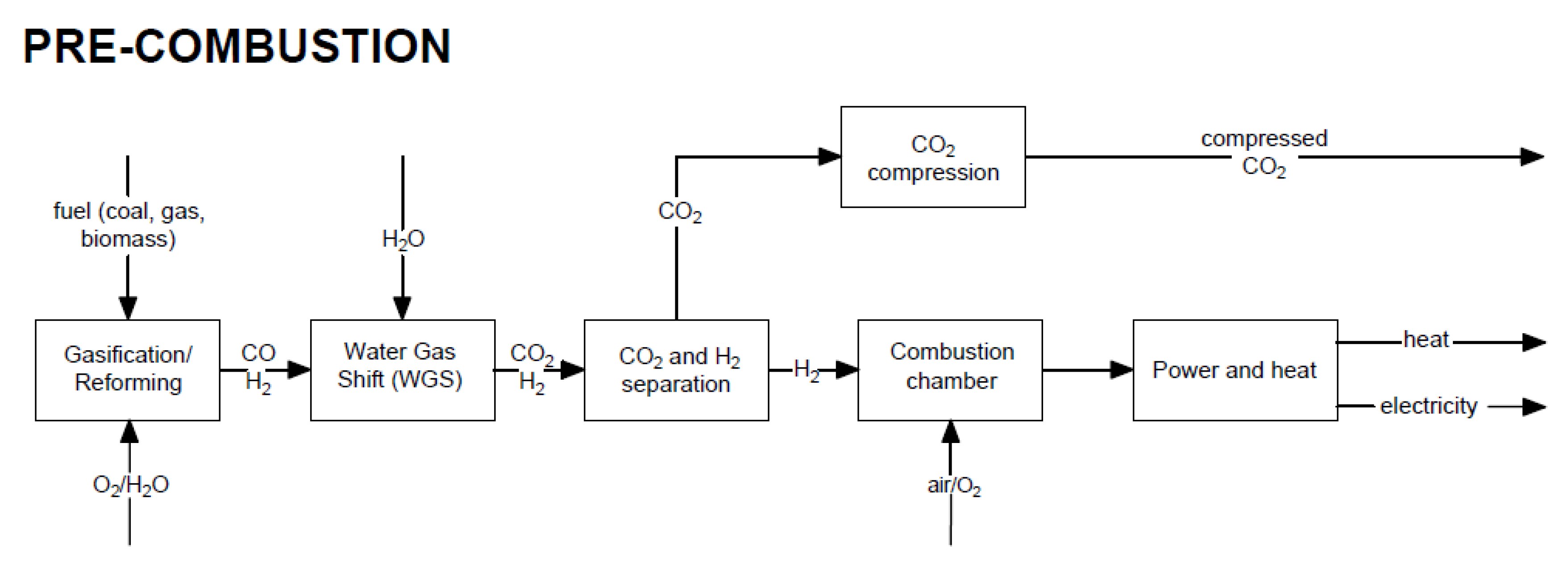
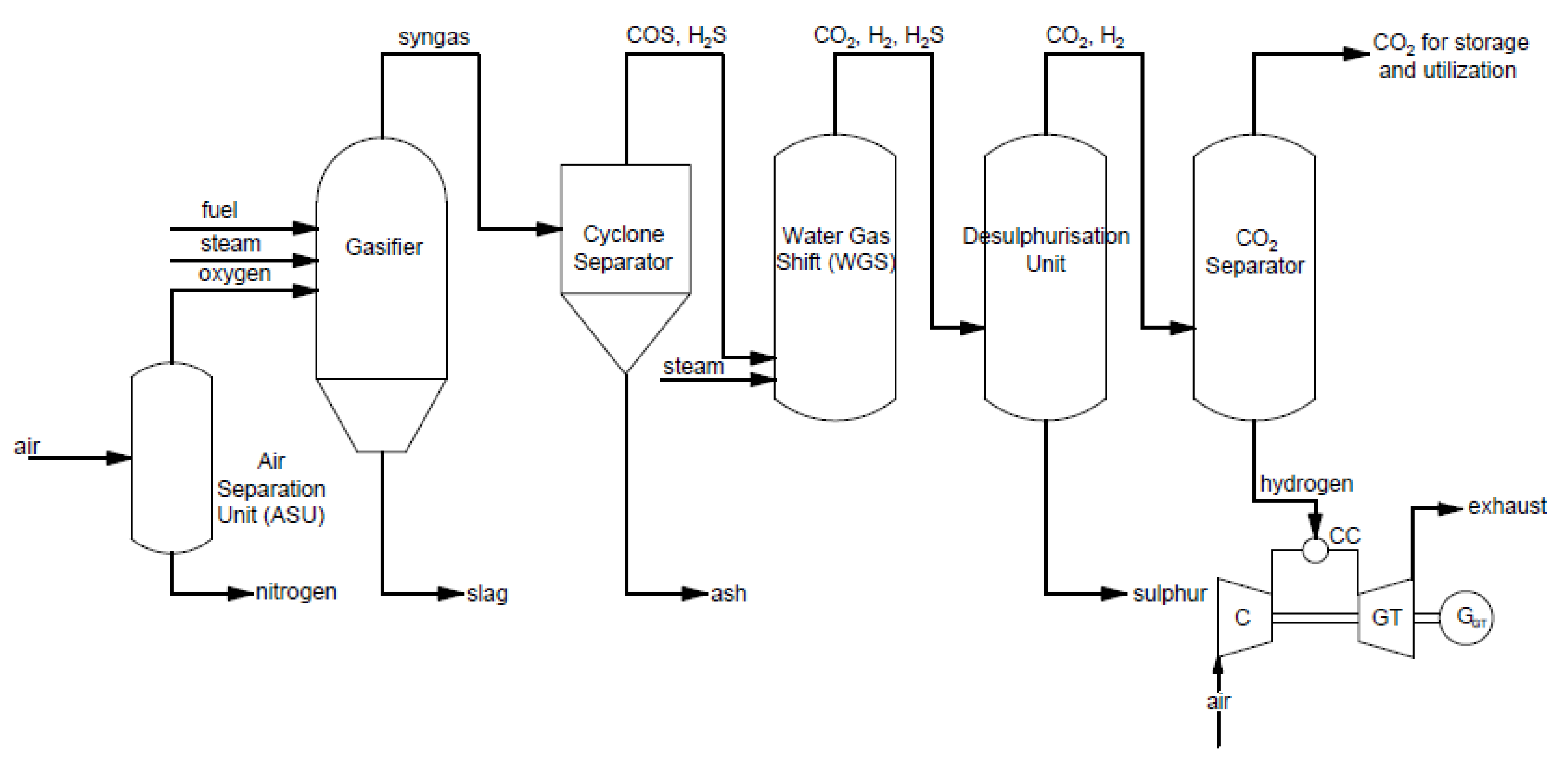
  • Pre-combustion carbon capture occurs before the combustion process (through fuel gasification with oxygen, e.g., integrated IGCC coal gasification technology).
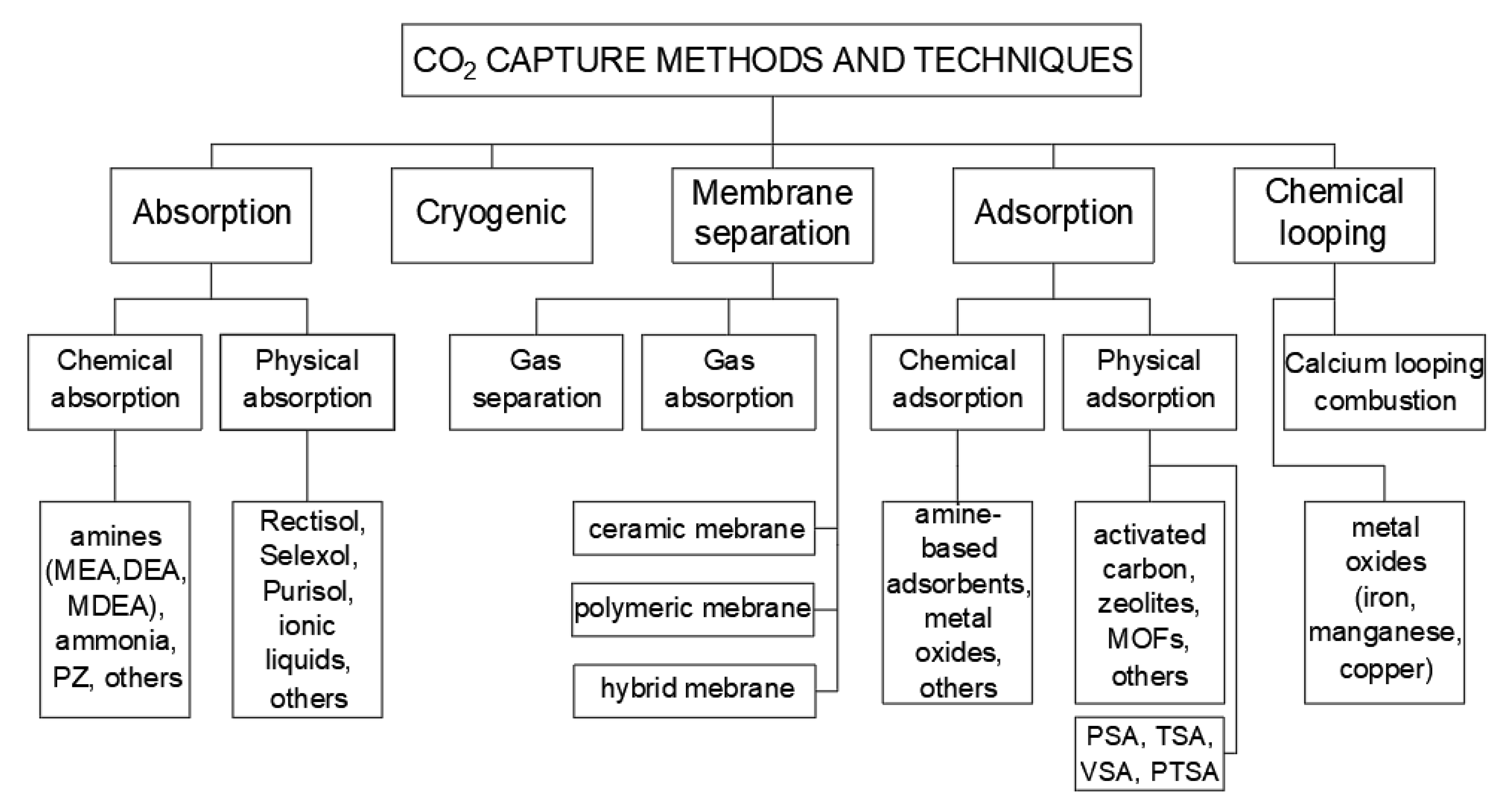
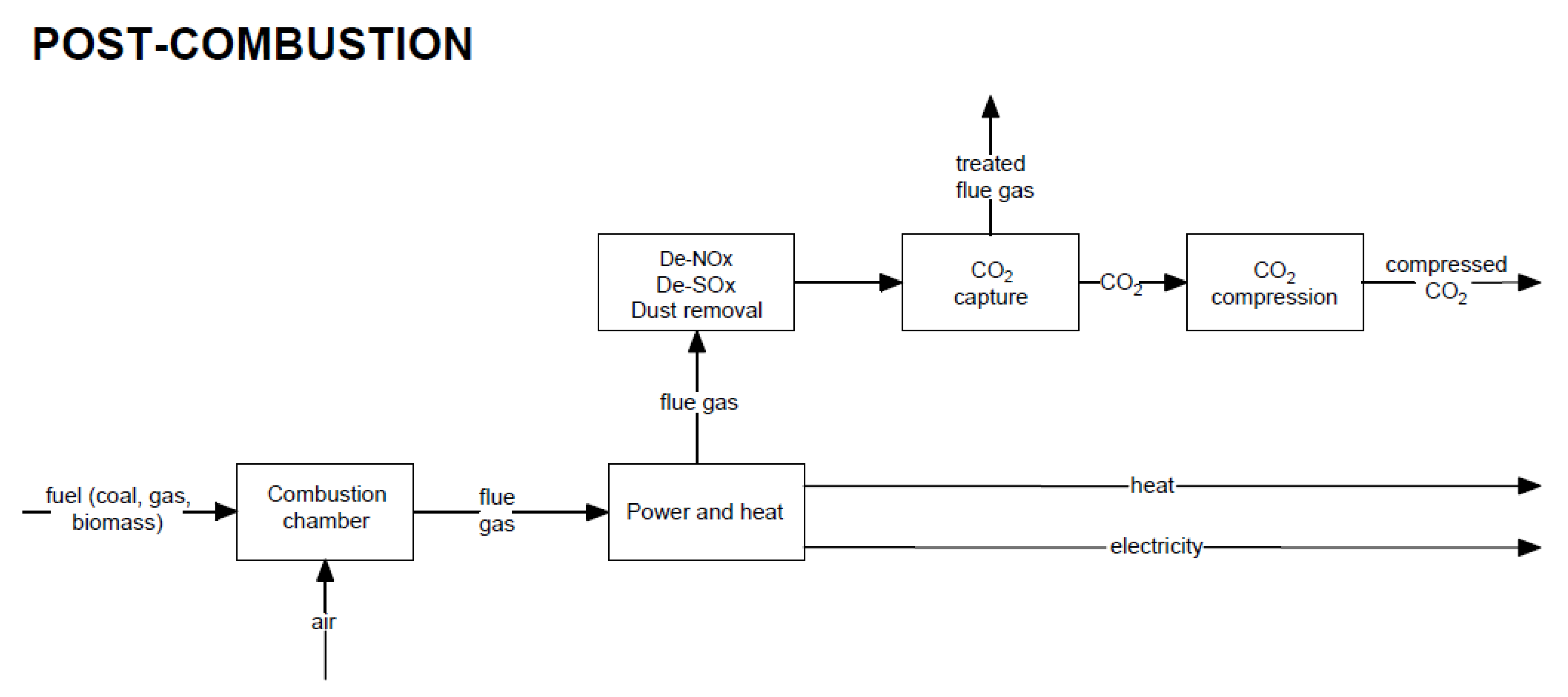
  • Post-combustion carbon capture occurs after the combustion process (capturing CO2 from flue gas, e.g., using chemical absorption, physical adsorption, membrane separation, or the use of a chemical loop).
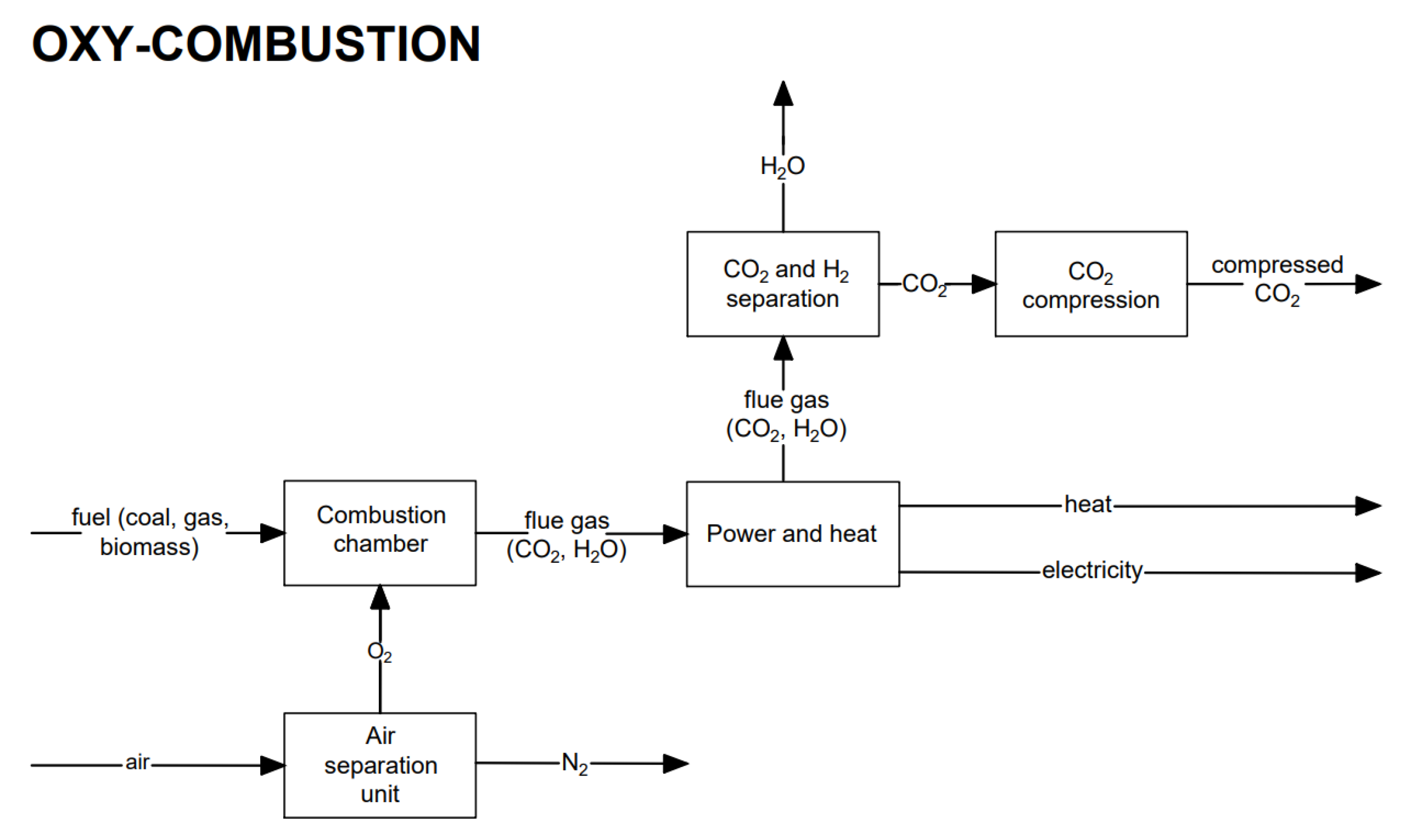
  • Oxy-combustion carbon capture occurs after the combustion process in an oxygen atmosphere by separating CO2 generated during the oxy-combustion process, e.g., using an oxygen gas turbine. Oxygen atmosphere can be obtained by removing nitrogen from the air before the combustion process.
A diagram explaining the methods and techniques for CO2 capture is shown in Figure 1.
Figure 1. Methods and techniques of CO2 capture.

2. Pre-Combustion CO2 Capture

In this method, the fuel (coal, gas, biomass) is not completely combusted in the reactor, but is converted into a mixture of CO and H2 in the reforming or gasification process. Subsequently, using the water–gas shift, CO2 and H2 are produced. Figure 2 shows a block diagram of the pre-combustion CO2 capture method in a power plant.
Figure 2. Block diagram of electricity generation and heat production with the use of the pre-combustion CO2 capture method.
Pre-combustion capture is used, e.g., in an integrated gasification combined cycle (IGCC). Carbon dioxide is removed after the gasification process. An example of a typical process for power and heat generation in a gas turbine with pre-combustion capture is shown in Figure 3.
Figure 3. Scheme of integrated gasification combined cycle (IGCC) for electricity generation using a gas turbine using the pre-combustion CO2 capture method.
In this process, steam and oxygen are provided to the gasifier to produce syngas enriched in hydrogen and carbon monoxide. Then, syngas is sent to a cyclone separator, where it is filtered to remove ash. After, the conversion of syngas and steam to CO2 and H2 occurs in the water–gas shift reactor. The received gas needs to be purified of sulfur in the desulfurization unit. Subsequently, CO2 is captured in the CO2 separator and is sent for storage or utilization. Received hydrogen is provided to the gas turbine as fuel [13]. Pre-combustion methods are very effective in CO2 separation on the grounds of the high concentration of CO2 in fuel before combustion. On the other hand, these processes are expensive due to the need for a gasification unit.
Pre-combustion carbon capture uses physical and chemical methods to capture CO2 from processed syngas. Chemical absorbents, such as carbonates and physical solvents, such as polypropylene glycol and methanol, are commercially used in industries to capture CO2. The cost expenditure and energy consumption of carbon capture depend on the utilities and capture process. An effective solvent or absorbent pre-combustion carbon capture technology can achieve more than 90% CO2 capture, but, at the same time, reduces plant efficiency [14]. The calcium looping process is another method of pre-combustion CO2 capture, where CO2 capture is achieved effectively at a low cost. This method involves the sorption of CaO with CO2 and the desorption of CaCO3 to release CO2 at an optimal temperature. This cycling process repeats multiple times, and waste heat from the gasifier is used to reduce the heat consumption of the CO2 capture process. The CaL pre-combustion carbon capture method is highly effective. Low-cost and CO2 capture is achieved by decreasing energy consumption [20]. The pre-combustion carbon capture demo plant in Port Arthur, United States, has successfully captured 1 million tons of CO2 since operating without problems. This plant proved that using the dual pressure swing adsorption (PSA) technology method, hydrogen >99.9% purification and a high-efficiency CO2 capture can be achieved. When the streaming gas has low pressure, hydrogen purification is performed, and the tail gas is sent to undergo vacuum pressure swing adsorption (VPSA) to separate purified CO2. If the streaming gas has high pressure, CO2 capture is achieved without VPSA first, and hydrogen purification is achieved from the exiting gas [21].

3. Post-Combustion CO2 Capture

Post-combustion CO2 capture methods are based on removing carbon dioxide from flue gas. The capture unit is placed after the purification systems, such as desulphurization, denitrogenation, and dedusting installations. Figure 4 shows a general block diagram of the post-combustion capture technique.
Figure 4. Block diagram of electricity generation and heat production through the use of the post-combustion CO2 capture method.
In existing conventional power units, post-combustion technologies are the most frequently considered [2][8]; nevertheless, there is one main barrier to using these methods. Since the partial pressure of CO2 in the flue gas is low (flue gas is under atmospheric pressure and the concentration of carbon dioxide is within 13–15%), the driving force for CO2 is also low [15]. Post-combustion technologies can be divided up according to the type of process used for capturing carbon dioxide, as follows:
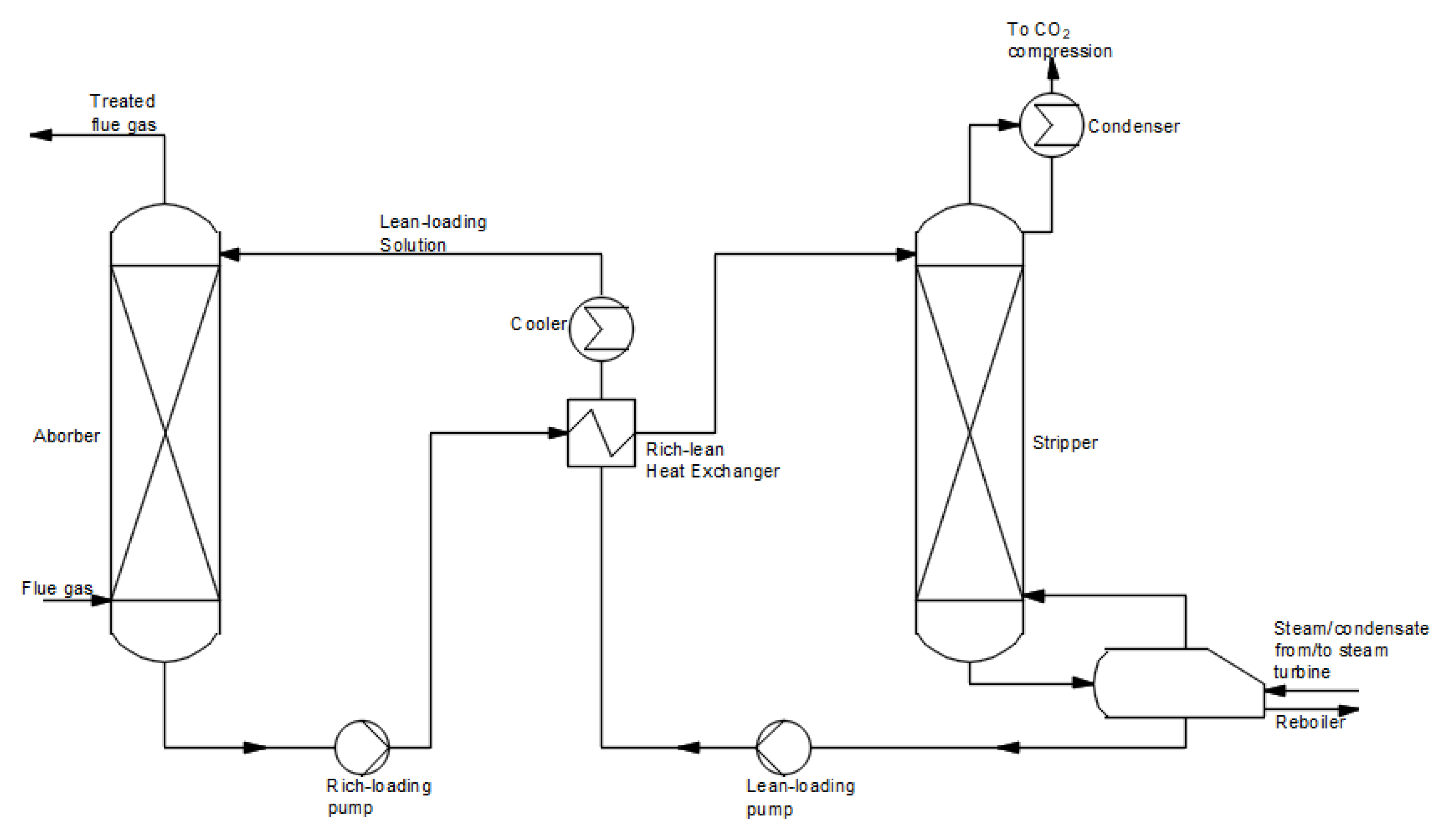
  • (a) Absorption solvent-based methods
Chemical absorption is the most recognizable method of CO2 capture. It relies on a reaction between carbon dioxide and a chemical solvent. Solvents that are usually used are alkanolamines, such as monoethanolamine (MEA), diethanolamine (DEA), or methyl diethanolamine (MDEA) in aqueous solution [16]. A schematic diagram of chemical absorption is shown in Figure 5. The process takes place in two stages. In the first stage, the flue gas reacts with the solvent in the absorber to capture CO2. Subsequently, the rich loading solution is carried to the stripper to regenerate CO2 at elevated temperatures. The solution without CO2 (lean-loading solution) is sent back to the absorber column. A high purity carbon dioxide stream from the desorber is transferred for compression and storage or utilization. The chemical absorption process has been used for a long time in the chemical industry. The typically used 30% MEA and MDEA solutions achieve a high process efficiency and a high degree of carbon dioxide purity [16]. The chemical absorption method is a very energy-consuming process due to the need to supply a large amount of heat to the desorber. It is assumed that approx. 30% (37%) of the heat supplied to the steam in the boiler should be directed to the CCS installation in the case of a steam unit fired with hard coal (lignite), depending on the absorber used (for ammonia, the amount of heat needed for regeneration is 22% for hard coal and 27% for lignite). Chemical absorption technologies are used in power plants fired with solid fuel, and they are the only ones that are commercially available. It is assessed that the amine method can capture approx. 85–95% carbon dioxide included in flue gas with a purity above 99.95% [2].
Figure 5. Scheme of the post-combustion CO2 capture method using a chemical absorption process (based on [15]).
Nowadays, apart from conventional solvents (amine-based-MEA, DEA, ammonia, piperazine), there are other solvents developed for the CO2 capture process. Solvent blends offer the ability to improve absorption properties by combining types properly. Primary and secondary amines have high absorption rates, and tertiary amines are characterized by a high capacity [8]. For example, blending MEA with a little PZ can improve the absorption rate (PZ is 50 times faster than MEA) [17]. Another possibility is to use a solution of 2-amino-2-methyl1-propanol (AMP) promoted with PZ. Artanto et al. showed that a mixture of 25 wt% AMP and 5 wt% PZ can be a good substitution for MEA [18]. Ionic liquids (ILs) are novel alternatives for amines. These low melting salts are comprised of a large organic cation and an arbitrary anion, which can be combined freely, obtaining a great variety of compound properties. ILs can physically or chemically absorb CO2, depending on pressure [8]. A review [19] and articles [17][20] have presented deep insight into this technology. In the case of reducing energy consumption, there are new generation solvents—water-free solvents and biphasic solvents—that have been proposed. The presence of water in a solvent enhances the energy demand for the regeneration process. Novel water-free solvents, such as non-aqueous organic amine blends (methanol, ethylene glycol), aminosilicones, or amines with a superbase have been observed [17]. In [21], researchers showed that solvent mixtures based on ethylene glycol, used in the chemisorption process, can achieve CO2 capture efficiencies of up to 95%. Deep eutectic solvents (DESs), such as choline chloride and ethylene glycol at a 1:2 mole ratio are getting more attention. They are fluids consisting of organic halide salts and metal salts or a hydrogen bond donor. DESs have similar properties to ILs, but they are cheaper and environmentally friendlier. According to [22], using DESs can decrease the vapor pressure of a solvent, achieve a lower effect of corrosion, and needs less energy in the regeneration process.
The physical absorption method is based on using a chemically inert solvent, which absorbs CO2 physically. Absorption occurs in water or organic absorbers (methanol, N-methyl-2-pyrrolidone, dimethyl ether). This method achieves the best results for low temperatures and high pressures of the separated gas. Therefore, it is used to capture CO2 from the coal gasification process. In this method, there are distinguished processes, with the use of solvent such as SelexolTM, RectisolTM, IfpexolTM, FluorTM, PurisolTM, SulfinolTM, and MorphysorbTM [16][17][23].
  • (b) Adsorption–physical separation
Adsorption is a process that uses a solid surface to remove carbon dioxide from a mixture. Physical separation relies on adsorption, absorption, and cryogenic separation methods. It can be physical (Van der Waals forces for adhesion CO2—physisorption) or chemical (covalent bonding between compounds—chemisorption) [24]. Physical adsorption uses various porous materials (such as activated carbon, alumina, metallic oxides, or zeolites [6]) to absorb carbon dioxide. Activated carbons contain amorphous carbon, and it is low-cost material with the advantage of having a large surface area and the possibility of modifying its pore structure. However, the weak binding energy with carbon dioxide causes this material to need to be highly microporous to be useful for carbon capture [8]. Zeolites (crystalline aluminosilicates) have good adsorption properties for CO2 capture, but they are hydrophilic. The presence of water weakens these properties by reducing the strength of interactions between coupled compounds [19]. A new approach is to use metal–organic frameworks (MOFs) in adsorption processes. MOFs consist of metal ions or ion clusters linked by organic ligands and bridges that create strong coordination bonds. On account of this, MOFs are characterized as having benefits such as ease of design and synthesis, a high porosity, and tailored pore properties [25]. One of the other adsorption materials is silica. Silicas are non-carbonaceous substances with a large surface area and pore size, and they are highly mechanically stable. Mesoporous silica materials use amine-based substances for CO2 capture [8][24]. The methods of adsorption are as follows: pressure swing adsorption (PSA), temperature swing adsorption (TSA), vacuum swing adsorption (VSA), and pressure–temperature swing adsorption (PTSA).
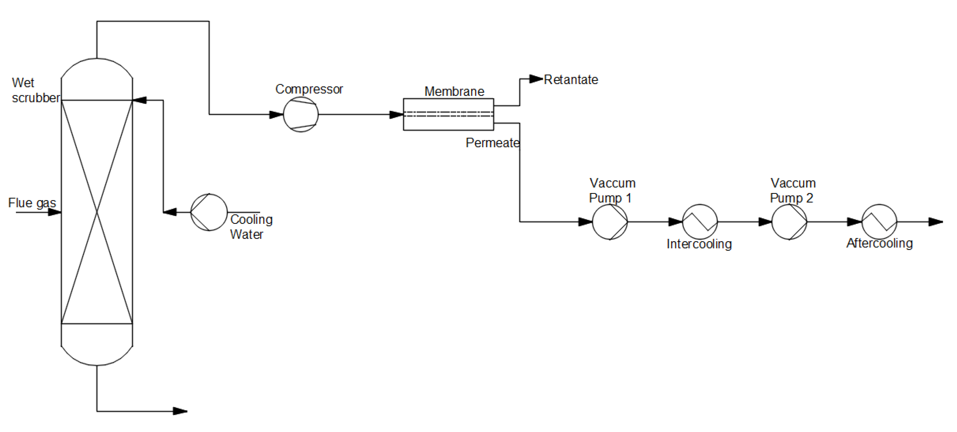
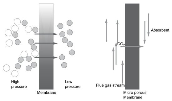
  • (c) Membrane separation
Figure 6 depicts the membrane separation process. In the first place, flue gas is directed to an absorber to cool to the operating temperature of the membrane. Subsequently, flue gas is transported to the membrane. This method uses a spiral wound, flat sheet, and hollow fiber modules [23].
Figure 6. Scheme of the post-combustion CO2 capture method using a membrane separation process (based on [15]).
There are two types of membrane capture technology: gas separation membranes and gas absorption membranes. With a gas separation membrane, gas with CO2 is introduced at the high-pressure side of the membrane. Carbon dioxide is recovered at the low-pressure side. A solid microporous membrane is used to enable gas flow and absorption in the gas absorption system. This system has a high removal rate of CO2, on the grounds of minimization of flooding, foaming, channeling, and entrainment. The principles of both membrane systems are shown in Figure 7 [15][23].
Figure 7. Principle of (left) a gas separation membrane, (right) a gas absorption membrane (based on [23]).
Membranes should characterize relevant properties for gas separation—proper permeability and selectivity. There are three types of membrane materials: polymeric membranes (organic), ceramic membranes (inorganic), and hybrid membranes [15]. A polymeric membrane has a lower cost of production than the others with a relatively high gas flux and it is mechanically stable [26]. Nevertheless, it has generally low selectivity CO2/N2—less than 100, and it is supposed to be 200 [25]. Ceramic membranes, especially zeolites and their derivatives, obtain high selectivities. However, the production of ceramic membranes is more difficult [15]. Hybrid membranes (modified on the surface of inorganic membranes) provide advantages of both membranes, polymeric and ceramic. They have the flexibility and low cost of production of a polymer and the high selectivity of an inorganic material [8][15]. For post-combustion capture, commercially available polymeric membranes, such as PRISM, Polaris, PolyActive, PermSelect, and Medal, are introduced in [27]. A new approach is to use metal–organic frameworks (MOFs) in the experimental stage. These offer many properties that are useful for membranes, such as large surface areas, adjustable pore sizes, and controllable pore-surface properties [25].
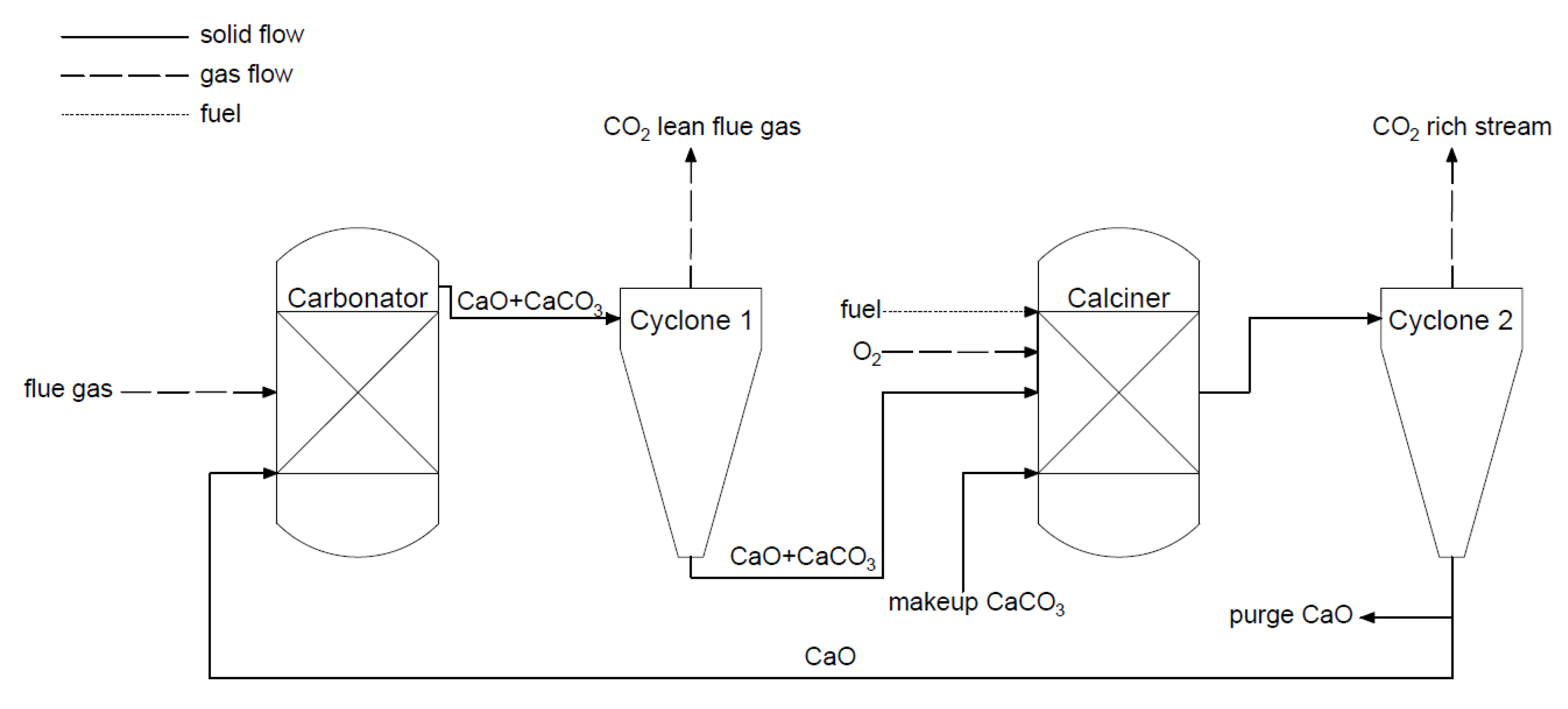
  • (d) Chemical looping combustion (CLC) and calcium looping process (CLP)
Chemical looping technology uses two reactors, an air reactor and a fuel reactor. These reactors typically circulate fluidized beds that are coupled for carrier transport. In the air reactor, oxidation of an “oxygen carrier”, usually metal particles, such as iron, manganese, or copper, occurs with the oxygen from air. As a result of the reaction, metal oxides are formed. These compounds are carried to a second reactor, where they react with the fuel. Metal oxides are reduced during combustion, producing energy and flue gas as a stream of CO2 and H2O. The flue gas can be condensed to receive pure CO2 [28][29].
The calcium looping process is a type of chemical looping. The process (Figure 8) is based on a reversible reaction between calcium oxide and carbon dioxide. The reaction of bounding CaO and CO2 is called carbonation, and takes place in the first reactor. Subsequently, the formed calcium carbonate in the carbonator is transported to the second reactor, called a calciner, where the reversible reaction occurs and high purity CO2 stream is produced (>95%). In the calciner, the heat needed for the reaction is generated by burning fuel in the oxygen atmosphere, and sometimes the CLC capture method is considered a kind of oxy-combustion method. The reactors (circulating fluidized bed (CFB)) are coupled to transport solid and cyclones separate solid and gaseous mass streams. Calcium looping technology has a few advantages. It uses a cheap sorbent (lime) and the flue gas is partially desulfurized. Moreover, the process uses fluidized beds, and this mature high-temperature technology can generate power [6][30].
Figure 8. Scheme of the calcium looping process (adapted from [30]).
  • (e) Cryogenic method
The cryogenic method of carbon capture technology uses liquefied natural gas (LNG) to provide cold energy to capture CO2. Cryogenic CO2 capture is used in oxyfuel combustion technology as well as in post-combustion carbon capture technology to separate CO2 from flue gas. With cryogenic CO2 capture, it is possible to produce high purity CO2 of up to 99.17%. This method includes a few processes, such as compression, expansion, separation, and cooling. The cryogenic method is less preferred because of its high operational cost [31]. The cryogenic method used in post-combustion carbon capture is carried out using various methods [31][32].
  • (f) Application of absorption-based post-combustion capture method
The absorption-based post-combustion capture is the most widely used method due to its efficiency and lower energy consumption. Monoethanolamine (MEA), methyl di-ethanol amine (MDEA) and piperazine (PZ) are the most extensively used amine solvents in large-scale industries [33]. There are many classified technologies used in adsorption and absorption, as well as in membrane separation. Chao et al. analyzed the challenges and compared the commercial use of PCC technology using solvents for absorbents, bed configurations for adsorption, and membrane processes. Among the adsorbent processes, temperature swing adsorption is very effective for both adsorptions, using solid and solvents, compared to pressure swing adsorption (PSA) and vacuum swing adsorption (VSA). TSA is more efficient than PSA and VSA, but it consumes a large amount of energy during regeneration. In the case of chemical absorption, MEA is the best and most used solvent for CO2 capture. MEA shows a good absorption and desorption rate when mixed with other solvents as well. However, the solvent absorption process requires a high energy consumption for the regeneration of solvents, and solvent losses may occur due to evaporation and chemical degradation, leading to reduced absorption capacity [34]. Lungkadee et al. showed simulation analyses of retrofitting a post-carbon capture unit with a 300 MW power plant. The amine-based PCC technology used MEA amine for the carbon capture process, and was estimated to cost less than 55 $/ton of CO2 capture. The absorber and desorber used in this process were designed to have 90% CO2 capture capacity and 30 wt% of MEA. About 63.075 kg/s of CO2 was captured from flue gas at a flow rate of 458 kg/s with 15% CO2 content [35]. Another simulation analysis of natural gas combined cycle (NGCC) power plants with PZ solvent showed better performance when compared to that of MEA solvent. The use of 40 wt% PZ solvent showed significant improvements in capture efficiency, energy consumption, and capture cost compared to that of using 30 wt% MEA solvent. The lowest CO2 capture cost was obtained at 34.65 $/ton of CO2 using 40 wt% PZ solvent [36]. Hadri et al. showed a comparison of 30 different amine solutions (30 wt%) used for post-combustion carbon capture. The amine solutions were analyzed using a solvent screening setup, where amine was passed at 1 bar pressure with a gas containing 15% CO2, and CO2 loading was measured. Compared to that of other amines, hexamethylenediamine had the highest CO2 loading of 1.35 and triethanolamine had the lowest CO2 loading of 0.39 [37].
  • (g) Converting CO2 into value-added chemicals
CO2 can be utilized to satisfy the needs of various industries as fuels and chemicals or beverages and food [38]. Technologies that allow to convert CO2 into value-added chemicals are still being developed because of their economic and environmental benefits. In contrast to physical processes, the valence state of CO2 changes [39]. This process can be used to produce chemical feedstock (polymers, plastics, carbonates [40]), as well as energy carriers (methane, ethane, methanol, syngas). Among the chemical conversions, it is possible to distinguish thermochemical, electrochemical (photoelectrochemical [41]), and biological processes, where enzymes are used [42]. Because of the high stability of CO2, there is a thermodynamic barrier in the CO2 conversion process [43]. A crucial component in most processes connected with converting CO2 into value-added chemicals is hydrogen. It should be produced using renewable energy sources to maintain an environmentally friendly effect.

4. Oxy-Combustion CO2 Capture

The exhaust gas from combustion in an oxygen-enriched atmosphere (oxy-combustion) consists mainly of carbon dioxide and water vapor (nitrogen content is minimized). From the condensation of water vapor, CO2 separation is possible. The condensation temperature is higher than ambient conditions, except for very low partial pressures during the condensation process. The oxygen for combustion is produced using the air separation process, which gives an oxygen purity of about 95%. The general scheme for the process using the oxy-combustion method is presented in Figure 9.
Figure 9. Block diagram of electricity generation heat production with the oxy-combustion CO2 capture method.
Application of oxy-combustion technology mainly concerns solid fuel-fired boilers, including pulverized coal boilers (PCs) or circulating fluidized bed boilers (CFBs), but more and more consideration is being given to the possibility of using oxy-combustion in energy systems with gas turbines. In oxy-combustion technologies, low-temperature and high-temperature boilers can be distinguished. The combustion process in low-temperature boilers usually takes place in oxygen mixed with recirculated exhaust gases. The flame temperatures are similar to those of air-powered units. In the case of high-temperature boilers, the temperature can exceed 2400 °C.
The strengths of oxy-combustion are nitrogen oxide (NOx) reduction, boiler dimension reductions, a simplified CO2 capture method compared to other technologies, the possibility of applying in existing technologies, and less mass flow rate of exhaust gases (about 75% less compared to combustion in air). The weaknesses of oxy-combustion are the high material requirements because of the high temperatures, an efficiency decrease (oxygen production process is energy-consuming), and a high capital cost.
Oxy-combustion methods are mainly used at the laboratory scale, and for pilot installations, among which are the Callide Power Station [44] and Compostilla Thermal Power [45]. A 30 MWe experimental unit in the Callide Power Station started operation in 2012. The nominal flow of 98% pure oxygen, which was supplied to the boiler, was 19,200 mn3/h. Various types of fuel have been the object of investigation (Callide coal, Minerva coal, etc.). Daily production of CO2 based on cryogenic capture technology was 75 t. The unit was closed after a successful demonstration in 2016. A pilot power plant unit with CO2 capture, based on oxy-combustion technology, was developed as part of the OXYCFB 300 project at Compostilla Thermal Power. The CO2 capture installation was equipped with a circulating fluidized bed boiler with thermal power of 30 MWth, and a pulverized coal-fired boiler with thermal power of 20 MWth. The flue gas stream was 800 m3/h. The daily capacity of the separation process, which was carried out using the cryogenic method, was 3–5 tons of CO2.
The development of oxy-combustion technology is not only connected with solid-fired fuel units. It also concerns systems equipped with gas turbines, where combustion in an oxygen-enriched atmosphere takes place. Within the framework of the project Negative CO2 Emission Gas Power Plant [46][47], the concept of a negative CO2 emission gas power plant based on oxy-combustion combined with CO2 capture from flue gas was developed. Application of CO2 neutral fuel, such as sewage sludge in combination with oxy-combustion and CO2 capture, will allow negative emission levels [48]. The CO2 capture process will be possible, among other things, through the use of a prototype spray-ejector condenser (SEC). The main task of the SEC will be to condense the water vapor from the exhaust gases.
Among other CO2 capture technologies, oxy-combustion carbon capture does not require many process modifications. Oxygen is used for the combustion process instead of air to eliminate the nitrogen content in flue gas, which leaves flue gas with carbon dioxide and water vapor as the major contents. This flue gas does not require high energy consumption for CO2 separation. The boiler’s temperature is controlled by again sending part of the flue gas (about 70%) to the boiler. The air separation unit (ASU), which separates oxygen from air, is the most energy-consuming part of the oxyfuel combustion process. An industrial-scale cryogenic ASU consumes up to 200–225 kWh/t on an industrial scale [49]. To improve efficiency and CO2 capture, oxyfuel combustion carbon capture is combined with moderate and intense low-oxygen dilution (MILD). MILD oxy-combustion carbon capture (MOFC) holds many benefits, such as improving the efficiency of the plant, improving the purity of the CO2, and reducing energy consumption [12]. The oxy-fuel combustion CCS technology used in the Allam cycle shows a higher efficiency of 55–59%, which is higher when compared to that of a combined cycle power plant with a carbon capture unit. In the Allam cycle, the heat generated from the ASU is sent to the regenerator to heat up the CO2 to 400 °C, which is then reused in the combustion chamber, improving the cycle efficiency [50].

References

  1. Spliethoff, H. Power Generation from Solid Fuels; Springer: Berlin/Heidelberg, Germany, 2010.
  2. Chmielniak, T. Technologie Energetyczn, 2nd ed.; Wydawnictwo Naukowe PWN: Warszawa, Poland, 2021.
  3. Sarkar, S. Fuels and Combustion; University Press: New Delhi, India, 2009.
  4. Madejski, P. (Ed.) Thermal Power Plants, New Trends and Recent Developments; Intech Open Limited: London, UK, 2018; ISBN 978-1-78923-079-6.
  5. Madejski, P.; Janda, T.; Modliński, N.; Nabagło, D. A Combustion Process Optimization and Numerical Analysis for the Low Emission Operation of Pulverized Coal-Fired Boiler. In Developments in Combustion Technology; Kyprianidis, K., Skvaril, J., Eds.; In Intech Open Limited: London, UK, 2016.
  6. Energy Technology Perspectives 2020, Special Report on Carbon Capture Utilisation and Storage CCUS in Clean Energy Transitions; IEA: Paris, France, 2020; Available online: https://iea.blob.core.windows.net/assets/7f8aed40-89af-4348-be19-c8a67df0b9ea/Energy_Technology_Perspectives_2020_PDF.pdf (accessed on 2 December 2021).
  7. Centrum Informacji o Rynku Energii, Cena Emisji CO2 Może Wzrosnąć o Ponad 50% do 2030—Wynika z Projektu UE. Available online: https://www.cire.pl/artykuly/materialy-problemowe/186670-cena-emisji-co2-moze-wzrosnac-o-ponad-50-do-2030-wynika-z-projektu-ue (accessed on 20 October 2021).
  8. Nord, L.; Bolland, O. Carbon Dioxide Emission Management in Power Generation; Wiley-VCH Verlag GmbH & Co.: Weinheim, Germany, 2020.
  9. Peridas, G.; Mordick Schmidt, B. The role of carbon capture and storage in the race to carbon neutrality. Electr. J. 2021, 34, 106996.
  10. Wienchol, P.; Szlȩk, A.; Ditaranto, M. Waste-to-energy technology integrated with carbon capture—Challenges and opportunities. Energy 2020, 198, 117352.
  11. Holz, F.; Scherwath, T.; del Granado, P.C.; Skar, C.; Olmos, L.; Ploussard, Q.; Ramos, A.; Herbst, A. A 2050 perspective on the role for carbon capture and storage in the European power system and industry sector. Energy Econ. 2021, 104, 105631.
  12. Gładysz, P.; Stanek, W.; Czarnowska, L.; Sładek, S.; Szlęk, A. Thermo-ecological evaluation of an integrated MILD oxy-fuel combustion power plant with CO2 capture, utilisation, and storage—A case study in Poland. Energy 2018, 144, 379–392.
  13. Theo, W.L.; Lim, J.S.; Hashim, H.; Mustaffa, A.A.; Ho, W.S. Review of pre-combustion capture and ionic liquid in carbon capture and storage. Appl. Energy 2016, 183, 1633–1663.
  14. Olabi, A.G.; Obaideen, K.; Elsaid, K.; Wilberforce, T.; Sayed, E.T.; Maghrabie, H.M.; Abdelkareem, M.A. Assessment of the pre-combustion carbon capture contribution into sustainable development goals SDGs using novel indicators. Renew. Sustain. Energy Rev. 2022, 153, 1117102022.
  15. Wanga, Y.; Zhaoa, L.; Ottoa, A.; Robiniusa, M.; Stoltena, D. A Review of Post-combustion CO2 Capture Technologies from Coal-fired Power Plants. Energy Procedia 2017, 114, 650–665.
  16. Kuropka, J. Możliwości Ograniczania Emisji Ditlenku Węgla ze Spalin Energetycznych. Available online: http://www.pzits.not.pl/docs/ksiazki/Pol_%202012/Kuropka%20179-188.pdf (accessed on 18 October 2021).
  17. Vega, F.; Cano, M.; Camino, S.; Fernandez, L.M.G.; Portillo, E.; Navarrete, B. Solvents for Carbon Dioxide Capture. In Carbon Dioxide Chemistry, Capture and Oil Recovery; Intechopen: London, UK, 2018; ISBN 978-1-78923-575-3.
  18. Artanto, Y.; Jansen, J.; Pearson, P.; Puxty, G.; Cottrell, A.; Meuleman, E.; Feron, P. Pilot-scale evaluation of AMP/PZ to capture CO2 from flue gas of an Australian brown coal–fired power station. Int. J. Greenh. Gas Control 2014, 20, 189–195.
  19. Boot-Handford, M.; Abanades, J.C.; Anthony, E.J.; Blunt, M.J.; Brandani, S.; Mac Dowell, N.; Fernández, J.R.; Ferrari, M.-C.; Gross, R.; Hallett, J.P.; et al. Carbon capture and storage update. Energy Environ. Sci. 2014, 7, 130–189.
  20. Bui, M.; Adjiman, C.S.; Bardow, A.; Anthony, E.J.; Boston, A.; Brown, S.; Fennell, P.S.; Fuss, S.; Galindo, A.; Hackett, L.A.; et al. Carbon capture and storage (CCS): The way forward. Energy Environ. Sci. 2018, 11, 1062–1176.
  21. Barzgali, F.; Lai, S.; Mani, F. Novel non-aqueous amine solvents for reversible CO2 capture. Energy Procedia 2014, 63, 1795–1804.
  22. Mahi, M.; Mokbel, I.; Negadi, L.; Dergal, F.; Jose, J. Experimental solubility of carbon dioxide in monoethanolamine, or diethanolamine or N-methyldiethanolamine (30 wt%) dissolved in deep eutectic solvent (choline chloride and ethylene glycol solution). J. Mol. Liq. 2019, 289, 111062.
  23. Sifat, N.S.; Haseli, Y. A critical review of CO2 Capture Technologies and Prospects for Clean Power Generetion. Energies 2019, 12, 4143.
  24. Osman, A.I.; Hefny, M.; Maksoud, M.I.A.A.; Elgarahy, A.M.; Rooney, D.W. Recent advances in carbon capture storage and utilisation technologies: A review. Environ. Chem. Lett. 2020, 19, 797–849.
  25. Li, J.-R.; Ma, Y.; McCarthy, M.C.; Sculley, J.; Yu, J.; Jeong, H.-K.; Balbuena, P.B.; Zhou, H.-C. Carbon dioxide capture-related gas adsorption and separation in metal-organic frameworks. Coord. Chem. Rev. 2011, 255, 1791–1823.
  26. Pires, J.C.M.; Martins, F.G.; Alvim-Ferraz, M.C.M.; Simões, M. Recent developments on carbon capture and storage: An overview. Chem. Eng. Res. Des. 2011, 89, 1446–1460.
  27. Kárászová, M.; Zach, B.; Petrusová, Z.; Červenka, V.; Bobák, M.; Šyc, M.; Izák, P. Post-combustion carbon capture by membrane separation, Review. Sep. Purif. Technol. 2020, 238, 116448.
  28. Rakowski, J.; Bocian, P.; Celińska, A.; Świątkowski, B.; Golec, T. Zastosowanie Pętli Chemicznej w Energetyce. Available online: http://elektroenergetyka.pl/upload/file/2016/4/Rakowski_04_2016.pdf (accessed on 15 October 2021).
  29. Bhavsar, S.; Najera, M.; More, A.; Veser, G. Chemical-looping processes for fuel-flexible combustion and fuel production. In Reactor and Process Design in Sustainable Energy Technology, 1st ed.; Elsevier B.V.: Amsterdam, The Netherlands, 2014; pp. 233–280.
  30. Tilak, P.; El-Halwagi, M.M. Process integration of Calcium Looping with industrials plants for monetizing CO2 into value-added products. Carbon Resour. Convers. 2018, 1, 191–199.
  31. Knapik, E.; Kosowski, P.; Stopa, J. Cryogenic liquefaction and separation of CO2 using nitrogen removal unit cold energy. Chem. Eng. Res. Des. 2018, 131, 66–79.
  32. Song, C.; Liu, Q.; Deng, S.; Li, H.; Kitamura, Y. Cryogenic-based CO2 capture technologies: State-of-the-art developments and current challenges. Renew. Sustain. Energy Rev. 2019, 101, 265–278.
  33. Mostafavi, E.; Ashrafi, O.; Navarri, P. Assessment of process modifications for amine-based post-combustion carbon capture processes. Clean. Eng. Technol. 2021, 4, 100249.
  34. Chao, C.; Deng, Y.; Dewil, R.; Baeyens, J.; Fan, X. Post-combustion carbon capture. Renew. Sustain. Energy Rev. 2021, 138, 110490.
  35. Lungkadee, T.; Onsree, T.; Tangparitkul, S.; Janwiruch, N.; Nuntaphan, A.; Tippayawong, N. Technical and economic analysis of retrofitting a post-combustion carbon capture system in a Thai coal-fired power plant. Energy Rep. 2021, 7, 308–313.
  36. Otitoju, O.; Oko, E.; Wang, M. Technical and economic performance assessment of post-combustion carbon capture using piperazine for large scale natural gas combined cycle power plants through process simulation. Appl. Energy 2021, 292, 116893.
  37. El Hadri, N.; Quang, D.V.; Goetheer, E.L.V.; Abu Zahra, M.R.M. Aqueous amine solution characterization for post-combustion CO2 capture process. Appl. Energy 2017, 185, 1433–1449.
  38. Zhang, Z.; Pan, S.-Y.; Li, H.; Cai, J.; Olabi, A.G.; Anthony, E.J.; Manovic, V. Recent advances in carbon dioxide utilization. Renew. Sustain. Energy Rev. 2020, 125, 109799.
  39. Agarwal, A.S.; Rode, E.; Sridhar, N.; Hill, D. Conversion of CO2 to Value-Added Chemicals: Opportunities and Challenges. In Handbook Climate Change Mitigigation and Adaptation; Chen, W.Y., Suzuki, T., Lackner, M., Eds.; Springer: New York, NY, USA, 2015; pp. 1–40.
  40. Pal, T.K.; De, D.; Bharadwaj, P.K. Metal–organic frameworks for the chemical fixation of CO2 into cyclic carbonates. Coord. Chem. Rev. 2020, 408, 213173.
  41. Kumaravel, V.; Barlett, J.; Pillai, S.C. Photoelectrochemical Conversion of Carbon Dioxide (CO2) into Fuels and Value Added Products. ACS Energy Lett. 2020, 5, 486–529.
  42. McGrath, O.J. Biological Conversion of Carbon Dioxide to Value-Added Chemicals. Grad. Thesis Diss. Probl. Rep. 2021, 8293.
  43. Nocito, F.; Dibenedetto, A. Atmospheric CO2 mitigation technologies: Carbon capture utilization and storage. Curr. Opin. Green Sustain. Chem. 2020, 21, 34–43.
  44. CS Energy, Callide Oxyfuel Project. Available online: https://www.csenergy.com.au/what-we-do/generating-energy/callide-power-station/callide-oxyfuel-project (accessed on 20 October 2021).
  45. Global CCS Institue. The Compostilla Project OXYCFB300. Available online: https://www.globalccsinstitute.com/archive/hub/publications/137158/Compostilla-project-OXYCFB300-carbon-capture-storage-demonstration-project-knowledge-sharing-FEED-report.pdf (accessed on 20 October 2021).
  46. Project Negative CO2 Emission Gas Power Plant. Available online: https://nco2pp.mech.pg.gda.pl (accessed on 20 October 2021).
  47. Ziółkowski, P.; Madejski, P.; Amiri, M.; Kuś, T.; Stasiak, K.; Subramanian, N.; Pawlak-Kruczek, H.; Badur, J.; Niedźwiecki, Ł.; Mikielewicz, D. Thermodynamic Analysis of Negative CO2 Emission Power Plant Using Aspen Plus, Aspen Hysys, and Ebsilon Software. Energies 2021, 14, 6304.
  48. Ziółkowski, P.; Badur, J.; Pawlak-Kruczek, H.; Niedzwiecki, L.; Kowal, M.; Krochmalny, K. A novel concept of negative CO2 emission power plant for utilization of sewage sludge. In Proceedings of the 6th International Conference on Contemporary Problems of Thermal Engineering CPOTE 2020, Gliwice, Poland, 21–24 September 2020; pp. 531–542.
  49. Cormos, C.C. Oxy-combustion of coal, lignite and biomass: A techno-economic analysis for a large scale Carbon Capture and Storage (CCS) project in Romania. Fuel 2016, 169, 50–57.
  50. Kindra, V.; Rogalev, A.; Lisin, E.; Osipov, S.; Zlyvko, O. Techno-economic analysis of the oxy-fuel combustion power cycles with near-zero emissions. Energies 2021, 14, 5358.
More
Information
Contributors MDPI registered users' name will be linked to their SciProfiles pages. To register with us, please refer to https://encyclopedia.pub/register : , , ,
View Times: 11.1K
Revisions: 4 times (View History)
Update Date: 15 Feb 2022
1000/1000