1. Waelz Kiln
The Waelz process is currently the most widely used method for recovering those dusts containing medium levels (16–30 wt.%) of zinc; the vast literature may be found about this technology and eventual improvements will be carried out
[1][2][3][4][5][6], and a simplified flow scheme is reported in
Figure 1 below.
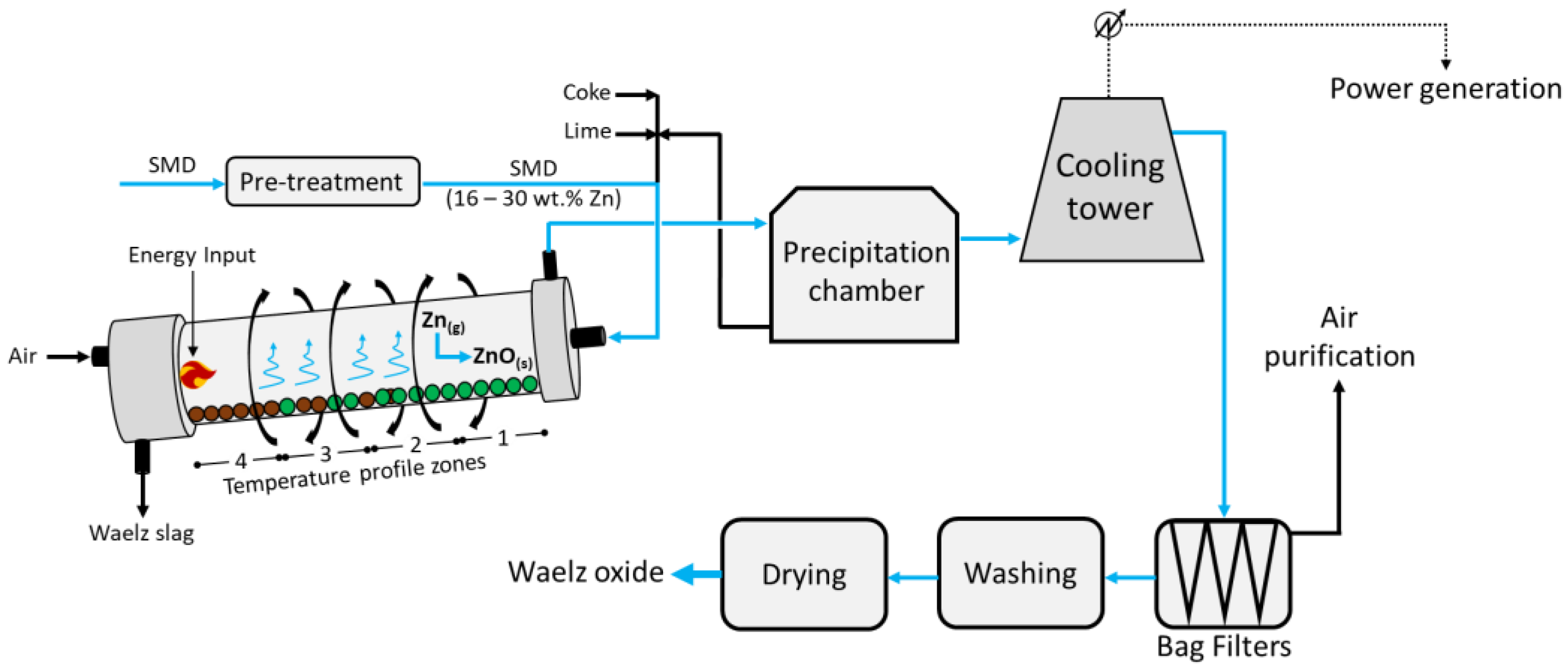
The feed, composed of pelletized Zn-rich dusts/coke/lime agglomerates, enters at the head of the rotating (~1 rpm) and 2–3% inclined Waelz kiln; despite the different designs, it is usually 50 m long with an inner diameter of about 3.5 m. The kiln has a precise temperature profile which is reported in
Figure 1 as zone 1 (600 °C), zone 2 (1100 °C), zone 3 (1300 °C), and zone 4 (1000 °C). The feed occurs in the upper zone 1, whereas counter-current air is injected from the bottom (zone 4); here, the solids achieve a maximum temperature of about 1250 °C. Such operating temperatures fully depend on the chemical composition of the feed; in fact, while too low temperatures would hinder the reduction of zinc, too high values would lead to clumping and products with a lower surface area. In zone 1, the pre-heating and drying of the feed is carried out, while the higher temperature in zone 2 allows for the combustion of the coke, the Boudouard equilibrium (Equation (1)), and the reduction in Fe and Pb in the melt (Equations (2)–(5) below)
[7].
In zone 3, the reduction in ZnO to metal vapour Zn (Equation (6)) occurs, while zone 4 provides further thermal energy due to the combustion of the residual carbon in the charge, and the partial reoxidation of Fe occurs.
Finally, the vapor metals Zn and Pb are oxidized back to ZnO and PbO, respectively, and exit the kiln from zone 1 at around 700 °C, pre-heating the feed, while the Waelz slag is collected at the bottom of zone 4. Following, the gaseous mixture vented from zone 1 enters a precipitation chamber where coarse dust with medium Zn contents is collected at the bottom and is recirculated into the kiln alongside the fresh feed. The resulting vapors then undergo cooling to about 200 °C and enter the bag filters, from which a dust rich in Zn is collected at the bottom and air leaves at the top and is further purified. Finally, the solids are washed, dried, and high-purity ZnO is obtained.
Despite the large treatment capacity and the relatively good economic return, the main disadvantages are represented by the medium-to-high Zn content (16–30 wt.%) required in the feed, the additional flux (CaO or MgO) needed in the feed to prevent ring formation in the kiln, which leads to a higher gangue content in the slag, and a large amount of Waelz slag (approximately 80% in mass of the total products) still contaminated with Zn and Pb (and therefore mainly landfilled without recovery of these valuable metals, therefore excluded from material cycles). Given the coke consumption reported in the literature (0.4 t
Coke/t
EAFD [8]), the emission factor of 3.3 t
CO2/t
Coke and the heating value of 8.3 MWh/t
Coke [DIN EN 19694-2], the Waelz process emits about 1.2 t
CO2 and consumes up to 3.0 MWh for each ton of EAFD processed. The coke making process is excluded here from this energy and carbon balance, carried out via the CSN EN 19694-2
[9].
2. Rotary Hearth Furnace (RHF)
The RHF process is widely used to process dusts for the recovery of Zn and Pb, while generating a secondary stream of direct reduced iron-DRI
[10] to be reused in the steelmaking process
[11][12][13]; an overview of the main operational units and material flows is depicted below in
Figure 2.
As a representative of advanced design, the commercially available reheating furnaces from Tenova
[14] may process up to 250 t/h of billet/blooms, with a diameter and length ranging between 0.2–0.45 m and 1.4–5.5 m, respectively. The RHF would occupy a large portion of the steelwork, given the average diameter of the furnace at 45 m and more; it generally requires the supply of 5.5 MWh (of which 4.2 MWh is from coal combustion) and this leads to the emission of 1.3 t
CO2 per ton of DRI obtained
[11], calculated through the CSN EN 19694-2 standard.
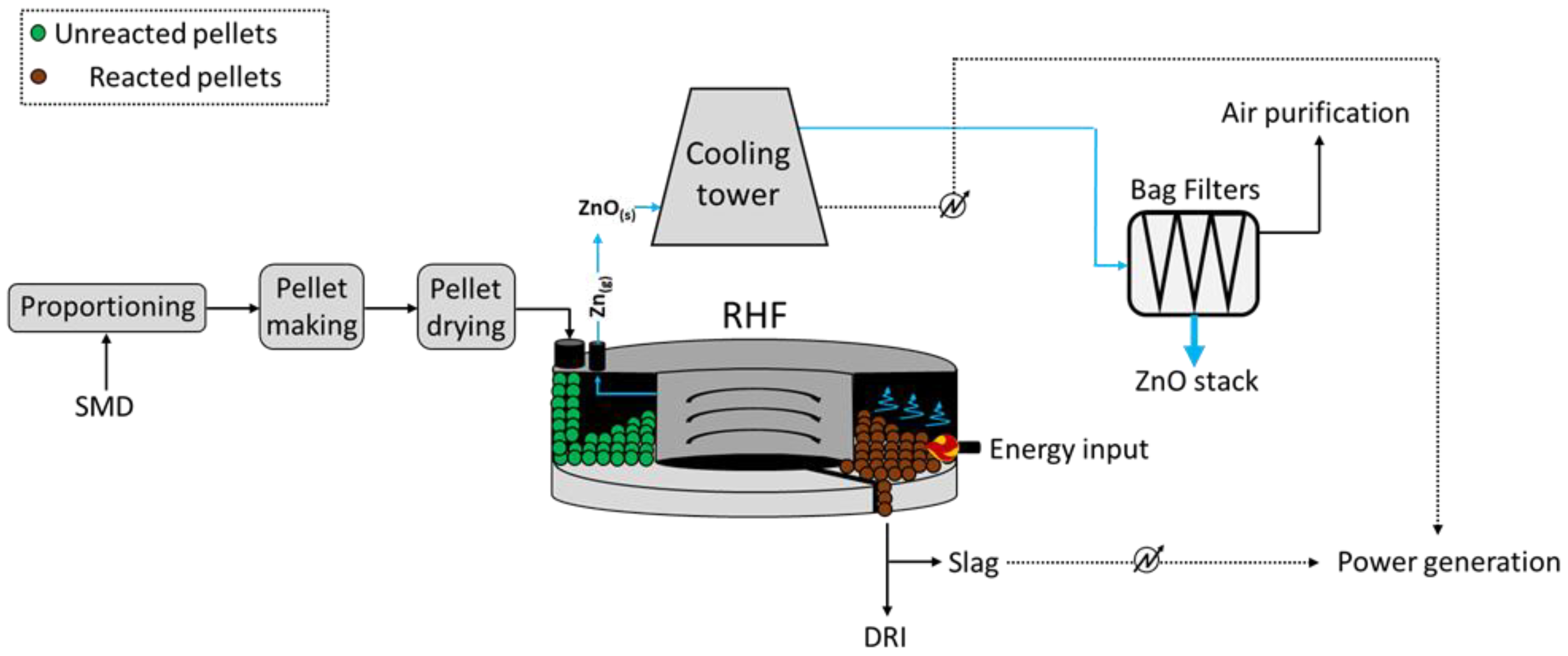
As reported, the process is composed of five main steps, such as the proportioning of the feed, i.e., dusts, reducing agent (coke), and a flux (CaO), pelletization, iron direct reduction, flue gas treatment, and Zn recovery. Prior to RHF, the Zn-rich dusts and sludges require a pre-treatment which mostly depends on the moisture of the materials. The low-to-medium moisture dusts and sludges are easy to treat, whereas those with high moisture imply technical (formation of rigid and free-of-deformations agglomerates) and economic (efficiency of the water removal) issues
[12].
To ensure the homogeneous heating of the pellets within the circular furnace, these are inserted evenly on the belt conveyor, where the direct reduction in iron occurs at 1250–1300 °C at a residence time ranging between 10 and 20 min. Such DRI may be returned to the steelwork process upon pre-treatment. At the same time, the zinc oxides in the feed are reduced and Zn vapors are released and conveyed towards a heat exchanger at first, where energy is recovered in the combustion air, and the oxidation of Zn occurs upon contact with cooling air. Following, such stream is conveyed to bag filters, which allow for the collection of Zn-rich (40–70 wt.% ZnO) coarse dust.
Overall, the RHF process is an effective method to recover Zn and Fe from dusts, since it operates at a lower energy intensity, with respect to the Waelz process, and therefore reflects a lower environmental burden. However, despite the relatively simple functioning and low maintenance needs, the large equipment area needed for the operations and the high initial investments represent significant obstacles for its application, therefore requiring further implementation.
3. OxyCup Furnace
The pyrometallurgical OxyCup process also allows the recovery of Zn from dusts and other streams from traditional (both ISM and EAF) steelwork industry, while separating and valorizing the iron present in the feed to recirculate it for steel production
[15]. It was developed by the company Kuttner GmbH & Co.
[16] and realized at industrial scale by Thyssen-Krupp Steel in 2004 in Duisburg, where up to about 500 t/d of agglomerated ferrous dusts and sludges are currently recycled. In China, TISCO erected a double OxyCup plant in 2011 for the treatment of stainless-steel dusts, sludges, and skulls, generating about 850 tHM/d
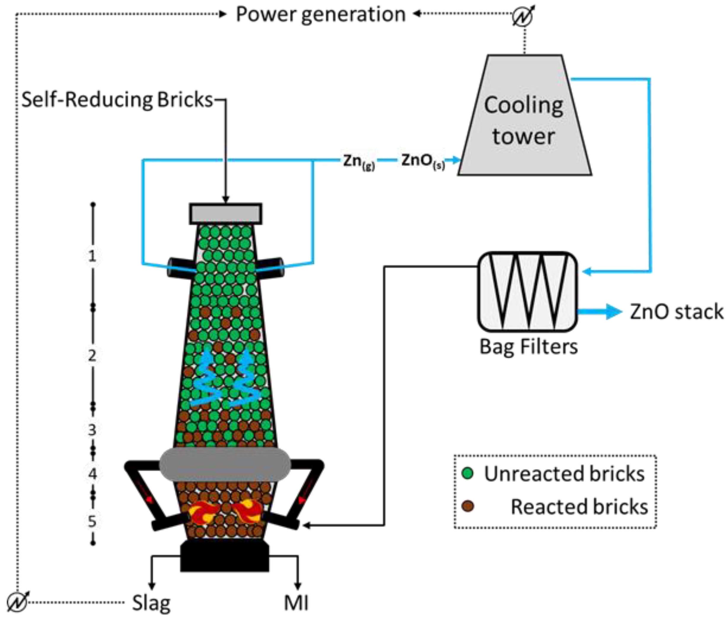
[17]. The crucial unit of the process is an oxygen-enriched cupola furnace, similar but smaller than the traditional BF used in the ISM cycle. It is fed with self-reducing bricks appropriately assembled from sludge, dust, and scale residues, with an iron content of around 45 wt.%. To ensure an effective reducing action of the bricks, a relatively high carbon content (~15 wt%) is introduced in the bricks upon manufacturing with water and cement, therefore including discrete amounts of flux agent (CaO around 10 wt.%); the bricks are fed together with desulphurization skulls, BOF skulls, coke, and gravel. The brick-making process is of crucial importance for the successful operation of the OxyCup; it implies the coordinated action of three main sections, which imply the handling of the materials into the respective silos, the material dosing through the use of a vibrating press, and the curing/hardening of such bricks prior to feed. The overall scheme of the process might be observed in
Figure 3 below, which highlights the path of Zn in the input and output materials
[15]. The lowest section of the furnace (
Figure 3) is filled with the reducing agent, generally coke, to allow the achievement of high temperatures (up to 2500 °C) through hot blast injection via water-cooled lances at both sides of the unit. The annular chamber between sections 4 and 3 (at temperatures of 1800 °C and 1400 °C, respectively) collects part of the exhaust gases arising from the combustion at the bottom, retaining most of the unburned/partially burned ash and re-injecting it at the level of the lances; doing so, a smoke-free upper section is ensured. The reduction in Fe, Zn, Pb, and alkalis starts in section 2 (approximately 1000 °C; while the molten metal descends the furnace, the Zn (blue highlighted) and the Pb metal vapors climb the unit and leave it in zone 1 (around 300 °C). Such gas is firstly water scrubbed and then interacts with air to convert metal the Zn to ZnO, which is finally separated though the action of opportune bag filters, from which one part of the combustion air is recirculated, and another part is further processed and released to the atmosphere. With respect to the BF operation, the Oxycup furnace implies a hot blast at a lower temperature (around 650 °C) but with higher oxygen content (generally 30 vol.%), allowing for a higher energy efficiency. Moreover, the molten iron (MI) and the slag at the bottom are continuously tapped and separated through a siphon unit.
The OxyCup is very flexible, ideally allowing for a 100% feed of bricks, with an iron content ranging between 40 and 50%; the sludges arising from the treatment of the dusts are relatively rich in Zn (30%), and therefore further treatable. Limiting the balance solely to the coke consumption, the OxyCup process consumes about 0.3 tcoke/tHM, therefore resulting in 1.1 tCO2 emitted and 2.8 MWh consumed per ton of HM recovered (calculated through the CSN EN 19694-2 standard).
4. DK Process (Shaft Furnaces)
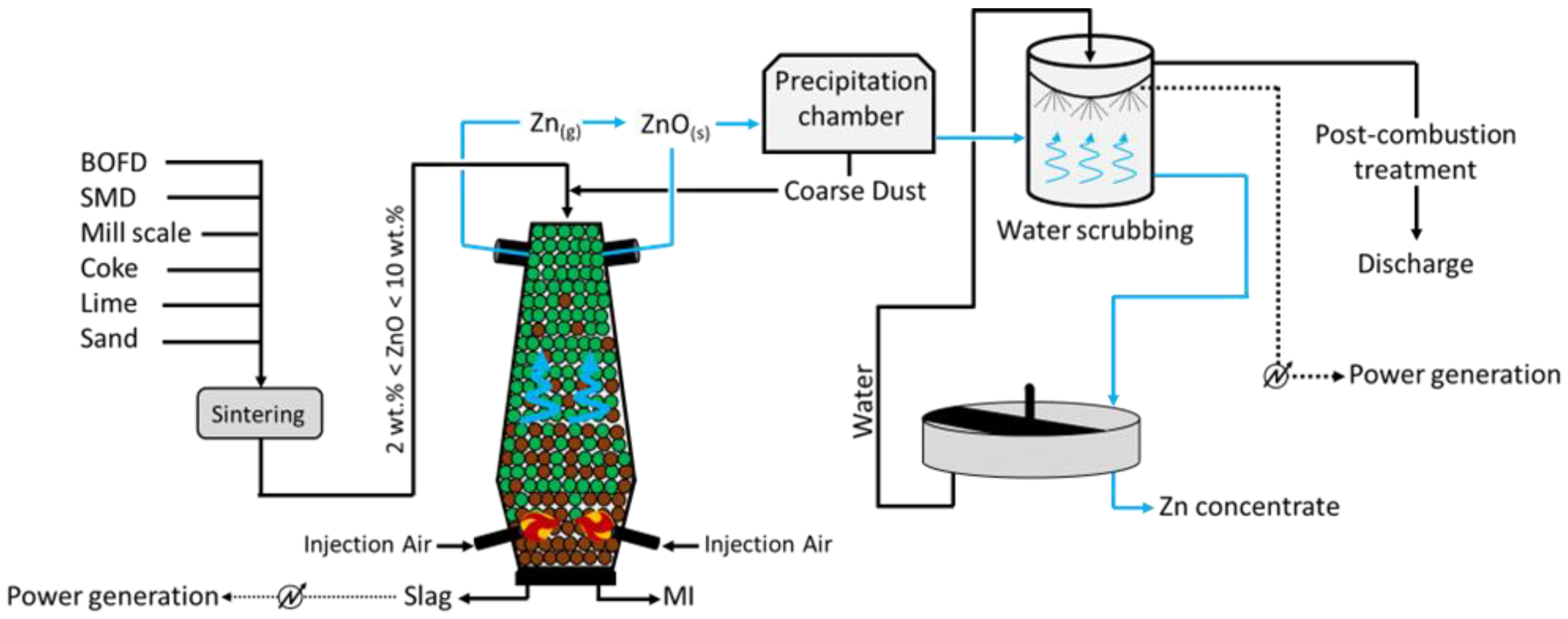
The DK process (
Figure 4) was first applied by the company DK Recycling and Roheisen in Duisburg (Germany); it implies two smaller-scale BF units of different volumes (580 m
3 and 460 m
3, with an output capacity of 1000 and 500 tHM/d, respectively), alternatively operated and opportunely designed to treat a precise quality of feed. In fact, the residues treated are significantly rich in Fe and Zn (up to 60 wt.%), with the raw material mix being generally composed of BOFD (52.5%), mill scale (12.8%), iron ore (7.6%), BF sludge (5.4%), BOF sludge (5.0%), and others (16.3%, including coke breeze and sand)
[18]. Apart from the Zn- and Fe-rich steel streams, i.e., BOD, mill scale, and other raw materials are selected to ensure the generation of resistant (lime and quartz) pellets, which would promptly ignite (coke). To do so, such solids firstly undergo a high-temperature sintering process and then they are fed to the furnace for smelting. The charge is fed at the top of the furnace, while the blast is applied through two tuyeres at the bottom of the unit. The temperature of the gas decreases towards the top of the furnace (approximately 300 °C), while the system achieves values above 1800 °C at the bottom, where strongly reducing conditions are also obtained. The slag and liquid metal (MI) are collected at the bottom of the unit, while the off gas, together with the reduced Zn in a vapor state ascend the furnace and are oxidized (Zn (g) + CO
2 (g) → ZnO (s) + CO (g)) prior to being conveyed in a precipitation chamber where coarse dust, still with small contents of Zn and Fe, is collected and recycled at the top of the furnace. The Zn-rich finer fraction leaving the precipitation chambers undergoes water scrubbing, during which ZnO dissolves and is collected in the liquid stream at the bottom of the unit. Apart from removing Zn from the gas phase, heat is also recovered and used to internally produce power. The remaining of the gas is finally discharged to the atmosphere upon further post-combustion treatment, aimed to remove traces of heavy metals and CO
2. Finally, the Zn-rich liquid stream arising from the scrubbing is concentrated in a thickening unit, and a 65–68 wt.% Zn pulp is separated from the water, which is reused for water scrubbing.
Given the robust technology and the high feasibility in terms of retrofitting with the pre-existing steel plants, the application of the DK process looks promising, also considering the concentrated Zn, which may be obtained. However, the process has a high carbon footprint (about 2.5 tCO
2/tPigIron
[19]) together with the frequent maintenance needed in the furnace to prevent blocking and malfunctioning linked to the significant Zn and alkali contents, represent the main drawbacks of such technology.
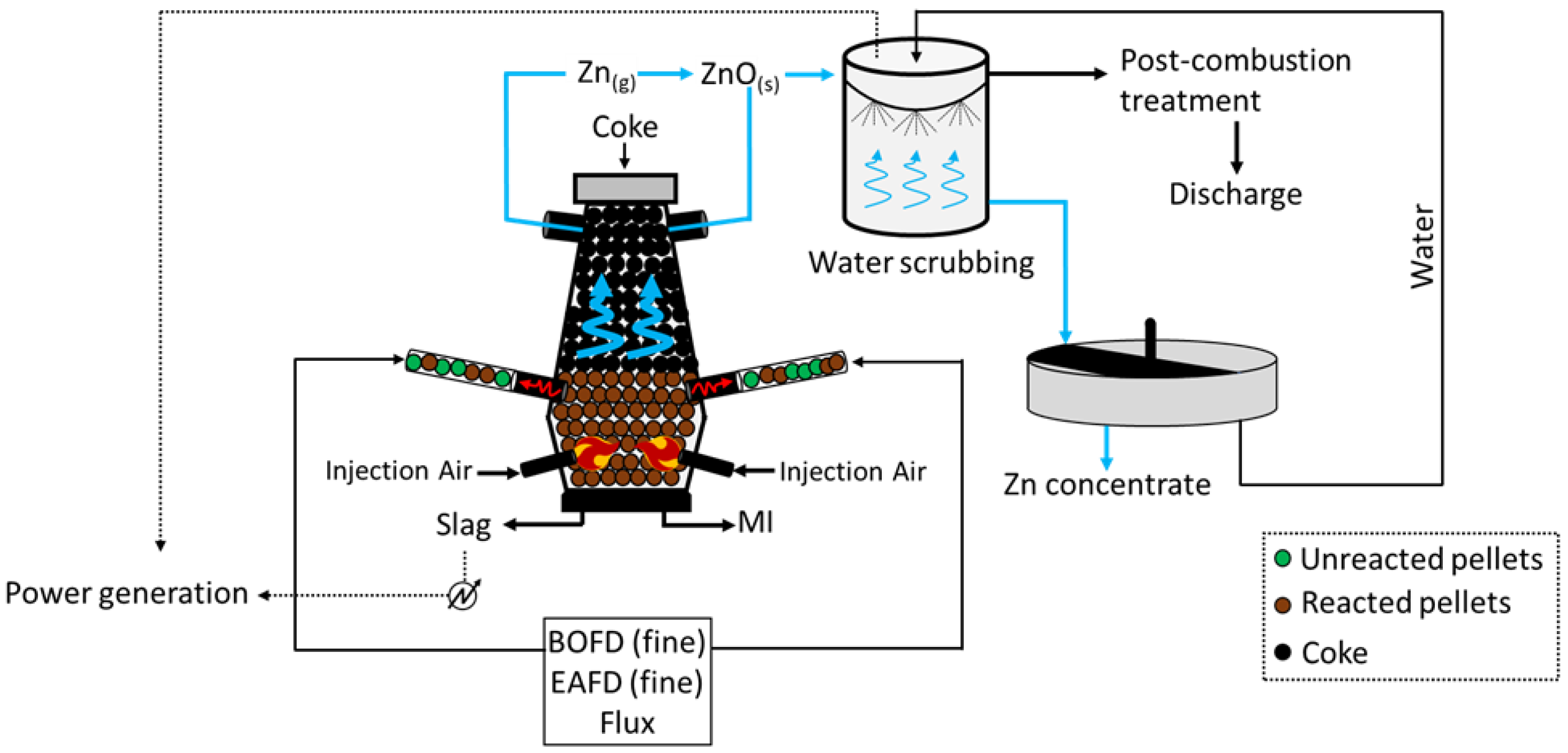
5. Coke-Packed Bed Furnace
The coke-packed bed process is a melting–reduction pyrometallurgical process developed by Kawasaki Steel Corp., which is used to recover Zn and Fe from steelmaking (EAF and BF/BOF) dusts. Originally, such smelting reduction process was applied to the production of ferro-alloys from fine ores
[20], but it has been differently evaluated given the possibility of (1) directly using fine raw materials without agglomeration, (2) recovering nearly the whole zinc and lead contents, (3) and avoiding waste at all
[21]. The overall flow scheme is reported in
Figure 5, where the path of Zn is highlighted blue. As reported, the upper part of the furnace is packed with coke, which is continuously fed from the top. It ensures the effective reducing power necessary for the reduction in the oxides by descending the furnace and combusting. However, the substantial difference, with respect to the other furnace-based processes, is that here the feed is in powder form; therefore, the energy emissions related to the sintering operations can be avoided. Overall, four tuyeres are used in this configuration, all located in the bottom section of the furnace; while the bottom ones allow for the insertion of the blast, sustaining the combustion, the upper ones allow the entrance of the feed. This configuration allows for the achievement of high temperatures (1600 °C) and reducing conditions in the region located between the upper and bottom tuyeres, leading to the partial melting of the oxides even before entering the unit. As for the previous processes, the metals with high boiling points will melt and descend the unit, being collected as liquid iron (MI) or slag
[22], whereas those with low boiling points, i.e., Zn, will pass to the vapor phase and will exit the unit at the top together with the off gas. Such gas stream is firstly oxidized, and therefore Zn vapor passes to ultra-fine ZnO dust, and enters a water scrubbing unit which promotes the dissolution of ZnO in water and its removal from the gas phase. Heat is also recovered at this stage, since the off gas leaves the furnace at around 700 °C, and power can be produced for internal use; prior to discharge, the gases are finally pre-treated, while a Zn concentrate can be obtained from the liquid stream processed in the thickening unit.
This process allows for an effective separation of Zn from Fe and a high recovery rate, without the need to significantly pre-treat the feed; however, the process uses large amounts of coke (1.1 tCoke/tHM), resulting in significant energy consumptions (8.9 MWh/tHM) and carbon emissions (3.5 tCO
2/tHM)
[21] (calculated through the CSN EN 19694-2 standard). The replacement of coke with biomass could allow for the mitigation of such carbon emissions; however, clumping issues might severely affect the functioning of the unit
[23].
6. Other Processes
Primus
[24] is a direct reduction process for treating EAFD. The primus process is suitable for treating metallurgical solid waste with zinc containing more than 5 wt.% and recovering valuable metals, such as BFD, BFS, BOD, EAFD and sludge, or dust generated by small rolling mills. The main feature of this process is to use multi-hearth technology. Primus’s reaction furnace consists of cylindrical chambers with multiple stacked annular compartments to form a multi-stage furnace.
Romelt’s
[25] process for ironmaking is a smelting reduction process to produce hot metal. Romelt’s process can treat any iron containing material, e.g., iron ore fines and concentrates, BF and BOF dusts and sludges, mill scale, iron bearing slags, scarfing wastes and turnings, and iron dusts etc. Romelt’s process employs single-stage smelting reduction technology for the production of hot metal. The process utilizes non-coking coal for the reduction of oxides.
 +1 credit