 +1 credit
| Version | Summary | Created by | Modification | Content Size | Created at | Operation |
|---|---|---|---|---|---|---|
| 1 | Aixi Yang | -- | 369 | 2023-12-13 10:32:47 | | | |
| 2 | Yuhui Yuhui Zang | + 7359 word(s) | 7728 | 2023-12-21 04:15:38 | | | | |
| 3 | Yuhui Yuhui Zang | Meta information modification | 7728 | 2023-12-21 04:16:14 | | | | |
| 4 | Aixi Yang | -1 word(s) | 7719 | 2023-12-21 13:08:47 | | | | |
| 5 | Yuhui Yuhui Zang | Meta information modification | 7719 | 2023-12-22 03:35:39 | | | | |
| 6 | Aixi Yang | -7454 word(s) | 2993 | 2023-12-29 18:56:57 | | |
Video Upload Options
Automotive chassis control technology plays a crucial role in ensuring the stability, performance, and safety of vehicles. This paper reviews and discusses automotive steering/braking/driving/suspension systems from perspectives of system composition, the state of the art, and key technologies. Detailed analysis is conducted on critical techniques related to system fault tolerance, road feel feedback, brake force distribution strategy, electric motors, and motor controllers.The development and application of automotive chassis control technology is in line with the goals and objectives for the advancement of the automotive industry in terms of innovation, safety, and environmental sustainability.
1.Introduction
Automotive chassis control technology plays a crucial role in ensuring the stability, performance, and safety of vehicles. It encompasses a range of systems and components that work together to manage and optimize various aspects of a vehicle's dynamics, including suspension, steering, braking, traction, and stability control. These systems not only enhance the driving experience but also contribute to preventing accidents and improving overall vehicle safety.With the advancement of autonomous driving technology, the implementation of autonomous driving functions relies on the coordinated cooperation of the perception layer, decision layer, and execution layer, thus posing higher demands on vehicle chassis that integrate all control functions in the execution layer. The wire-controlled chassis upgrades mechanical transmission control to wire-controlled, which meets the real-time, safety redundancy, high-performance, and intelligent requirements of autonomous driving technology in the chassis level for electrical signal transmission.
Throughout history, chassis control technology has significantly evolved. Initially, simple mechanical systems were used to provide basic suspension and steering functions. However, with advancements in technology, the sophistication and capabilities of these systems have increased exponentially. Today, automotive manufacturers employ diverse types of suspension systems, such as independent and active suspensions, to deliver superior ride comfort and handling performance[1].The steering system is another pivotal component of chassis control technology. Traditional steering mechanisms, such as rack and pinion systems, have been replaced by electric power steering (EPS) in modern vehicles. EPS offers improved precision, control, and fuel efficiency, making it an integral part of contemporary chassis control systems[2]. Additionally, steer-by-wire technology is gaining attention, enabling electronic control of steering, further revolutionizing the driving experience.
One cannot overlook the significance of braking systems within the realm of chassis control. The braking system ensures the vehicle's ability to decelerate and stop safely. Traditionally, hydraulic braking systems have been used, but advancements such as anti-lock braking systems (ABS) and regenerative braking have been introduced. ABS prevents wheel lock-up during emergency braking situations, enhancing control and stability. Regenerative braking, commonly found in electric and hybrid vehicles, converts kinetic energy into electrical energy, increasing overall efficiency[3]Traction and stability control systems play a pivotal role in maintaining vehicle stability and preventing accidents. Traction control systems manage wheel slip during acceleration, ensuring maximum traction even on slippery surfaces. Electronic Stability Control (ESC) combines various sensors and control mechanisms to automatically detect and correct lateral skidding or loss of control[4]. It is an essential safety feature in modern vehicles, significantly reducing the risk of rollovers.Automotive chassis control technology encompasses various systems and components that work together to improve vehicle performance, stability, and safety. From suspension and steering to braking and traction control, each component plays a crucial role in ensuring a smooth and safe driving experience[5]. With advancements in technology, the integration and communication between these components have become more sophisticated, promising even more exciting developments in the future.
However, wire-controlled chassis systems still face some challenges. For example, the cost of hardware redundancy design and software redundancy design is relatively high, requiring a balance between reliability, cost, and performance. In addition, the safety and reliability of wire-controlled steering systems still need to be improved. Since wire-controlled braking systems rely on controllers to achieve system control, factors such as controller reliability, anti-interference, fault-tolerance, and real-time response between multiple control systems communication all have the potential to impact brake control. However, with the continuous development of technology, future wire-controlled chassis technology is expected to become more mature and reliable, making greater contributions to the development of the automotive industry.
2.Automotive Steering-by-Wire System.
As shown in Figure 1, the automotive steering system has gone through several stages including a mechanical steering system, hydraulic-power-assisted steering (HPS) system, electro-hydraulic-power-assisted steering (EHPS) system, electric-power- assisted steering (EPS) system, and a steer-by-wire (SBW) system [6,7]. The wire- controlled steering system eliminates the mechanical connection between the steering wheel and the steering wheel compared to EPS [8-13].
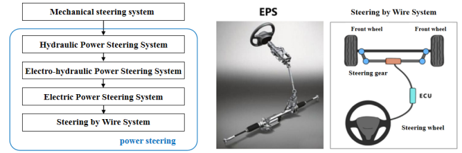
Figure 1. (left) The development of automotive steering system; (right) Concept of steering by wire.
Major automobile manufacturers and suppliers around the world have conducted in-depth research on wire controlled steering systems, and internationally renowned suppliers such as TRW (TRW Automotive Holdings Corp), Delphi, and ZF have manufactured physical prototypes for experimental research. International famous automobile manufacturers such as Mercedes Benz, BMW, General Motors, etc. , exhibited a concept car with a steer-by-wire system. In the late 1960s, Kasselmann in Germanys started to develop steering-by-wire system. In 1990s, Benz initiated its study in front wheel steering study, and applied the steer by wire system on Concept Vehicle ”F400 Carving”. In 2000, BMW applied steering by wire in Concept Vehicle “BMW Z22”, and the steering angle was reduced to 160 degrees. In 2013, Infinity Q50 applied steer-by -wire technology, in which two motors and three inter-monitored ECU were utilized to realize steering. In 2017, Schneider in USA developed steering-by-wire system composed of a “silent steering wheel system” and “on-demand steering system”.At present, the research on the wire-controlled-steering system in China is gradually moving from theory to practice, and some progress has been made [14].
The wire-controlled-steering system is divided into three parts: the steering wheel module, the steering execution module, and central control unit (ECU) [15]. The steering wheel module includes components such as the steering wheel torque, angle sensor, road sensing motor and its reducer [16]; The steering execution module includes components such as the linear displacement sensor, angle sensor, steering motor, and its deceleration mechanism; In addition, the wire-controlled-steering system also includes components such as a steering controller and power supply[17].The steering wheel module (i.e. steering wheel) is used to receive the driver's steering control; The steering wheel torque sensor and angle sensor are used to collect the torque, angle, and speed input by the driver through the steering wheel; The road sensing motor and its reducer provide the driver with road sensing information and output the return torque of the steering wheel.The steering execution module includes various sensors, and the linear displacement sensor is used to collect the linear displacement signal of the steering actuator and convert it into a front wheel angle signal; The angle sensor is used to collect the angle information of the steering wheel; The steering motor and its deceleration mechanism are used to overcome steering resistance and drive the steering system to rotate through the corresponding angle; The gear rack steering gear is used to receive and amplify the output torque of the steering actuator motor, driving the steering wheel to turn.The steering controller consists of multiple controllers. The steering wheel module controller collects relevant signals from the steering wheel module, receives target return torque signals, and sends control signals to the road sensing motor; The steering execution module controller is responsible for collecting relevant signals from the steering execution module, receiving target steering wheel angle signals, and sending control signals to the steering motor [18].The wire-controlled-steering system shares a battery power supply with other electrical equipment in the vehicle. Currently, the mainstream power supply for the vehicle is 12V, and 48V will be the future development trend.
According to the number, arrangement position, and control method of steering motors, the typical layout of wire-controlled steering systems can be divided into five categories, namely single motor-front wheel-steering, dual-motor front-wheel steering, dual-motor independent front-wheel steering, rear-wheel wire-controlled steering, and four-wheel independent steering.The dual motor front wheel steering arrangement has good redundancy and requires less power for a single motor. Infiniti Q50 adopts this arrangement, but the cost of parts in this form increases and the redundancy algorithm is complex.The working schematic of wire-controlled steering is shown in Figure 2.When the driver turns the steering wheel, the angle displacement sensor converts the driver's intention into a digital signal, along with other signals of the vehicle, such as speed signals. Transmitted to the ECU through the bus, the ECU calculates the front wheel angle based on the set algorithm and transmits this signal to the steering motor to complete the steering. In addition, after obtaining the steering resistance information through the steering resistance sensor, the ECU transmits the magnitude of the return torque to the driver for road feel feedback based on the return torque algorithm.
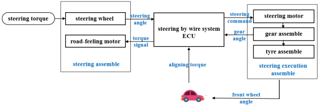
Figure 2. Schematic diagram of steering by wire.
3.Automotive Braking by Wire System
At present, the main research on wire-controlled braking systems at home and abroad are Electronic Hydraulic Braking (EHB) systems, electronic mechanical braking (EMB) systems, and hybrid wire-controlled braking (HBBW) systems, among which the EHB system is the most mature and currently in mass production stage[19-22].Previously, the brake-by-wire system was mainly divided into three types: the first was the Electronic Hydraulic Brake (EHB) system, the second was the Electronic Mechanical Brake (EMB) system, and the third was the Hybrid Brake by Wire (HBBW) system[23-24].
The EHB system is developed on the basis of traditional hydraulic braking systems, using a comprehensive braking system module (motors, pumps, high-pressure accumulators, etc.) to replace the pressure regulation system in traditional braking systems and ABS module that can generate and store brake pressure, and can separately adjust the braking torque of four tires via individual adjustment[25]. The EMB system completely eliminates components such as brake fluid and hydraulic pipelines of traditional brake systems, and is driven by an electric motor. The brake generates braking force, which is truly a wire-controlled braking system. There is no hydraulic drive and control part in the EMB system, and the mechanical connection only exists between the motor and the brake caliper. The driving part transmits energy through wires and signals through data cables[26-27].The mainstream layout of the Hybrid Brake by Wire (HBBW) system is to use an Electronic Hydraulic Brake (EHB) system on the front axle and an Electronic Mechanical Brake (EMB) system on the rear axle;The front axle adopts an EHB system to achieve single wheel braking force adjustment of the front wheel, while relying on the EHB installed on the front axle implement brake failure backup to meet safety and reliability requirements; The rear axle adopts an EMB system, which can reduce the length of the brake pipeline and eliminate the uncertainty caused by the excessively long pipeline during pressure control; on the other hand, it can make the electronic parking brake (EPB) more convenient and fast[28].The automotive Electronic Hydraulic Braking system (EHB) is mainly composed of a hydraulic control module, brake pedal module, control unit HCU, brake, various sensors, etc. [29]. The working process of the EHB system mainly involves controlling the pressure supply unit and the high-speed on-off valve, generating and storing brake pressure, and adjusting the brake torque of the four tires separately[30].The electronic mechanical braking system (EMB) for automobiles mainly consists of wheel brake modules, central electronic control units (ECU), brake pedal modules, communication networks, power supplies, and other components. The EMB system replaces hydraulic components with electronic components, which is an electro-mechanical integrated system. The system controls the current level of the brake motor through an electronic control unit, and clamps the friction discs from both sides through the brake clamps to achieve wheel braking.The key technologies that limit the mass production and application of EMB systems include redundant design and fault-tolerant control, clamping force control technology, reliability of brushless motors in complex environments, and innovative and miniaturized gearing mechanisms. Based on the vehicle dynamic control system of the EMB system, which is distinct from closed-loop control based on hydraulics, the development of an entirely new dynamic model and vehicle coordination control algorithm is necessary.Figure 3 presents the system architectures of EHB, EMB, and HBBW.
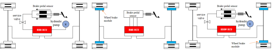
Figure 3. EHB, EMB and HBBW system.
There are already some mature algorithms such as PID, SMC, MPC, etc., which have successfully helped the integrated line control system achieve power cylinder pressure control. Todeschini of the Polytechnic University of Milan and others proposed a position pressure hybrid switching power cylinder control strategy for the self-designed brake-by-wire system. In the position control mode, they quickly controlled the motor to rotate fully to overcome the brake system's idle stroke, and in the pressure control mode, they used variable parameter PID. The closed-loop control accurately adjusts the pressure of the power cylinder, effectively improving the pressure regulation rate of the active braking system of this configuration [31-32].
4.Automotive Driving by Wire System
For internal combustion engine vehicles, the wire-controlled throttle system has replaced the traditional throttle system, and more than 99% of vehicle models on the market are equipped with a fuel-control door system. For new energy vehicles, the mainstream driving solutions currently include centralized motor drive and step-by-step motor drive, and the centralized motor drive solution has received a large number of applications, but is developing towards distributed motor drive represented by wheel edge and hub motors[33-36].
The wire-controlled throttle system is composed of the throttle pedal, pedal displacement sensor, electronic control unit, data bus, servo motor, and throttle actuator. The drive-by-wire system consists of the electronic control unit (ECU), power converter, drive motor, mechanical transmission system, drive wheel, etc.. The wire-controlled drive system structure for new energy vehicles is mainly divided into three types: centralized drive, central transmission drive, and distributed drive. At present, electric drive bridge technology, wheel edge deceleration drive, and hub motor direct drive technology are mainstream structures[37-39].The wire-controlled throttle is controlled by a cable or wire harness to control the throttle opening. On the surface, it replaces the traditional throttle cable with a cable, but in essence, it is not just a simple change in the connection method, but can achieve automatic control of the entire vehicle's power output[40-42].
The driving control of pure electric vehicles is achieved through a control strategy program embedded in the vehicle controller. Based on the input signals of each sensor, the vehicle's operating conditions are determined and the target torque of the driving motor under each operating condition is determined[43]. Then, the target value is sent to the motor controller (MCU) through CAN bus, and the motor controller controls the motor according to the received commands to ensure normal driving of the vehicle[44].The hub motor drive system can be flexibly placed in the wheels of various electric vehicles, directly driving the hub to rotate. Compared with traditional centralized driving methods such as internal combustion engines and single motors, its technical advantages and characteristics in power configuration, transmission structure, handling performance, energy utilization, etc., are extremely obvious[45].
Hub motors are mainly divided into two types: outer rotor motors and inner rotor motors, with differences mainly reflected in the presence or absence of a reduction structure. The inner rotor hub motor and wheel edge motor converge in transmission structure, with the main difference being that the inner rotor motor is integrated with the hub, while the wheel edge motor is placed on the wheel edge[46].The schematic diagram of the hub motor drive device is shown in Figure 4. Overall, the application of wheel hub motors has the advantages of high integration, flexible driving, and being in line with the development of intelligent vehicles and platform generalization applications[47].
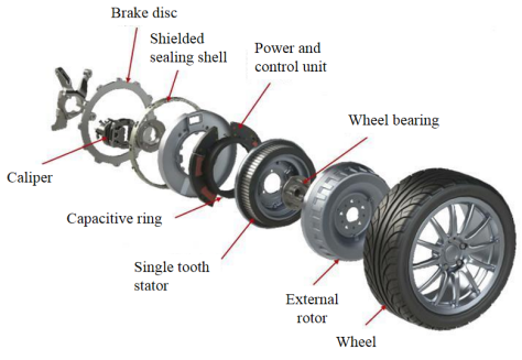
Figure 4. Schematic diagram of hub motor drive
5.Automotive Suspension by Wire System
During vehicle driving and riding, handling and comfort are two important evaluation indicators, which are difficult to balance. Control by wire suspension is the process of automatically adjusting the height, stiffness, and damping of the suspension according to the actual road conditions to achieve precise control of the driving attitude[48].
According to the actuator, from the perspective of technological maturity and equipment rate, air springs and CDC-type wire-controlled shock absorbers are the most common. The MRC shock absorber has good shock absorption effect and fast response speed[49-50]. There will be good development space after the price drops in the later stage. Due to its strong substitutability, the necessity of equipping the wire controlled anti-roll bar is relatively low.Figure 5 illustrates the basic structure of an air suspension system.According to the degree of additional external force intervention, an automotive suspension system can be classified as follows: passive, semi-active and full active. The cost of semi-active control is lower than that of full active control, its performance is close to that of a full active suspension system, and it has reliable fault state adaptability, which is the mainstream of the current market[51]. With the improvement of the level of automatic driving and the access of various sensors, the popularity of full active suspension will increase day by day[52].
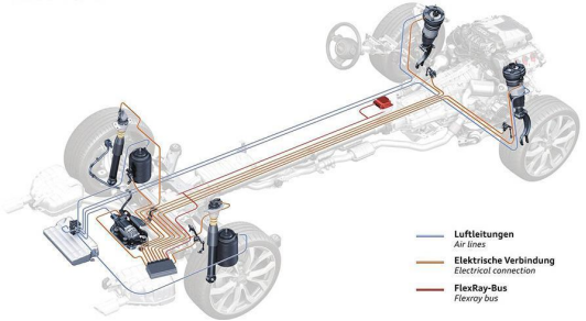
Figure 5. Basic structure of air suspension
The wire-controlled suspension system usually has two sets of information collection and control systems in parallel, and solving the control coupling of different systems under different road conditions is its control difficulty; The current mainstream control scheme is that the wire-controlled spring is generally adjusted in steady-state, and the wire-controlled vibration reduction is generally adjusted in real-time.The wire-controlled suspension control system is a closed-loop adaptive control system that does not have an optimal solution. The core parameters need to be continuously calibrated during the calibration process based on simulation models and actual vehicle test results.PID (proportional, integral, differential) control is the most widely used and mature control method in the control field, which is widely used in the active and semi active suspension of vehicles[53]. The adjustment of proportion (single adjustment amplitude), integration (elimination of static error), and differentiation (reflecting the trend of input signal change) parameters can be achieved through simulation testing and actual vehicle testing
References
- 1.Tang, P.; Zhao, H.J.; Xu, Z. Current Situation and Trend of Wire-Controlled Chassis Control Technology Development. In Proceedings of SPIE—The International Conference on Optical Engineering, Nanjing, China, 24–27 November 2022; p. 12309.
- Fu, Y.; Zhang, L.; Wei, C.; Tang, P. Research and analysis of steering-by-wire system stability. Phys. Conf. Ser. 2021, 2121, 012028.
- Hu, C., Pan, G., Kong, L., & Yu, J. Research of Brake by Wire System. Journal of Physics. 2023, 1, 2479.
- Jian, L. Research status and development prospect of electric vehicles based on hub motor. In Proceedings of the China International Conference on Electricity Distribution. 2018, 17–19, 126–129.
- Zhang, Y.; Lu, G. Research on Control Method of Four-Wheel-Independent-Driving System Based on X-by-Wire Chassis. Lect. Notes Electr. Eng. 2022, 769, 603–626.
- Wang, Y., Yang, J. J. An automotive EHPS software reliability and testing. Proceedings - Annual Reliability and Maintainability Symposium. 2020, doi: 10.1109/RAMS48030.2020.9153725, 1-6.
- Irmer, M.; Degen, R.; Nubgen,; A.Thomas, K.; Henrichfreise, H.; Ruschitzka, M. Development and Analysis of a Detail Model for Steer-by-Wire Systems. IEEE Access. 2023, 11, 7229–7236.
- Orizco, A.R. Evaluation of an Active Steering System; KTH Royal Institute of Technology,Sweden, 2004.
- Badawy, A.; Zuraski, J.; Bolourchi, F.; Chandy, A. Modeling and Analysis of an Electric Power Steering System; SAE International, United States Paper No.1999-01-0399; 1999.
- Mortazavizadeh, S.A.; Ghaderi, A.; Ebrahimi, M.; Hajian, M. Recent Developments in the Vehicle Steer-by-Wire System. IEEE Trans. Transp. Electrif. 2020, 6, 1226–1235.
- Isah, A.; Mohammed, A.; Hamza, A. Electric Power-Assisted Steering: A Review. In Proceedings of the 2019 2nd International Conference of the IEEE Nigeria Computer Chapter. 2019, NigeriaComputConf 2019, Zaria, Nigeria, 14–17.
- Indrawanto Ayatullah, T.; Prayoga, R.A. On the Design of Electric Power Steering Control Unit. In Proceedings of the 2018 5th International Conference on Electric Vehicular Technology. 2018, 30-31, 210–213.
- Zhang, Z.; Ge, Y.; Li, C.; Xu, P. Research on EPS Control Strategy Based on BAS Algorithm. In 2022 41st Chinese Control Conference, CCC;IEEE Computer Society. 2022, IEEE Computer Society,Wuhu, China, 2022, 5408–5413.
- Simionescu, P.A.; Hoeltgebaum, T.; Martins, D. On the Evolution of Automotive Steering Mechanisms. Mech. Mach. Sci. 2022, 118, 116–128.
- Hu, A. Development of the automobile steering system. Appl. Mech. Mater. 2011, 42, 272–275.
- Cheon, D.; Nam, K.; Oh, S. Design and Robust Control of a Precise Torque Controllable Steering Module for Steer-by-Wire Systems. IEEE Trans. Ind. Electron. 2022, 69, 13245–13254.
- Cong, Z.; Jian, X.; Iqbal, M.N. Review on automobile steering-by-wire system development. Appl. Mech. Mater. 2012, 130–134, 2194–2197.
- Salih, S.Y. Intelligent Performance, Architecture Analysis, Functional Safety Metrics of Automated Steering Systems for Autonomous Vehicles. In ProQuest Dissertations and Theses Global; ProQuest LLC: Ann Arbor, MI, USA, 2022.
- Wang, X.; Xie, X.; Wu, X.; Yu, T. Precise position tracking control based on adaptive neuron PID algorithm for automatic clutch driven by DC motor. IEEE: Toulouse, France. 2008, 3–5 , 1–4.
- Kim, J.; Choi, S.B. Design and modeling of a clutch actuator system with self-energizing mechanism. IEEE/ASME Trans. Mechatron. 2011, 16, 953–966.
- Line, C.; Manzie, C.; Good, M.C. Electromechanical brake modeling and control. IEEE Trans. Control. Syst. Technol. 2008, 16, 446–457.
- Liu, Y.; Li, B. Research on EHB System Algorithm and Controller Implementation of Energy Vehicle. Research on EHB System Algorithm and Controller Implementation of Energy Vehicle.
- Xu, Z.; Gao, G. Research on EMB control strategy considering braking gap. In Proceedings of SPIE—The International Conference on Optical Engineering. 2022, 24–27, 12329.
- Chen, Z.; Wu, J.; Zhao, J.; He, R.; Qi, S. Control Strategy for Accurate Adjustment of Braking Force in Hybrid Brake by Wire System. Qiche Gongcheng/Automot. Eng. 2018, 40, 457–464.
- Chen, Y.-C.; Tu, C.-H.; Lin, C.-L. Integrated electromagnetic braking/driving control of electric vehicles using fuzzy inference. 38.IET Electr. Power Appl. 2019, 13, 1014–1021.
- Todeschini, F.; Corno, M.; Panzani, G.; Savaresi, S.M. Adaptive position–pressure control of a brake by wire actuator for sport motorcycles. Eur. J. Control. 2014, 20, 79–86.
- Todeschini, F.; Formentin, S.; Panzani, G.; Corno, M.; Savaresi, S.M.; Zaccarian, L. Nonlinear pressure control for bbw systems via dead-zone and antiwindup compensation. IEEE Trans. Control. Syst. Technol. 2016, 24, 1419–1431.
- Tamilselvan, S., Prakash, N., Sathyamurthy, R. (2023). Review of Comprehensive Survey on Recent Trends in Parking Brake System. In: Sethuraman, B., Jain, P., Gupta, M. (eds) Recent Advances in Mechanical Engineering. STAAAR 2022. Lecture Notes in Mechanical Engineering. Springer, Singapore.
- Jiang, J.N.; Wang, S.H.; Sun, W.B. Simulation and optimization of automatic transmission hydraulic control module. In Proceedings of the 2017 2nd International Conference on Robotics and Automation Engineering, ICRAE 2017, Shanghai, China, 29–31 December 2017; pp. 243–247.
- Chen, L.; Chi, H.; Feng, Y.; Zhang, C. Research on New Automotive Electronic Hydraulic Brake System. J. Phys. Conf. Ser. 2020, 1605, 012020.
- Todeschini, F.; Corno, M.; Panzani, G.; Fiorenti, S.; Savaresi, S.M. Adaptive cascade control of a brake-by-wire actuator for sport motorcycles. IEEE/ASME Trans. Mechatron. 2015, 20, 1310–1319.
- Yong, J.; Gao, F.; Ding, N.; He, Y. Design and validation of an electro-hydraulic brake system using hardware-in-the-loop real-time simulation. Int. J. Automot. Technol. 2017, 18, 603–612.
- Vo-Duy, T.; Ta, M.C.; Nguyễn, B.H.; Trovão, J.P.F. Experimental Platform for Evaluation of On-Board Real-Time Motion Controllers for Electric Vehicles. Energies. 2020, 13, 6448.
- Wenwei, W.; Wei, Z.; Hanyu, Z.; Wanke, C. Yaw stability control through independent driving torque control of mid and rear wheels of an articulated bus. Proc. Inst. Mech. Eng. Part D-J. Automob. Eng. 2020, 234, 2947–2960.
- Guo, L.; Xu, H.; Zou, J.; Jie, H.; Zheng, G. A state observation and torque compensation-based acceleration slip regulation control approach for a four-wheel independent drive electric vehicle under slope driving. 54.Proc. Inst. Mech. Eng. Part D-J. Automob. Eng. . 2020, 234, 2728–2743.
- Aloeyi, E.F.; Ali, N.; Wang, Q. A Review of In-Wheel Motors for Electric Vehicle Propulsion. In Proceedings of the 2022 IEEE Transportation Electrification Conference and Expo. 2022, https://doi.org/10.1109/ITECAsia-Pacific56316.2022.9941742, 28–31.
- Mao, X.; Wang, X.; Zhang, J.C.; Chen, K.; Zhao, J.; Zhang, Y. Design of Electric Orchard Vehicle Four-Wheel Steering Control System. Adv. Mater. Res. 2013, 753, 1966–1969.
- Goyal, A.; Thakur, A. An Overview of Drive by Wire Technology for Automobiles. In Proceedings of the 2019 International Conference on Automation, Computational and Technology Management, ICACTM 2019, London, UK, 24–26 April 2019; pp. 108–110.
- Yu, L.; Yuan, S. Qual. Eng. Integrated control performance of drive-by-wire independent drive electric vehicle. Int. J. Metrol. 2019, 10, 16.
- Song, S.; Sun, C.; Zheng, C.; Song, G. J. Research on pure electric vehicle driving motor. Phys. Conf. Ser. 2020, 1650, 022108.
- Muton, N.; Nakauo, Y. Dynamics of Front-and-Rear-Wheel-Independent- Drive-Type Electric Vehicles at the Time of Failure. IEEE Trans. Ind. Electron. 2012, 59, 1488–1499.
- Chen, W.; Liang, X.; Wang, Q.; Zhao, L.; Wang, X. Extension coordinated control of four wheel independent drive electric vehicles by AFS and DYC. Control. Eng. Pract. 2020, 101, 104504.
- Leng, B.; Xiong, L.; Yu, Z.; Sun, K.; Liu, M. Robust Variable Structure Anti-Slip Control Method of a Distributed Drive Electric Vehicle. IEEE Access. 2020, 8, 162196–162208.
- Xin, X.; Lu, X.; Yuye, H.; Guowen, T.; Zhuoping, Y. Vehicle Stability Control Based on Driver’s Emergency Alignment Intention Recognition. Int. J. Automot. Technol. 2017, 18, 993–1006.
- Ren, L.; Zhou, J.; Shen, G. The active steering control of the independent wheelset with the hub motors. Zhongguo Tiedao Kexue/China Railw. Sci. 2010, 31, 77–83.
- Cheng, X.; Chen, T.; Li, J.; Wang, J. Coordinated Control Method for Lateral Stability and Differential Power-Assisted Steering of In-Wheel Motor Drive Electric Vehicles. World Electr. Veh. J. 2023, 14, 200.
- Yao, X.; Zhou, M.; Li, L.; Zhang, X.; Zhong, X.; Zeng, L.; Guo, C. Structural Design of Hub Motor Based on Bidirectional Excitation. J. Phys. Conf. Ser. 2023, 2468, 012172.
- Liu, Z.-S. Optimum design and control research of direct drive hub motor. Smart Innov. Syst. Technol. 2018, 82, 244–254.
- Yao, Q.; Li, Q.; Du, Q.; Chen, S.; Wang, X.; Zhan, W.; Yin, S. Research on Trailing Arm Suspension System of Full X-by-Wire Control Chassis Based on Data Drive. Lixue Xuebao/Chin. J. Theor. Appl. Mech. 2022, 54, 1880–1895.
- Yang, P.; Ge, Y.; Liu, H.; Zeng, X.; Li, C. Joint Control of Semi-active Suspension Based on CDC Shock Absorber. In Proceedings of the 41stChinese Control Conference, CCC, Anhui, China. 2022, 25–27, 5396–5401.
- Kordonsky, W.I. J. Magnetorheological effect as a base of new devices and technologies. Magn. Magn. Mater. 1993, 122, 395–398.
- Tang, T.; Sha, S.; Pan, C.; Li, H. Sliding Mode Control of Vehicle Semi-active Suspension System Based on Magnetorheological Damper. J. Phys. Conf. Ser. 2023, 2459, 012085.
- Kumar, S.; Medhavi, A.; Kumar, R. Modeling of an active suspension system with different suspension parameters for full vehicle. Indian J. Eng. Mater. Sci. 2021, 28, 55–63.

