Automotive chassis control technology plays a crucial role in ensuring the stability, performance, and safety of vehicles. This paper reviews and discusses automotive steering/braking/driving/suspension systems from perspectives of system composition, the state of the art, and key technologies. Detailed analysis is conducted on critical techniques related to system fault tolerance, road feel feedback, brake force distribution strategy, electric motors, and motor controllers.The development and application of automotive chassis control technology is in line with the goals and objectives for the advancement of the automotive industry in terms of innovation, safety, and environmental sustainability.汽车底盘控制技术在确保车辆的稳定性、性能和安全性方面发挥着至关重要的作用。
- steering by wire
- braking by wire
- driving by wire
- suspension by wire
1.Introduction
1. 引言
Automotive chassis control technology plays a crucial role in ensuring the stability, performance, and safety of vehicles. It encompasses a range of systems and components that work together to manage and optimize various aspects of a vehicle's dynamics, including suspension, steering, braking, traction, and stability control. These systems not only enhance the driving experience but also contribute to preventing accidents and improving overall vehicle safety.With the advancement of autonomous driving technology, the implementation of autonomous driving functions relies on the coordinated cooperation of the perception layer, decision layer, and execution layer, thus posing higher demands on vehicle chassis that integrate all control functions in the execution layer. The wire-controlled chassis upgrades mechanical transmission control to wire-controlled, which meets the real-time, safety redundancy, high-performance, and intelligent requirements of autonomous driving technology in the chassis level for electrical signal transmission.
Throughout history, chassis control technology has significantly evolved. Initially, simple mechanical systems were used to provide basic suspension and steering functions. However, with advancements in technology, the sophistication and capabilities of these systems have increased exponentially. Today, automotive manufacturers employ diverse types of suspension systems, such as independent and active suspensions, to deliver superior ride comfort and handling performance[1].The steering system is another pivotal component of chassis control technology. Traditional steering mechanisms, such as rack and pinion systems, have been replaced by electric power steering (EPS) in modern vehicles. EPS offers improved precision, control, and fuel efficiency, making it an integral part of contemporary chassis control systems[2]. Additionally, steer-by-wire technology is gaining attention, enabling electronic control of steering, further revolutionizing the driving experience.
One cannot overlook the significance of braking systems within the realm of chassis control. The braking system ensures the vehicle's ability to decelerate and stop safely. Traditionally, hydraulic braking systems have been used, but advancements such as anti-lock braking systems (ABS) and regenerative braking have been introduced. ABS prevents wheel lock-up during emergency braking situations, enhancing control and stability. Regenerative braking, commonly found in electric and hybrid vehicles, converts kinetic energy into electrical energy, increasing overall efficiency[3]Traction and stability control systems play a pivotal role in maintaining vehicle stability and preventing accidents. Traction control systems manage wheel slip during acceleration, ensuring maximum traction even on slippery surfaces. Electronic Stability Control (ESC) combines various sensors and control mechanisms to automatically detect and correct lateral skidding or loss of control[4]. It is an essential safety feature in modern vehicles, significantly reducing the risk of rollovers.Automotive chassis control technology encompasses various systems and components that work together to improve vehicle performance, stability, and safety. From suspension and steering to braking and traction control, each component plays a crucial role in ensuring a smooth and safe driving experience[5]. With advancements in technology, the integration and communication between these components have become more sophisticated, promising even more exciting developments in the future.
However, wire-controlled chassis systems still face some challenges. For example, the cost of hardware redundancy design and software redundancy design is relatively high, requiring a balance between reliability, cost, and performance. In addition, the safety and reliability of wire-controlled steering systems still need to be improved. Since wire-controlled braking systems rely on controllers to achieve system control, factors such as controller reliability, anti-interference, fault-tolerance, and real-time response between multiple control systems communication all have the potential to impact brake control. However, with the continuous development of technology, future wire-controlled chassis technology is expected to become more mature and reliable, making greater contributions to the development of the automotive industry.
2.Automotive
2. 汽车线控转向系统
2.1. 最新技术
如图1所示,汽车转向系统经历了机械转向系统、液压助力转向(HPS)系统、电液助力转向(EHPS)系统、电动助力转向(EPS)系统和线控转向(SBW)系统[7,8]。与EPS相比,线控转向系统消除了方向盘和方向盘之间的机械连接[9,10,11,12,13,14]。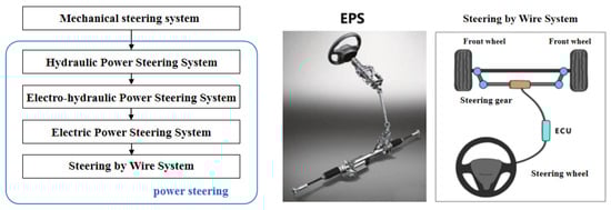
As shown in Figure 1, the automotive steering system has gone through several stages including a mechanical steering system, hydraulic-power-assisted steering (HPS) system, electro-hydraulic-power-assisted steering (EHPS) system, electric-power- assisted steering (EPS) system, and a steer-by-wire (SBW) system [6,7]. The wire- controlled steering system eliminates the mechanical connection between the steering wheel and the steering wheel compared to EPS [8-13].
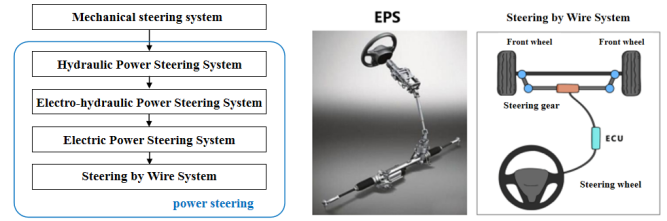
Figure 1. (left) The development of automotive steering system; (right) Concept of steering by wire.
Major automobile manufacturers and suppliers around the world have conducted in-depth research on wire controlled steering systems, and internationally renowned suppliers such as TRW (TRW Automotive Holdings Corp), Delphi, and ZF have manufactured physical prototypes for experimental research. International famous automobile manufacturers such as Mercedes Benz, BMW, General Motors, etc. , exhibited a concept car with a steer-by-wire system. In the late 1960s, Kasselmann in Germanys started to develop steering-by-wire system. In 1990s, Benz initiated its study in front wheel steering study, and applied the steer by wire system on Concept Vehicle ”F400 Carving”. In 2000, BMW applied steering by wire in Concept Vehicle “BMW Z22”, and the steering angle was reduced to 160 degrees. In 2013, Infinity Q50 applied steer-by -wire technology, in which two motors and three inter-monitored ECU were utilized to realize steering. In 2017, Schneider in USA developed steering-by-wire system composed of a “silent steering wheel system” and “on-demand steering system”.At present, the research on the wire-controlled-steering system in China is gradually moving from theory to practice, and some progress has been made [14].
The wire-controlled-steering system is divided into three parts: the steering wheel module, the steering execution module, and central control unit (ECU) [15]. The steering wheel module includes components such as the steering wheel torque, angle sensor, road sensing motor and its reducer [16]; The steering execution module includes components such as the linear displacement sensor, angle sensor, steering motor, and its deceleration mechanism; In addition, the wire-controlled-steering system also includes components such as a steering controller and power supply[17].The steering wheel module (i.e. steering wheel) is used to receive the driver's steering control; The steering wheel torque sensor and angle sensor are used to collect the torque, angle, and speed input by the driver through the steering wheel; The road sensing motor and its reducer provide the driver with road sensing information and output the return torque of the steering wheel.The steering execution module includes various sensors, and the linear displacement sensor is used to collect the linear displacement signal of the steering actuator and convert it into a front wheel angle signal; The angle sensor is used to collect the angle information of the steering wheel; The steering motor and its deceleration mechanism are used to overcome steering resistance and drive the steering system to rotate through the corresponding angle; The gear rack steering gear is used to receive and amplify the output torque of the steering actuator motor, driving the steering wheel to turn.The steering controller consists of multiple controllers. The steering wheel module controller collects relevant signals from the steering wheel module, receives target return torque signals, and sends control signals to the road sensing motor; The steering execution module controller is responsible for collecting relevant signals from the steering execution module, receiving target steering wheel angle signals, and sending control signals to the steering motor [18].The wire-controlled-steering system shares a battery power supply with other electrical equipment in the vehicle. Currently, the mainstream power supply for the vehicle is 12V, and 48V will be the future development trend.
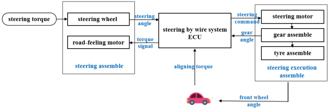
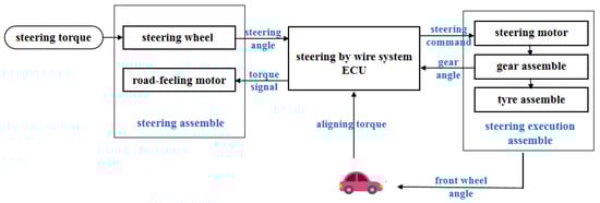
According to the number, arrangement position, and control method of steering motors, the typical layout of wire-controlled steering systems can be divided into five categories, namely single motor-front wheel-steering, dual-motor front-wheel steering, dual-motor independent front-wheel steering, rear-wheel wire-controlled steering, and four-wheel independent steering.The dual motor front wheel steering arrangement has good redundancy and requires less power for a single motor. Infiniti Q50 adopts this arrangement, but the cost of parts in this form increases and the redundancy algorithm is complex.The working schematic of wire-controlled steering is shown in Figure 2.When the driver turns the steering wheel, the angle displacement sensor converts the driver's intention into a digital signal, along with other signals of the vehicle, such as speed signals. Transmitted to the ECU through the bus, the ECU calculates the front wheel angle based on the set algorithm and transmits this signal to the steering motor to complete the steering. In addition, after obtaining the steering resistance information through the steering resistance sensor, the ECU transmits the magnitude of the return torque to the driver for road feel feedback based on the return torque algorithm.
Figure
2.2. 关键技术
- (1)
-
容错
- (2)
-
路感反馈
3. 汽车线控制动系统
3.1. 最新技术
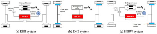
目前,国内外对线控制动系统的主要研究有电子液力制动(EHB)系统、电子机械制动(EMB)系统和混合线控制动(HBBW)系统,其中EHB系统最为成熟,目前处于量产阶段[32,33,34,35]。 此前,线控制动系统主要分为三种类型:第一种是电子液压制动(EHB)系统,第二种是电子机械制动(EMB)系统,第三种是混合线控制动(HBBW)系统[36\u201237]。 EHB系统是在传统液压制动系统的基础上发展起来的,采用综合制动系统模块(电机、泵、高压蓄能器等)代替传统制动系统中的压力调节系统和ABS模块,可以产生和储存制动压力,通过单独调节分别调节四个轮胎的制动力矩[38].EMB系统完全省去了传统制动系统的制动液和液压管路等部件,由电动机驱动。制动器产生制动力,这是真正的线控制动系统。EMB系统中没有液压驱动和控制部分,仅存在于电机和制动钳之间。驱动部分通过导线传输能量,通过数据线传输信号[39\u201240]。 前桥采用EHB系统,实现前轮单轮制动力调节,同时依靠安装在前桥上的EHB机具制动故障备份,满足安全可靠性要求;后桥采用EMB系统,可减少制动管路长度,消除压力控制时管路过长带来的不确定性;另一方面,它可以使电子驻车制动器(EPB)更加方便快捷[41]。 汽车电子液压制动系统(EHB)主要由液压控制模块、制动踏板模块、控制单元HCU、制动器、各种传感器等组成[42]。EHB系统的工作过程主要包括控制供压单元和高速开关阀,产生和储存制动压力,分别调节四个轮胎的制动扭矩[43]。 汽车电子机械制动系统(EMB)主要由车轮制动模块、中央电子控制单元(ECU)、制动踏板模块、通信网络、电源等部件组成。EMB系统用电子元件代替液压元件,是一个机电一体化系统。该系统通过电子控制单元控制制动电机的电流水平,并通过制动夹从两侧夹紧摩擦盘,实现车轮制动。限制EMB系统量产和应用的关键技术包括冗余设计和容错控制、夹紧力控制技术、复杂环境下无刷电机的可靠性以及创新和小型化的齿轮机构。基于EMB系统的车辆动态控制系统,有别于基于液压的闭环控制,需要开发一种全新的动态模型和车辆协调控制算法。图
Schematic diagram of steering by wire.
3.Automotive Braking by Wire System
At present, the main research on wire-controlled braking systems at home and abroad are Electronic Hydraulic Braking (EHB) systems, electronic mechanical braking (EMB) systems, and hybrid wire-controlled braking (HBBW) systems, among which the EHB system is the most mature and currently in mass production stage[19-22].Previously, the brake-by-wire system was mainly divided into three types: the first was the Electronic Hydraulic Brake (EHB) system, the second was the Electronic Mechanical Brake (EMB) system, and the third was the Hybrid Brake by Wire (HBBW) system[23-24].
The EHB system is developed on the basis of traditional hydraulic braking systems, using a comprehensive braking system module (motors, pumps, high-pressure accumulators, etc.) to replace the pressure regulation system in traditional braking systems and ABS module that can generate and store brake pressure, and can separately adjust the braking torque of four tires via individual adjustment[25]. The EMB system completely eliminates components such as brake fluid and hydraulic pipelines of traditional brake systems, and is driven by an electric motor. The brake generates braking force, which is truly a wire-controlled braking system. There is no hydraulic drive and control part in the EMB system, and the mechanical connection only exists between the motor and the brake caliper. The driving part transmits energy through wires and signals through data cables[26-27].The mainstream layout of the Hybrid Brake by Wire (HBBW) system is to use an Electronic Hydraulic Brake (EHB) system on the front axle and an Electronic Mechanical Brake (EMB) system on the rear axle;The front axle adopts an EHB system to achieve single wheel braking force adjustment of the front wheel, while relying on the EHB installed on the front axle implement brake failure backup to meet safety and reliability requirements; The rear axle adopts an EMB system, which can reduce the length of the brake pipeline and eliminate the uncertainty caused by the excessively long pipeline during pressure control; on the other hand, it can make the electronic parking brake (EPB) more convenient and fast[28].The automotive Electronic Hydraulic Braking system (EHB) is mainly composed of a hydraulic control module, brake pedal module, control unit HCU, brake, various sensors, etc. [29]. The working process of the EHB system mainly involves controlling the pressure supply unit and the high-speed on-off valve, generating and storing brake pressure, and adjusting the brake torque of the four tires separately[30].The electronic mechanical braking system (EMB) for automobiles mainly consists of wheel brake modules, central electronic control units (ECU), brake pedal modules, communication networks, power supplies, and other components. The EMB system replaces hydraulic components with electronic components, which is an electro-mechanical integrated system. The system controls the current level of the brake motor through an electronic control unit, and clamps the friction discs from both sides through the brake clamps to achieve wheel braking.The key technologies that limit the mass production and application of EMB systems include redundant design and fault-tolerant control, clamping force control technology, reliability of brushless motors in complex environments, and innovative and miniaturized gearing mechanisms. Based on the vehicle dynamic control system of the EMB system, which is distinct from closed-loop control based on hydraulics, the development of an entirely new dynamic model and vehicle coordination control algorithm is necessary.Figure 3 presents the system architectures of EHB, EMB, and HBBW.
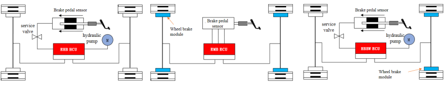
Figure
3.2. 关键技术
- (1)
-
制动力的最优分配策略制动力分配的目的是根据驾驶员踩下制动踏板瞬间的车辆载荷、实际路况和运行工况来计算四轮制动器的制动力,以保证车辆的安全稳定,同时获得最短的制动距离[46\u201247]。传统液压制动系统中踏板位移、踏板力、制动压力之间的关系可以从EMB系统中踏板力与制动减速度的关系中推断出来,并建立关系曲线。由于轮胎和路面粘附系数等因素,车轮的最大地面制动力不应超过粘附力[48]。当局部制动力超过粘附力时,车轮可能会发生抱死打滑,并可能出现前轮抱死或后轮抱死等现象。
- (2)
-
系统安全和容错
4. 汽车线控驱动系统
4.1. 最新技术
对于内燃机汽车来说,线控节气门系统已经取代了传统的节气门系统,市场上99%以上的车型都配备了油控门系统。对于新能源汽车,目前主流的驱动方案包括集中式电机驱动和步进式电机驱动,集中式电机驱动解决方案已获得大量应用,但正向以轮缘和轮毂电机为代表的分布式电机驱动方向发展[52,53,54,55]。 线控节气门系统由节气门踏板、踏板位移传感器、电控单元、数据总线、伺服电机、节气门执行器组成。线控驱动系统由电子控制单元(ECU)、电源变换器、驱动电机、机械传动系统、驱动轮等组成[56]。新能源汽车的线控驱动系统结构主要分为集中驱动、中央传动驱动、分布式驱动三种。目前,电驱动桥技术、轮缘减速驱动、轮毂电机直驱技术是主流结构[57,58,59]。 线控节气门由电缆或线束控制,以控制节气门开度。从表面上看,它用一根电缆代替了传统的油门电缆,但实质上,它不仅仅是连接方式的简单改变,而是可以实现对整车功率输出的自动控制[60,61,62]。 纯电动汽车的驾驶控制是通过嵌入在车辆控制器中的控制策略程序来实现的。根据每个传感器的输入信号,确定车辆的运行工况,并确定驱动电机在每种工况下的目标转矩[63]。然后,通过CAN总线将目标值发送到电机控制器(MCU),电机控制器根据接收到的命令控制电机,以保证车辆的正常行驶[64]。4.2. Key Technologies
- (1)
-
Efficiency improvement of permanent magnet synchronous motor
- (2)
-
Hub Motor Technology
- 3)
-
Motor controller
5. Automotive Suspension by Wire System
5.1. The State of the Art
During vehicle driving and riding, handling and comfort are two important evaluation indicators, which are difficult to balance. Control by wire suspension is the process of automatically adjusting the height, stiffness, and damping of the suspension according to the actual road conditions to achieve precise control of the driving attitude [76]. 根据执行器,从技术成熟度和设备率来看,空气弹簧和CDC型线控减震器最为常见。MRC减震器减震效果好,响应速度快[77\u201278]。后期降价后会有不错的发展空间。由于其强大的可替代性,配备线控防倾杆的必要性相对较低。图
EHB, EMB and HBBW system.
There are already some mature algorithms such as PID, SMC, MPC, etc., which have successfully helped the integrated line control system achieve power cylinder pressure control. Todeschini of the Polytechnic University of Milan and others proposed a position pressure hybrid switching power cylinder control strategy for the self-designed brake-by-wire system. In the position control mode, they quickly controlled the motor to rotate fully to overcome the brake system's idle stroke, and in the pressure control mode, they used variable parameter PID. The closed-loop control accurately adjusts the pressure of the power cylinder, effectively improving the pressure regulation rate of the active braking system of this configuration [31-32].
4.Automotive Driving by Wire System
For internal combustion engine vehicles, the wire-controlled throttle system has replaced the traditional throttle system, and more than 99% of vehicle models on the market are equipped with a fuel-control door system. For new energy vehicles, the mainstream driving solutions currently include centralized motor drive and step-by-step motor drive, and the centralized motor drive solution has received a large number of applications, but is developing towards distributed motor drive represented by wheel edge and hub motors[33-36].
The wire-controlled throttle system is composed of the throttle pedal, pedal displacement sensor, electronic control unit, data bus, servo motor, and throttle actuator. The drive-by-wire system consists of the electronic control unit (ECU), power converter, drive motor, mechanical transmission system, drive wheel, etc.. The wire-controlled drive system structure for new energy vehicles is mainly divided into three types: centralized drive, central transmission drive, and distributed drive. At present, electric drive bridge technology, wheel edge deceleration drive, and hub motor direct drive technology are mainstream structures[37-39].The wire-controlled throttle is controlled by a cable or wire harness to control the throttle opening. On the surface, it replaces the traditional throttle cable with a cable, but in essence, it is not just a simple change in the connection method, but can achieve automatic control of the entire vehicle's power output[40-42].
The driving control of pure electric vehicles is achieved through a control strategy program embedded in the vehicle controller. Based on the input signals of each sensor, the vehicle's operating conditions are determined and the target torque of the driving motor under each operating condition is determined[43]. Then, the target value is sent to the motor controller (MCU) through CAN bus, and the motor controller controls the motor according to the received commands to ensure normal driving of the vehicle[44].The hub motor drive system can be flexibly placed in the wheels of various electric vehicles, directly driving the hub to rotate. Compared with traditional centralized driving methods such as internal combustion engines and single motors, its technical advantages and characteristics in power configuration, transmission structure, handling performance, energy utilization, etc., are extremely obvious[45].
Hub motors are mainly divided into two types: outer rotor motors and inner rotor motors, with differences mainly reflected in the presence or absence of a reduction structure. The inner rotor hub motor and wheel edge motor converge in transmission structure, with the main difference being that the inner rotor motor is integrated with the hub, while the wheel edge motor is placed on the wheel edge[46].The schematic diagram of the hub motor drive device is shown in Figure 4. Overall, the application of wheel hub motors has the advantages of high integration, flexible driving, and being in line with the development of intelligent vehicles and platform generalization applications[47].
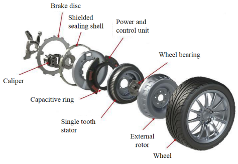
Figure 4. Schematic diagram of hub motor drive
5.Automotive Suspension by Wire System
During vehicle driving and riding, handling and comfort are two important evaluation indicators, which are difficult to balance. Control by wire suspension is the process of automatically adjusting the height, stiffness, and damping of the suspension according to the actual road conditions to achieve precise control of the driving attitude[48].
According to the actuator, from the perspective of technological maturity and equipment rate, air springs and CDC-type wire-controlled shock absorbers are the most common. The MRC shock absorber has good shock absorption effect and fast response speed[49-50]. There will be good development space after the price drops in the later stage. Due to its strong substitutability, the necessity of equipping the wire controlled anti-roll bar is relatively low.Figure 5 illustrates the basic structure of an air suspension system.According to the degree of additional external force intervention, an automotive suspension system can be classified as follows: passive, semi-active and full active. The cost of semi-active control is lower than that of full active control, its performance is close to that of a full active suspension system, and it has reliable fault state adaptability, which is the mainstream of the current market[51]. With the improvement of the level of automatic driving and the access of various sensors, the popularity of full active suspension will increase day by day[52].
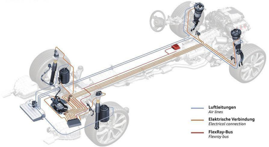
Figure
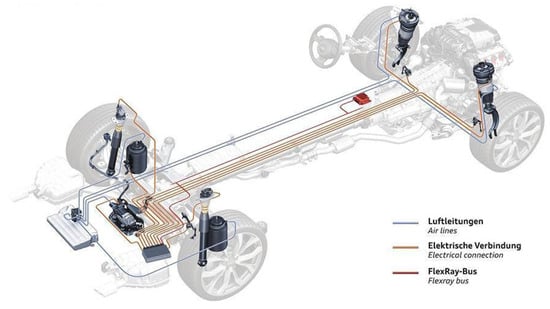
Basic structure of air suspension
The wire-controlled suspension system usually has two sets of information collection and control systems in parallel, and solving the control coupling of different systems under different road conditions is its control difficulty; The current mainstream control scheme is that the wire-controlled spring is generally adjusted in steady-state, and the wire-controlled vibration reduction is generally adjusted in real-time.The wire-controlled suspension control system is a closed-loop adaptive control system that does not have an optimal solution. The core parameters need to be continuously calibrated during the calibration process based on simulation models and actual vehicle test results.PID (proportional, integral, differential) control is the most widely used and mature control method in the control field, which is widely used in the active and semi active suspension of vehicles[53]. The adjustment of proportion (single adjustment amplitude), integration (elimination of static error), and differentiation (reflecting the trend of input signal change) parameters can be achieved through simulation testing and actual vehicle testing