Your browser does not fully support modern features. Please upgrade for a smoother experience.
Submitted Successfully!
 +1 credit
Thank you for your contribution! You can also upload a video entry or images related to this topic.
For video creation, please contact our Academic Video Service.
| Version | Summary | Created by | Modification | Content Size | Created at | Operation |
|---|---|---|---|---|---|---|
| 1 | Bartosz Trybus | -- | 1058 | 2023-11-30 09:39:34 | | | |
| 2 | Camila Xu | Meta information modification | 1058 | 2023-11-30 09:47:57 | | |
Video Upload Options
We provide professional Academic Video Service to translate complex research into visually appealing presentations. Would you like to try it?
Cite
If you have any further questions, please contact Encyclopedia Editorial Office.
Hubacz, M.; Trybus, B. The Concept of a Dual-Core PLC. Encyclopedia. Available online: https://encyclopedia.pub/entry/52218 (accessed on 24 June 2026).
Hubacz M, Trybus B. The Concept of a Dual-Core PLC. Encyclopedia. Available at: https://encyclopedia.pub/entry/52218. Accessed June 24, 2026.
Hubacz, Marcin, Bartosz Trybus. "The Concept of a Dual-Core PLC" Encyclopedia, https://encyclopedia.pub/entry/52218 (accessed June 24, 2026).
Hubacz, M., & Trybus, B. (2023, November 30). The Concept of a Dual-Core PLC. In Encyclopedia. https://encyclopedia.pub/entry/52218
Hubacz, Marcin and Bartosz Trybus. "The Concept of a Dual-Core PLC." Encyclopedia. Web. 30 November, 2023.
Copy Citation
IEC 61131-3-compliant engineering environments consist of IDE (integrated development environment) with language editors, compiler of source programs into binary code, and runtime for execution of the code. In a dual-core PLC proposed here, the cores run different projects cooperating by shared memory.
dual-core
PLC
IEC 61131-3 environment
1. Notes on the IEC 61131-3 Standard
There is a common view among practicing engineers and university staff that runtime engineering environments based on the IEC 61131-3 standard [1] will remain a state of industrial practice at least until the end of this decade. The standard defines five programming languages, namely textual IL, ST, graphic LD, FBD, and mixed SFC, with time-triggered scan cycle or event-driven execution. IL, LD, and SFC are preferred in manufacturing based on PLCs, whereas ST, FBD, and also SFC dominate in general automation.
The IEC 61131-3 introduces the concept of program organization units (POUs), such as programs, function blocks, and functions. Variables are local in a POU where they are declared, or global if the scope applies to the whole project. Global variables are used for communication.
Software environments implementing the standard, for instance CODESYS [2], STEP7 [3], automation builder [4], LogicLab [5], or others, consist of three essential components, namely IDE, compiler, and runtime. IDE provides editors of the IEC 61131-3 languages, and then compiler translates the source program into executable binary code transferred to the runtime in the controller processor. The runtime executes the code in real-time with a given cycle or when an event occurs. The addresses of global variables are also provided by the compiler.
2. General Architecture of a Dual-Core PLC
The dual-core PLC being developed may be viewed as equivalent to two separate PLCs with some communication link. Here, the link is provided by the shared memory. Figure 1 shows the general architecture, where Projects 1, 2 represent software of the PLC cores. It is assumed that each of them can also operate independently using its own local memory.
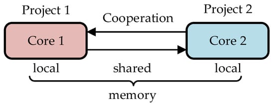
Figure 1. General architecture of a dual-core PLC.
The runtimes of the cores are copies of a single-core runtime with some minor extensions (see Section 4). Cooperation of the cores through the shared memory is provided by means of global variables.
3. Shared Global Variables
Define the following sets of global variables:
GV1—variables updated in Project 1 and used in Project 2.
GV2—variables updated in Project 2 and used in Project 1.
GV = GV1 ∪ GV2—variables shared between Projects 1, 2.
The sets are depicted in Figure 2. The areas outside the GV1 ∪ GV2 circles indicate other global variables declared in the projects but not shared.
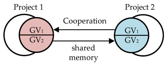
Figure 2. Sets of global variables in the two projects.
To make cooperation of the projects feasible, the original single-core designs must obey the following rule:
-
Declaration of global variables in each of the two projects must contain all shared variables, i.e., the GV set.
Note that application of the rule requires also an extension to GV variable declaration in IDE, so as to indicate whether the variable is updated in the particular project or not. It may be implemented as an additional attribute of the variable, for instance, with WRITE meaning updating in the shared memory the value and READ meaning reading only. Naturally, a GV variable cannot be declared updated in both projects.
4. Improvement of Memory Organization
It seems quite probable in industrial practice that the variables from the sets GV1, GV2 will not be declared one after another, but will be scattered among other global variables. Transfer of such scattered variables to/from the shared memory would have to be performed individually, one by one. To make the transfer more time-efficient, the scattered GV1, GV2 variables may be collected into compact memory sectors transferred by fast memory copying. An extension of the single-core compiler for the dual-core application is needed to make such an ordered arrangement. The recommended memory organization after the arrangement is shown in Figure 3.
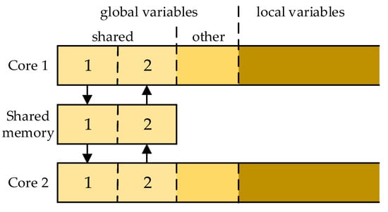
Figure 3. Memory organization of the dual-core PLC.
After such an arrangement, the relevant sectors of Core 1 memory may be denoted as:
-
CM11—sector for GV1 (updated WRITE, another words output);
-
CM12—sector for GV2 (received READ—input).
Likewise, we have CM21 (input), CM22 (output) for Core 2, and SH1, SH2 for the shared memory.
5. Operation of a Dual-Core PLC
During execution of the binary code, the runtime programs of typical PLCs apply read-execute-write semantics for the scan cycle. This means that all input values are read into internal local copies once a program starts its execution at the beginning of the cycle. During the remainder of the execution, only those local values are used (the mechanism is sometimes called a process image). At the end of the execution, the output values are written into global copies to be used in the next cycle.
In case of Core 1, the content of CM12 memory becomes the input (see Figure 3). However, so far, it is stored in SH2, where it has been copied earlier from CM22, once Core 2 finished its execution. Hence, at the beginning of the Core 1 cycle, SH2 must be copied into CM12. At the end of the execution, the results updated in CM11 are copied into SH1. So, the beginning of execution and the end of the cycles of two cooperating cores may be illustrated as in Figure 4. To implement such behavior, the original single-core runtime must be extended by the copy-from the shared memory at the beginning of the cycle and copy-to at the end. Note that operations executed at the beginning may be called precycle, whereas those executed at the end may be called postcycle.
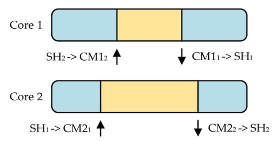
Figure 4. Scan cycles of the dual-core PLC.
To avoid conflicts between the cores while accessing the shared memory, multi-core processors have built-in hardware semaphores to check whether access is currently possible. Runtime software of each core must involve an algorithm for operating the semaphore, so raising it (releasing) when the data transfer is completed. An example of such an algorithm is shown in Section 5.
To summarize, three extensions of a typical single-core IEC 61131-3 runtime engineering environment are needed for implementation into dual-core PLC running two projects:
-
IDE: an additional attribute of a shared global variable to indicate whether it is updated in the actual core or received from the other one.
-
Compiler: memory arrangement so as to have updated and received shared variables in compact sectors (optional).
-
Runtime: copy-from the shared memory at the beginning of the cycle (precycle) and copy-to at the end (postcycle).
References
- John, K.H.; Tiegelkamp, M. IEC 61131-3: Programming Industrial Automation Systems; Springer: Berlin/Heidelberg, Germany, 2010.
- CODESYS. Available online: https://www.codesys.com/ (accessed on 11 October 2023).
- SIMATIC STEP 7 (TIA Portal). SIEMENS. Available online: https://www.siemens.com/global/en/products/automation/industry-software/automation-software/tia-portal/software/step7-tia-portal.html (accessed on 11 October 2023).
- Automation Builder. Available online: https://new.abb.com/plc/automationbuilder (accessed on 11 October 2023).
- LogicLab. Available online: https://www.axelsoftware.it/en/logiclab/ (accessed on 11 October 2023).
More
Information
Contributors
MDPI registered users' name will be linked to their SciProfiles pages. To register with us, please refer to https://encyclopedia.pub/register
:
View Times:
497
Revisions:
2 times
(View History)
Update Date:
30 Nov 2023
Table of Contents


Notice
You are not a member of the advisory board for this topic. If you want to update advisory board member profile, please contact office@encyclopedia.pub.
OK
Confirm
Only members of the Encyclopedia advisory board for this topic are allowed to note entries. Would you like to become an advisory board member of the Encyclopedia?
Yes
No
${ textCharacter }/${ maxCharacter }
Submit
Cancel
Back
Comments
${ item }
|
${ item.createdUser.fullName }
${ item.createdAt }
${ item.vote }
${ item.reply }
Delete
${ reply.createdUser.fullName }
${ reply.createdAt }
${ reply.vote }
Delete
There is no reply to this comment~
${ item.replyTextCharacter }/${ item.replyMaxCharacter }
Submit
Cancel
More
No more~
There is no comment~
${ textCharacter }/${ maxCharacter }
Submit
Cancel
${ selectedItem.replyTextCharacter }/${ selectedItem.replyMaxCharacter }
Submit
Cancel
Confirm
Are you sure to Delete?
Yes
No