Your browser does not fully support modern features. Please upgrade for a smoother experience.
Submitted Successfully!
 +1 credit
Thank you for your contribution! You can also upload a video entry or images related to this topic.
For video creation, please contact our Academic Video Service.
| Version | Summary | Created by | Modification | Content Size | Created at | Operation |
|---|---|---|---|---|---|---|
| 1 | York Castillo Santiago | -- | 1470 | 2023-08-16 12:31:11 | | | |
| 2 | Lindsay Dong | + 106 word(s) | 1576 | 2023-08-17 03:13:01 | | | | |
| 3 | Lindsay Dong | + 5 word(s) | 1581 | 2023-08-17 03:13:56 | | |
Video Upload Options
We provide professional Academic Video Service to translate complex research into visually appealing presentations. Would you like to try it?
Cite
If you have any further questions, please contact Encyclopedia Editorial Office.
Castillo Santiago, Y.; Nunes, B.G.; Fontana, G.S.; Busanello, D.; Santos, A.F.; Santos, S.M.D.; Mello, E.N.D.; Sphaier, L.A. Desiccant Technologies: An Overview of the Brazilian Scenario. Encyclopedia. Available online: https://encyclopedia.pub/entry/48126 (accessed on 25 June 2026).
Castillo Santiago Y, Nunes BG, Fontana GS, Busanello D, Santos AF, Santos SMD, et al. Desiccant Technologies: An Overview of the Brazilian Scenario. Encyclopedia. Available at: https://encyclopedia.pub/entry/48126. Accessed June 25, 2026.
Castillo Santiago, York, Bruno Gomes Nunes, Geovani Souza Fontana, Daiane Busanello, Alexandre Fernandes Santos, Samuel Moreira Duarte Santos, Estefania Neiva De Mello, Leandro A. Sphaier. "Desiccant Technologies: An Overview of the Brazilian Scenario" Encyclopedia, https://encyclopedia.pub/entry/48126 (accessed June 25, 2026).
Castillo Santiago, Y., Nunes, B.G., Fontana, G.S., Busanello, D., Santos, A.F., Santos, S.M.D., Mello, E.N.D., & Sphaier, L.A. (2023, August 16). Desiccant Technologies: An Overview of the Brazilian Scenario. In Encyclopedia. https://encyclopedia.pub/entry/48126
Castillo Santiago, York, et al. "Desiccant Technologies: An Overview of the Brazilian Scenario." Encyclopedia. Web. 16 August, 2023.
Copy Citation
This research assessed alternatives for air Heating, Ventilation, and Air Conditioning (HVAC) systems to minimize Sick Building Syndrome and improve air quality while considering international programs/standards. For this purpose, an alternative technology known as desiccant wheels was studied by analyzing their principles and types when the existing selection software for these types of equipment was performed. In addition, energy-efficiency programs worldwide and in the Brazilian context were analyzed while aiming at implementing strategies in which desiccant wheels are appropriate. Finally, some examples of commercial software for desiccant wheels were compared to identify the different tools available in the air conditioning market.
dehumidification
desiccant wheels
air quality
air conditioning systems
1. Background
In 1951, Carl Munters filed a patent for a desiccant-based drying system. He realized the potential for attracting water molecules and materials such as silica gel. This concept began the process and development of drying technology using desiccant wheels [1].
Desiccant wheels (Figure 1) are based on a wheel with desiccant crystals impregnated and grown on a fiberglass substrate. The lightweight wheel has a high surface-area-to-airflow ratio [2]. The desiccant wheel is a passive desiccant wheel or enthalpy wheel when there is no regeneration air heater. At the same time, it is called an active desiccant wheel when it is provided with an air heater, and the regeneration and process air sides are slatted apart. The wheel is installed with thermal insulation and air-proof material so there is no mass and energy exchange with the surroundings [3].

Figure 1. Desiccant wheel [3].
During operation, the wheel rotates continuously, and the desiccant cycles through adsorption, regeneration, and cooling every 4–5 min. Drying air is constantly regenerated in a closed circuit. The hot regeneration air passes through the desiccant medium, releasing the released moisture into the atmosphere [4]. No ambient air is introduced into the process because desiccant cooling is conducted using dry air. The desired dew point is achieved by changing the spin speed and other dryer variables without excessively drying the thermally sensitive materials [5]. Desiccant wheels are used in various heating and residential environments to prevent the growth of mold and mildew. As conventional air conditioning systems are limited, desiccants remove moisture (latent energy) in hot and humid climates [6].

2. Types of Desiccant Dehumidification Systems
2.1. Spray Drying Tower
The spray drying tower has two tanks corresponding to the condenser and the regenerator. In this system, the humid air enters the segment of the condenser and passes through a saline fog that will capture the humidity of the air while the dry air is inflated for the process. At the bottom of the condenser tank, the saline solution is pumped to the second tank (regenerator), through which the second flow of high-temperature external air passes, causing the saline solution to lose moisture to the regeneration air. Thus, the hygroscopic material returns to the condenser tank [7].
2.2. Dual-Tower Desiccant Dryers
The dual-tower desiccant dryers have two vessels (one for process and another for regeneration), as shown in Figure 2; each vessel has solid silica gel inside. Moist air passes through the first pressurized cylinder, trapping moisture in the silica gel until it saturates the hygroscopic material. After the saturation of the first cylinder, the direction of the process air to the second cylinder is reversed, the first being regenerated with external and heated air [8].
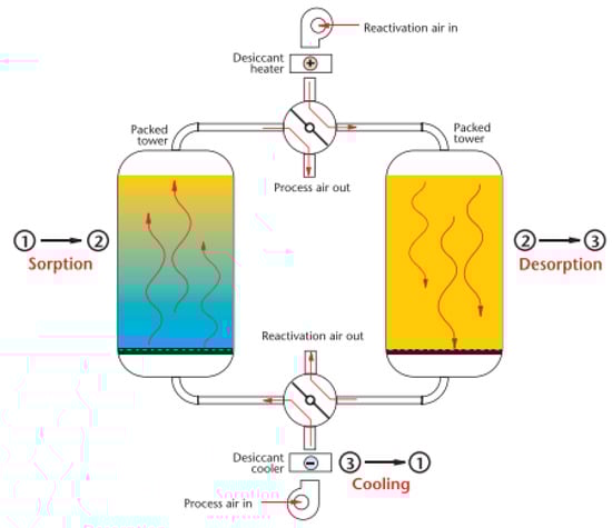
Figure 2. Dual-tower desiccant dryer scheme. Source: [9].
2.3. Tray Dryer
The spray dryer has two air flows (process and regeneration), as presented in Figure 3. The hygroscopic material responsible for capturing the humidity from the air is arranged in trays; the humid air passes through the process air sector, and the external air of the regeneration passes through 1/4 of the trays. The trays rotate so the silica gel passes from the process to the regeneration sector [10].
Figure 3. Tray dryer scheme. Source: [9].
2.4. Multi-Belt Dryer
The multi-belt dryer has two streams of trays arranged vertically (Figure 4) in which the granular hygroscopic material is installed, and the humid process air passes through the trays. After the silica gel saturation, the tray rotates to the regeneration sector, where the moisture impregnated on the silica gel is eliminated [11].
Figure 4. Multi-belt dryer scheme. Source: [9].
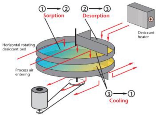
2.5. Desiccant Dehumidifier
Figure 5 shows the working principle of the desiccant dehumidifier, which has two air flows; the first occupies ¾ of the wheel and is responsible for adsorbing all excess moisture from the air. After the air passes through the rotor, it is inflated with low moisture content [12].
Figure 5. Desiccant dehumidifier scheme. Source: [9].
The second airflow, called regeneration air, occupies ¼ of the rotor and is responsible for extracting moisture in a vapor state from the desiccant rotor using a flow of heated air. The rotor structure is constructed in the shape of a beehive in order to have the largest possible area of hygroscopic material in contact with the air [13]. The hygroscopic material may be silica gel or a mixture of silica gel and zeolites [14].
3. Desiccant Dehumidification by Heat-Recovery Wheel
Heat-recovery wheels have different operating characteristics from desiccant wheels; their main objective is to promote heat transfer and humidity between the two existing air flows in the equipment [15]. These types of equipment also can minimize cross-contamination due to exhaust and supply airflows and provide high-efficiency systems with a low-pressure drop in the airflows [16]. Thus, some technologies, such as cross-flow heat exchangers and enthalpy wheels were developed [17].
3.1. Enthalpy Wheels
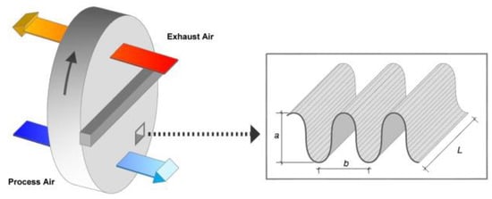
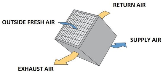
The rotary heat exchanger (Figure 6), commonly known as an enthalpy wheel, is an “air-air”-type heat exchanger that works on the principle of sensible heat (temperature) and latent heat (humidity) exchange between the flow of renewal air and the flow of exhaust air [18]. Enthalpy wheels can be classified as sensible heat wheels and enthalpy wheels. The denomination for these two types is due to their application, where the sensible heat wheels act with the function of only exchanging the sensible heat, while the enthalpy wheel works completely between the energies of the air (the sensible heat and the latent heat). These two processes occur between the two air masses that travel through the equipment [19].
Figure 6. Enthalpy wheel [18].
The enthalpy wheel is an essential piece of equipment for building air-treatment systems that has some advantages and disadvantages. As an advantage, it can be mentioned that it is a technology that reaches efficiencies of around 50% to 80% [20]. Its operation and high operating flows provide energy savings since the cooling system that works after the enthalpy wheel can have a lower cooling load than the conventional one (without using the enthalpy wheel) [21]. For any design to meet the Green Building certifications, some minimum assumptions must be met, including the rate of air renewal of the central systems. Thus, it is possible to reduce the size of the cooling or heating coils of the air-treatment units [22]. Its main disadvantage is the initial investment in the system; however, this value has a short payback period [23].
3.2. Cross-Flow Heat Exchangers
The cross-flow heat exchanger is an “air-to-air” static heat exchanger. Like the enthalpy wheel, the cross-flow heat exchanger can be classified into two types [24]. The sensible cross-flow heat exchanger performs the function of only sensible heat exchange between the two air masses, and the conventional cross-flow heat exchanger (Figure 7) exchanges sensible heat and latent heat during the thermal exchange process of the equipment [25].
Figure 7. Cross-flow heat exchangers.
Cross-flow heat exchangers are generally used for gas-to-liquid heat-transfer applications in which the gas is on the outside and the liquid is on the tube side of the heat exchanger. Most of these exchangers have fins that increase the surface area and improve heat transfer. In most sensible heat-transfer applications, the external fluid is treated as unmixed flow, while the tube-side fluid is treated as mixed flow [26]. Nasif [27] found that cross-flow heat exchangers significantly reduce energy consumption. They reduces the latent load in hot and humid environments and provide 100% external air to the environment in question.
4. Software for Selecting Desiccant Wheels
Selecting a suitable desiccant requires that the involved dehumidification process be simulated. This can be quite time-consuming depending on the level of detail necessary for a specific simulation and a considerable amount of operating and construction data related to the wheel, as shown in previous works [28][29][30][31]. As a result, commercial software became available to facilitate the selection process of dehumidifiers while considering human breathing. This section presented software for selecting desiccant wheels provided by manufacturers, and some characteristics were analyzed
Several companies that develop heat-recovery technologies using desiccant wheels are recognized by international organizations such as Eurovent and AHR Exhibition and by Brazilian agencies such as ABRAVA and the South Brazilian Association of Refrigeration, Air Conditioning, Heating and Ventilation (ASBRAV) were studied. The research on commercial software for the technologies studied (Table 1) does not present a careful analysis of the operating results over a year; in most cases, the software only shows the efficiency and output data. In addition, it is necessary that for all software, the user must have external knowledge of thermal engineering to be able to analyze a project.
Table 1. Software comparison.
| Novel Aire | Munters | Rotor Source | Puresci | |
|---|---|---|---|---|
| Input data | ||||
| Process inlet dry bulb temperature | X | X | X | X |
| Absolute humidity entering the process | X | X | X | X |
| Regeneration inlet dry bulb temperature | X | X | X | X |
| Absolute inlet humidity in regeneration | X | X | X | X |
| Dry bulb temperature after heating in regeneration | X | X | X | X |
| Output data | ||||
| Output dry bulb temperature in the process | X | X | X | X |
| Output absolute humidity in the process | X | X | X | X |
| Dry bulb temperature after regeneration output | X | X | X | X |
| Output absolute humidity at regeneration output | X | X | X | X |
| Moisture removal charge | X | X | ||
References
- Munters Munters’ Desiccant Rotor—Industrial Dehumidification at Its Best. Available online: https://www.munters.com/en/about-us/history-of-munters/history-news2/munters-desiccant-rotor--industrial-dehumidification-at-its-best/ (accessed on 11 July 2022).
- Kent, R. Services. In Energy Management in Plastics Processing; Kent, R., Ed.; Elsevier: Oxford, UK, 2018; pp. 105–210. ISBN 978-0-08-102507-9.
- Narayanan, R. Heat-Driven Cooling Technologies. In Clean Energy for Sustainable Development; Rasul, M.G., Azad, A.K., Sharma, S., Eds.; Academic Press: Oxford, UK, 2017; pp. 191–212. ISBN 978-0-12-805423-9.
- Rambhad, K.S.; Walke, P.V.; Tidke, D.J. Solid Desiccant Dehumidification and Regeneration Methods—A Review. Renew. Sustain. Energy Rev. 2016, 59, 73–83.
- Guan, B.; Liu, X.; Zhang, T. Investigation of a Compact Hybrid Liquid-Desiccant Air-Conditioning System for Return Air Dehumidification. Build. Environ. 2021, 187, 107420.
- ASHRAE. 2019 ASHRAE Handbook_HVAC Applications CH35.Pdf; ASHRAE: Orlando, FL, USA, 2019; ISBN 9781947192133.
- Kojok, F.; Fardoun, F.; Younes, R.; Outbib, R. Hybrid Cooling Systems: A Review and an Optimized Selection Scheme. Renew. Sustain. Energy Rev. 2016, 65, 57–80.
- Ling-Chin, J.; Bao, H.; Ma, Z.; Roskilly, W.T. State-of-the-Art Technologies on Low-Grade Heat Recovery and Utilization in Industry. In Energy Conversion—Current Technologies and Future Trends; Al-Bahadly, I.H., Ed.; IntechOpen: Rijeka, Italy, 2018; pp. 55–74. ISBN 978-1-78984-905-9.
- Munters. Dehumidificaion Handbook, 3rd ed.; Munters Corporation, Ed.; Munters Corporation Marketing Department: Amesbury, MA, USA, 2019; ISBN 2013206534.
- Mujumdar, A.S.; Huang, L.-X.; Chen, X.D. An Overview of the Recent Advances in Spray-Drying. Dairy Sci. Technol. 2010, 90, 211–224.
- Zhang, H.; Pang, B.; Kang, S.; Fu, J.; Tang, P.; Chang, J.; Li, J.; Li, Z.; Deng, S. The Influence of Feedstock Stacking Shape on the Drying Performance of Conveyor Belt Dryer. Heat Mass Transf. 2022, 58, 157–170.
- Li, X. Analysis on the Utilization of Temperature and Humidity Independent Control Air-Conditioning System with Different Fresh-Air Handling Methods. Procedia Eng. 2017, 205, 71–78.
- Chen, T.; Norford, L. Energy Performance of Next-Generation Dedicated Outdoor Air Cooling Systems in Low-Energy Building Operations. Energy Build. 2020, 209, 109677.
- Gado, M.G.; Nasser, M.; Hassan, A.A.; Hassan, H. Adsorption-Based Atmospheric Water Harvesting Powered by Solar Energy: Comprehensive Review on Desiccant Materials and Systems. Process. Saf. Environ. Prot. 2022, 160, 166–183.
- Nizovtsev, M.I.; Borodulin, V.Y.; Letushko, V.N. Influence of Condensation on the Efficiency of Regenerative Heat Exchanger for Ventilation. Appl. Therm. Eng. 2017, 111, 997–1007.
- Calautit, J.K.; O’Connor, D.; Tien, P.W.; Wei, S.; Pantua, C.A.J.; Hughes, B. Development of a Natural Ventilation Windcatcher with Passive Heat Recovery Wheel for Mild-Cold Climates: CFD and Experimental Analysis. Renew. Energy 2020, 160, 465–482.
- Xu, Q.; Riffat, S.; Zhang, S. Review of Heat Recovery Technologies for Building Applications. Energies 2019, 12, 1285.
- Men, Y.; Liu, X.; Zhang, T. A Review of Boiler Waste Heat Recovery Technologies in the Medium-Low Temperature Range. Energy 2021, 237, 121560.
- Herath, H.M.D.P.; Wickramasinghe, M.D.A.; Polgolla, A.M.C.K.; Jayasena, A.S.; Ranasinghe, R.A.C.P.; Wijewardane, M.A. Applicability of Rotary Thermal Wheels to Hot and Humid Climates. Energy Rep. 2020, 6, 539–544.
- Liu, Z.; Li, W.; Chen, Y.; Luo, Y.; Zhang, L. Review of Energy Conservation Technologies for Fresh Air Supply in Zero Energy Buildings. Appl. Therm. Eng. 2019, 148, 544–556.
- Jani, D.B.; Mishra, M.; Sahoo, P.K. Solid Desiccant Air Conditioning—A State of the Art Review. Renew. Sustain. Energy Rev. 2016, 60, 1451–1469.
- Altomonte, S.; Schiavon, S.; Kent, M.G.; Brager, G. Indoor Environmental Quality and Occupant Satisfaction in Green-Certified Buildings. Build. Res. Inf. 2019, 47, 255–274.
- Zender–Świercz, E. A Review of Heat Recovery in Ventilation. Energies 2021, 14, 1759.
- Wang, Y.; Wang, L.; Huang, Q.; Cui, Y. Experimental and Theoretical Investigation of Cross-Flow Heat Transfer Equipment for Air Energy High Efficient Utilization. Appl. Therm. Eng. 2016, 98, 1231–1240.
- Hye-Cho, J.; Cheon, S.-Y.; Jeong, J.-W. Development of empirical models to predict latent heat exchange performance for hollow fiber membrane-based ventilation system. Appl. Therm. Eng. 2022, 213, 118686.
- Silaipillayarputhur, K.; Al-Mughanam, T. Performance of Pure Crossflow Heat Exchanger in Sensible Heat Transfer Application. Energies 2021, 14, 5489.
- Nasif, M.S. Air-to-Air Fixed Plate Energy Recovery Heat Exchangers for Building’s HVAC Systems. In Sustainable Thermal Power Resources through Future Engineering; Sulaiman, S.A., Ed.; Springer: Singapore, 2019; pp. 63–71. ISBN 9789811329685.
- Santos, S.M.D.; Sphaier, L.A. Transient Formulation for Evaluating Convective Coefficients in Regenerative Exchangers with Hygroscopic Channels. Int. Commun. Heat Mass Transf. 2020, 116, 104691.
- Sphaier, L.A.; Worek, W.M. Parametric Analysis of Heat and Mass Transfer Regenerators Using a Generalized Effectiveness-NTU Method. Int. J. Heat Mass Transf. 2009, 52, 2265–2272.
- Sphaier, L.A.; Worek, W.M. Numerical Solution of Periodic Heat and Mass Transfer with Adsorption in Regenerators: Analysis and Optimization. Numer. Heat Transf. A Appl. 2008, 53, 1133–1155.
- Sphaier, L.A.; Worek, W.M. The Effect of Axial Diffusion in Desiccant and Enthalpy Wheels. Int. J. Heat Mass Transf. 2006, 49, 1412–1419.
More
Information
Subjects:
Engineering, Mechanical
Contributors
MDPI registered users' name will be linked to their SciProfiles pages. To register with us, please refer to https://encyclopedia.pub/register
:
View Times:
1.8K
Revisions:
3 times
(View History)
Update Date:
17 Aug 2023
Table of Contents


Notice
You are not a member of the advisory board for this topic. If you want to update advisory board member profile, please contact office@encyclopedia.pub.
OK
Confirm
Only members of the Encyclopedia advisory board for this topic are allowed to note entries. Would you like to become an advisory board member of the Encyclopedia?
Yes
No
${ textCharacter }/${ maxCharacter }
Submit
Cancel
Back
Comments
${ item }
|
${ item.createdUser.fullName }
${ item.createdAt }
${ item.vote }
${ item.reply }
Delete
${ reply.createdUser.fullName }
${ reply.createdAt }
${ reply.vote }
Delete
There is no reply to this comment~
${ item.replyTextCharacter }/${ item.replyMaxCharacter }
Submit
Cancel
More
No more~
There is no comment~
${ textCharacter }/${ maxCharacter }
Submit
Cancel
${ selectedItem.replyTextCharacter }/${ selectedItem.replyMaxCharacter }
Submit
Cancel
Confirm
Are you sure to Delete?
Yes
No