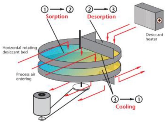
2.3. Tray Dryer
The spray dryer has two air flows (process and regeneration), as presented in
Figure 7. The hygroscopic material responsible for capturing the humidity from the air is arranged in trays; the humid air passes through the process air sector, and the external air of the regeneration passes through 1/4 of the trays. The trays rotate so the silica gel passes from the process to the regeneration sector [
66].
Figure 7. Tray dryer scheme. Source: [
64].
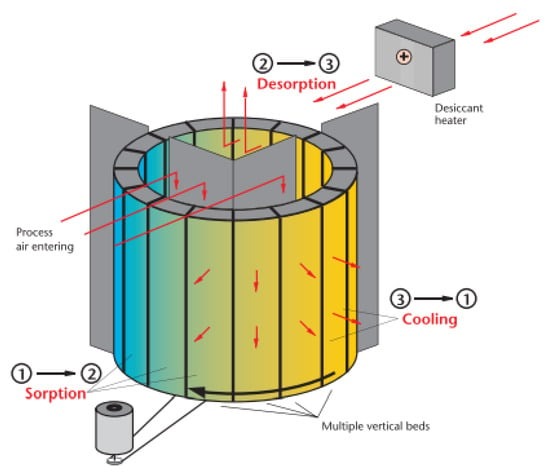
2.4. Multi-Belt Dryer
The multi-belt dryer has two streams of trays arranged vertically (
Figure 8) in which the granular hygroscopic material is installed, and the humid process air passes through the trays. After the silica gel saturation, the tray rotates to the regeneration sector, where the moisture impregnated on the silica gel is eliminated [
67].
Figure 8. Multi-belt dryer scheme. Source: [
64].
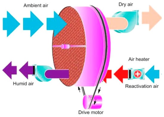
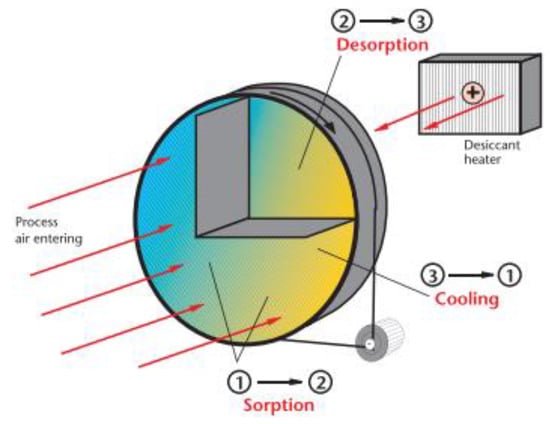
2.5. Desiccant Dehumidifier
Figure 9 shows the working principle of the desiccant dehumidifier, which has two air flows; the first occupies ¾ of the wheel and is responsible for adsorbing all excess moisture from the air. After the air passes through the rotor, it is inflated with low moisture content [
68].
Figure 9. Desiccant dehumidifier scheme. Source: [
64].
The second airflow, called regeneration air, occupies ¼ of the rotor and is responsible for extracting moisture in a vapor state from the desiccant rotor using a flow of heated air. The rotor structure is constructed in the shape of a beehive in order to have the largest possible area of hygroscopic material in contact with the air [
69]. The hygroscopic material may be silica gel or a mixture of silica gel and zeolites [
70].
3. Desiccant Dehumidification by Heat-Recovery Wheel
Heat-recovery wheels have different operating characteristics from desiccant wheels; their main objective is to promote heat transfer and humidity between the two existing air flows in the equipment [
71]. These types of equipment also can minimize cross-contamination due to exhaust and supply airflows and provide high-efficiency systems with a low-pressure drop in the airflows [
72]. Thus, some technologies, such as cross-flow heat exchangers and enthalpy wheels were developed [
73].
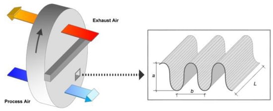
3.1. Enthalpy Wheels
The rotary heat exchanger (
Figure 10), commonly known as an enthalpy wheel, is an “air-air”-type heat exchanger that works on the principle of sensible heat (temperature) and latent heat (humidity) exchange between the flow of renewal air and the flow of exhaust air [
74]. Enthalpy wheels can be classified as sensible heat wheels and enthalpy wheels. The denomination for these two types is due to their application, where the sensible heat wheels act with the function of only exchanging the sensible heat, while the enthalpy wheel works completely between the energies of the air (the sensible heat and the latent heat). These two processes occur between the two air masses that travel through the equipment [
75].
Figure 10. Enthalpy wheel [
74].
The enthalpy wheel is an essential piece of equipment for building air-treatment systems that has some advantages and disadvantages. As an advantage, it can be mentioned that it is a technology that reaches efficiencies of around 50% to 80% [
76]. Its operation and high operating flows provide energy savings since the cooling system that works after the enthalpy wheel can have a lower cooling load than the conventional one (without using the enthalpy wheel) [
77]. For any design to meet the Green Building certifications, some minimum assumptions must be met, including the rate of air renewal of the central systems. Thus, it is possible to reduce the size of the cooling or heating coils of the air-treatment units [
78]. Its main disadvantage is the initial investment in the system; however, this value has a short payback period [
79].
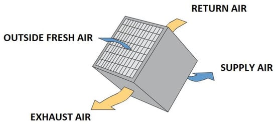
3.2. Cross-Flow Heat Exchangers
The cross-flow heat exchanger is an “air-to-air” static heat exchanger. Like the enthalpy wheel, the cross-flow heat exchanger can be classified into two types [
80]. The sensible cross-flow heat exchanger performs the function of only sensible heat exchange between the two air masses, and the conventional cross-flow heat exchanger (
Figure 11) exchanges sensible heat and latent heat during the thermal exchange process of the equipment [
81].
Figure 11. Cross-flow heat exchangers.
Cross-flow heat exchangers are generally used for gas-to-liquid heat-transfer applications in which the gas is on the outside and the liquid is on the tube side of the heat exchanger. Most of these exchangers have fins that increase the surface area and improve heat transfer. In most sensible heat-transfer applications, the external fluid is treated as unmixed flow, while the tube-side fluid is treated as mixed flow [
82]. Nasif [
83] found that cross-flow heat exchangers significantly reduce energy consumption. They reduces the latent load in hot and humid environments and provide 100% external air to the environment in question.
4. Software for Selecting Desiccant Wheels
Selecting a suitable desiccant requires that the involved dehumidification process be simulated. This can be quite time-consuming depending on the level of detail necessary for a specific simulation and a considerable amount of operating and construction data related to the wheel, as shown in previous works [
84,
85,
86,
87]. As a result, commercial software became available to facilitate the selection process of dehumidifiers while considering human breathing. This section presented software for selecting desiccant wheels provided by manufacturers, and some characteristics were analyzed
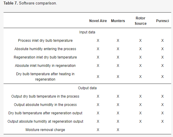
Several companies that develop heat-recovery technologies using desiccant wheels are recognized by international organizations such as Eurovent and AHR Exhibition and by Brazilian agencies such as ABRAVA and the South Brazilian Association of Refrigeration, Air Conditioning, Heating and Ventilation (ASBRAV) were studied. The research on commercial software for the technologies studied (Table 7) does not present a careful analysis of the operating results over a year; in most cases, the software only shows the efficiency and output data. In addition, it is necessary that for all software, the user must have external knowledge of thermal engineering to be able to analyze a project.