 +1 credit
| Version | Summary | Created by | Modification | Content Size | Created at | Operation |
|---|---|---|---|---|---|---|
| 1 | Mickaël Castro | -- | 4762 | 2022-04-07 17:11:45 | | | |
| 2 | Lindsay Dong | -16 word(s) | 4746 | 2022-04-08 07:30:30 | | | | |
| 3 | Lindsay Dong | Meta information modification | 4746 | 2022-04-08 07:37:31 | | |
Video Upload Options
The growing demands for electrical energy, especially renewable, is boosting the development of wind turbines equipped with longer composite blades. To reduce the maintenance cost of huge composite parts, the structural health monitoring (SHM) is an approach to anticipate and/or follow the structural behaviour along time. Apart from the development of traditional non-destructive testing methods, in order to reduce the use of intrusive instrumentation there is a growing interest for the development of “self-sensing materials”. An interesting route to achieve this, can be to introduce carbon nanofillers such as nanotubes (CNT) in the composite structures, which enables to create systems that are sensitive to both strain and damage.
1. Introduction
-
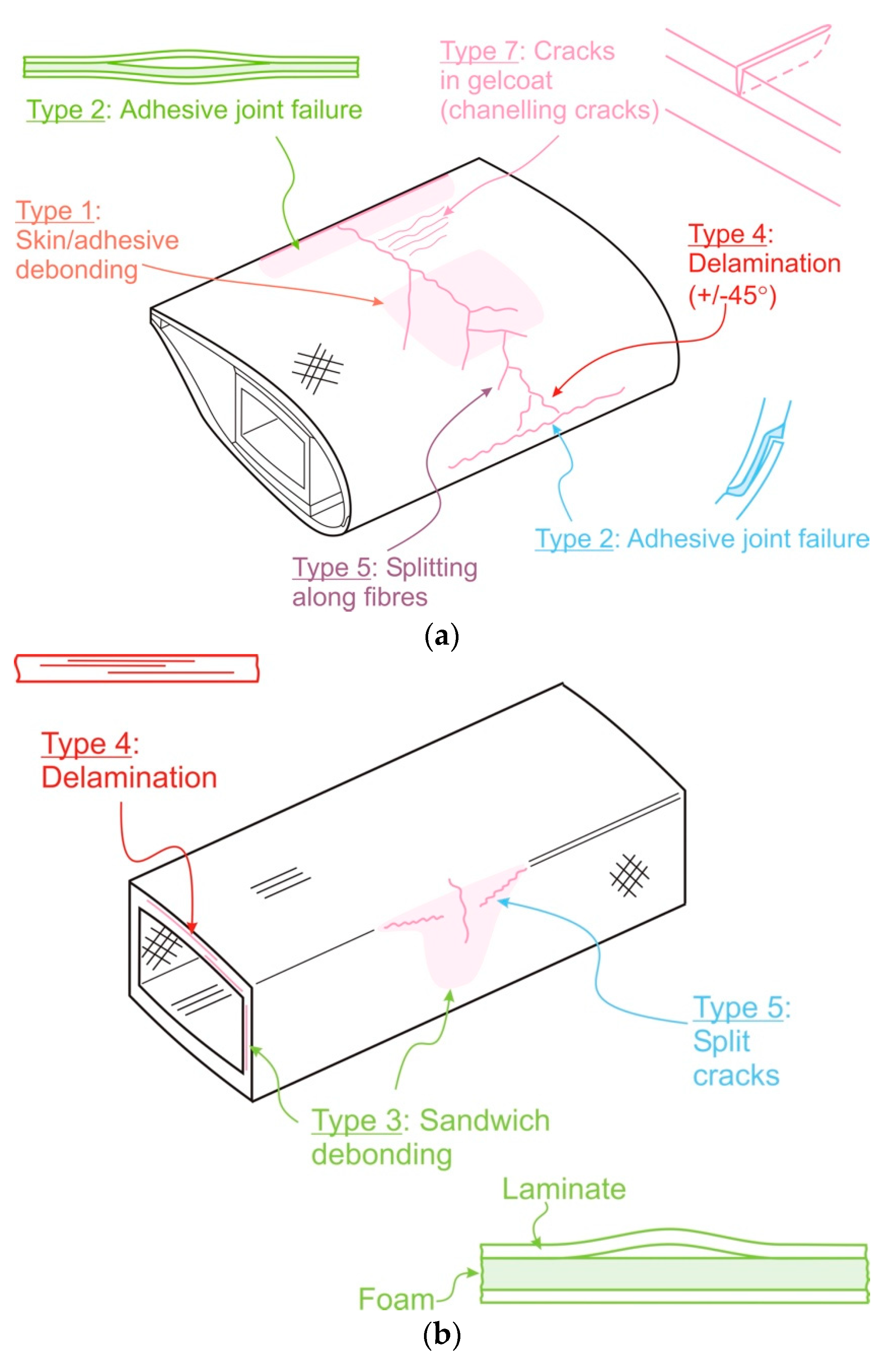
Type 1: Damage formation and growth in the adhesive layer joining skin and main spar flanges (skin/adhesive debonding and/or main spar/adhesive layer debonding),
-
Type 2: Damage formation and growth in the adhesive layer joining the up and downwind skins along leading and/or trailing edges (adhesive joint failure between skins),
-
Type 3: Damage formation and growth at the interface between face and core in sandwich panels in skins and main spar web (sandwich panel face/core debonding),
-
Type 4: Internal damage formation and growth in laminates in skin and/or main spar flanges, under a tensile or compression load (delamination driven by a tensional or a buckling load),
-
Type 5: Splitting and fracture of separate fibres in laminates of the skin and main spar (fibre failure in tension; laminate failure in compression),
-
Type 6: Buckling of the skin due to damage formation and growth in the bond between skin and main spar under compressive load (skin/adhesive debonding induced by buckling, a specific type 1 case),
-
Type 7: Formation and growth of cracks in the gel-coat; debonding of the gelcoat from the skin (gel-coat cracking and gel-coat/skin debonding).
2. Commercially Available Technics Based on Strain & Damage Monitoring
2.1. Monitoring Technics Used in Strain Analysis
2.1.1. Metallic Strain Gauges
2.1.2. Optical Fibres
2.2. Monitoring Techniques Used in Failure Analysis
2.2.1. Visual Inspection
2.2.2. Performance Analysis
2.2.3. Acoustic Emission (AE)
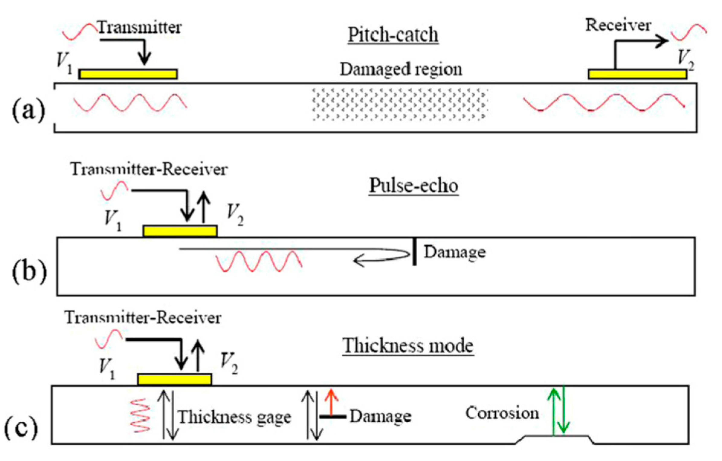
2.2.4. Ultrasonic Measurements
2.2.5. Vibrational Analysis
2.2.6. Radiography
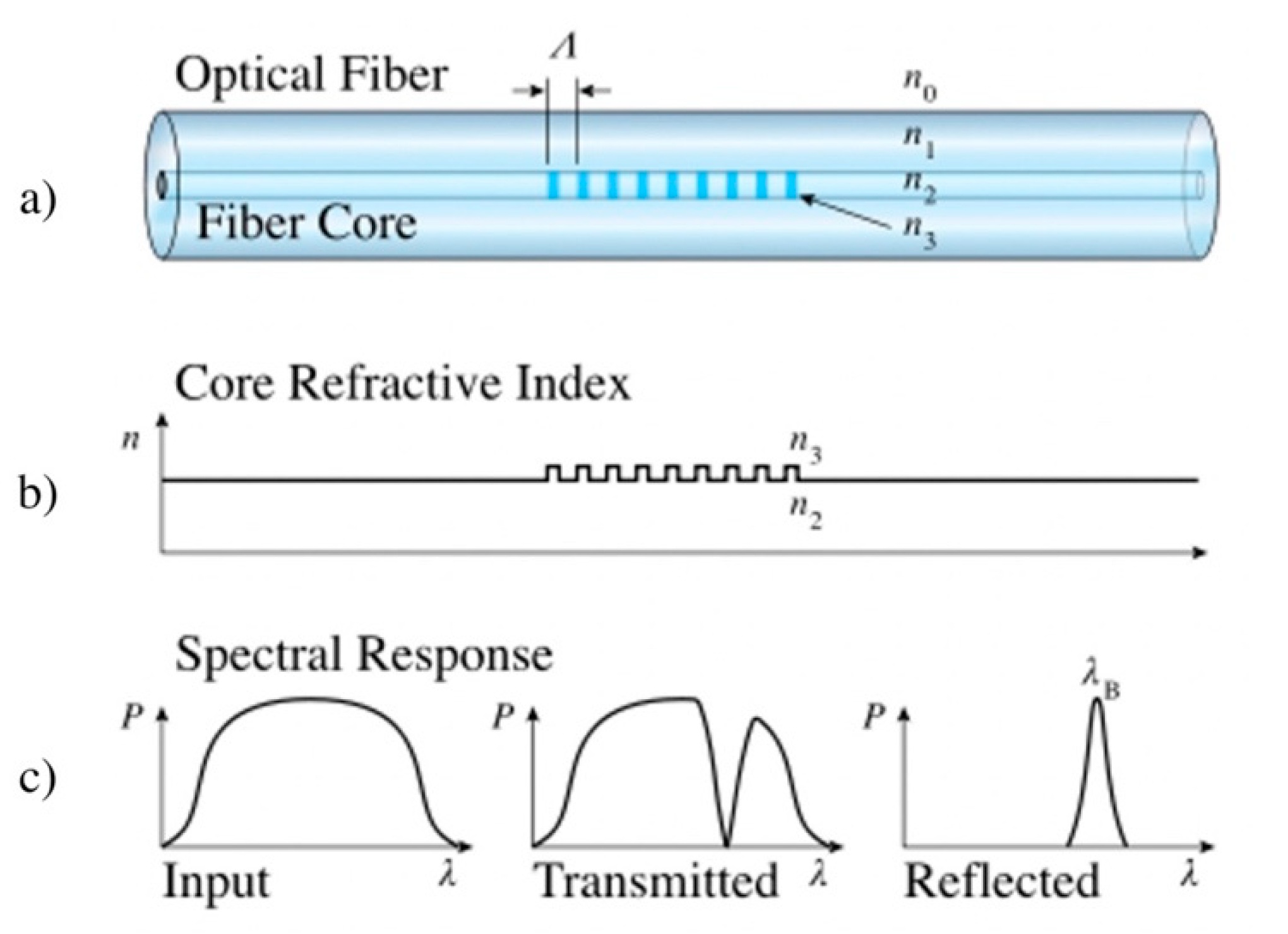
2.2.7. Optical Fibres (OF)
3. Emerging Technics Based on Self-Sensing Thermoset Composites Filled with Carbon Materials
The classical SHM and maintenance technics previously described have shown to be efficient methods for strain and damage detection. Nevertheless, most of them require either an extensive human involvement or expensive procedures. Moreover, they present partial information of the structure since they are only sensitive to strain or damage. Consequently, the combination of complementary technics appears compulsory for a suitable SHM system. To date, the use of optical fibres is the most promising technique, because firstly it can provide, at a laboratory scale, both strain and specific damages, and, secondly, unlike the other technics, the optical fibres could be embedded in the core of composite structures (their detrimental effects on the mechanical properties being acceptable). Nevertheless, their sensitivity remains lower than that of commercial metallic strain gauges, and a substantial equipment is required, as well for the fibres’ deployment as for the in-service use. Consequently, in parallel with the previously mentioned strategies, there has been a growing interest for the development of “self-sensing materials”. Those materials are prone to provide real-time information about themselves or their environment [2].
3.1. Carbon Fibre Reinforced Epoxy (CF-EP) as Self-Sensing Materials
3.2. Carbon Nanoparticles and Their Associated Nanocomposites as Self-Sensing Systems
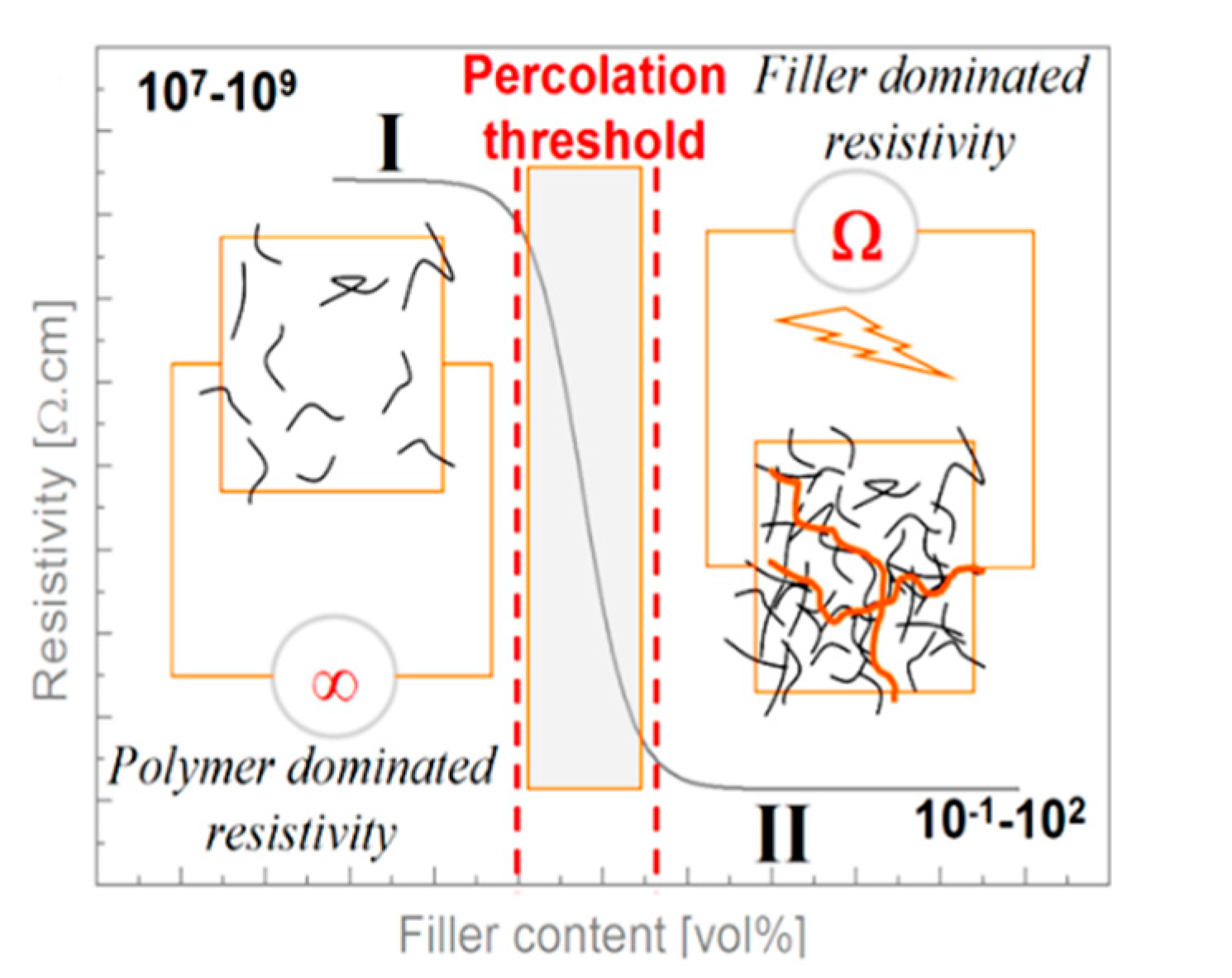
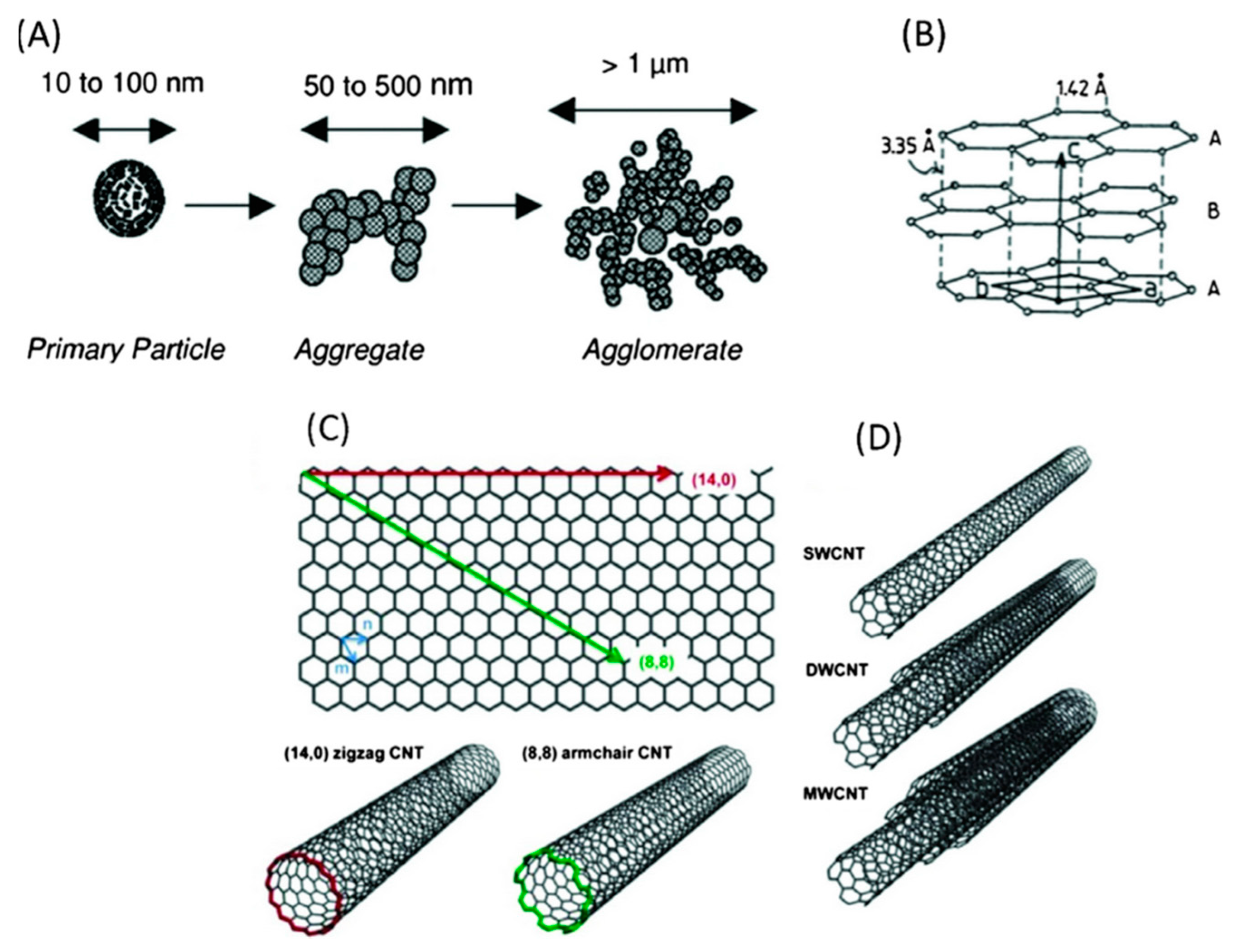
3.2.1. Electrical Behaviour of CNT-Filled Polymer: Theory of Statistic Percolation

3.2.2. Bucky Paper as a Strain Sensing Element
3.2.3. CNT Dispersed in a Matrix as a Sensing Element
Sensing with a CNT Nanocomposite Matrix
Sensing with a Patch of CNT Nanocomposites
3.2.4. CNT Coated Reinforcing Fibres as a Sensing Element
3.2.5. Self-Sensing Materials Based on Hybrid Fillers
4. Conclusions
References
- Schubel, P.J.; Crossley, R.J.; Boateng, E.K.G.; Hutchinson, J.R. Review of structural health and cure monitoring techniques for large wind turbine blades. Renew. Energy 2013, 51, 113–123.
- Balageas, D.; Fritzen, C.-P.; Güemes, A. Structural Health Monitoring; ISTE: Newport Beach, CA, USA, 2006; ISBN 978-1-905209-01-9.
- Huston, D. Structural Sensing, Health Monitoring, and Performance Evaluation (Series in Sensors); CRC Press: Boca Raton, FL, USA, 2011; ISBN 9781420012354.
- Farrar, C.R.; Worden, K. An introduction to structural health monitoring. Philos. Trans. R. Soc. A Math. Phys. Eng. Sci. 2007, 365, 303–315.
- Castro-Santos, L.; Diaz-Casas, V. Green Energy and Technology. In Floating Offshore Wind Farms; Castro-Santos, L., Diaz-Casas, V., Eds.; Springer International Publishing: Cham, Germany, 2016; ISBN 978-3-319-27970-1.
- Mcgugan, M.; Ostachowicz, W.; Schröder-Hinrichs, J.-U.; Luczak, M. Mare-Wint; Ostachowicz, W., McGugan, M., Schröder-Hinrichs, J.-U., Luczak, M., Eds.; Springer International Publishing: Cham, Germany, 2016; ISBN 978-3-319-39094-9.
- Sørensen, B.F.; Jørgensen, E.; Debel, C.P.; Jensen, F.M.; Jensen, H.M.; Jacobsen, T.K.; Halling, K.M. Improved Design of Large Wind Turbine Blade of Fibre Composites Based on Studies of Scale Effects (Phase 1)—Summary Report; Risø-R-139: Roskilde, Denmark, 2004; Volume 1390, ISBN 87-550-3176-5/87-550-3177-3.
- Chen, X.; Zhao, X.; Xu, J. Revisiting the structural collapse of a 52.3 m composite wind turbine blade in a full-scale bending test. Wind Energy 2017, 20, 1111–1127.
- Dransfield, K.; Baillie, C.; Mai, Y.-W. Improving the delamination resistance of CFRP by stitching—a review. Compos. Sci. Technol. 1994, 50, 305–317.
- Takoutsing, P.; Wamkeue, R.; Ouhrouche, M.; Slaoui-Hasnaoui, F.; Tameghe, T.; Ekemb, G. Wind turbine condition monitoring: State-of-the-art review, new trends, and future challenges. Energies 2014, 7, 2595–2630.
- Cooperman, A.; Martinez, M. Load monitoring for active control of wind turbines. Renew. Sustain. Energy Rev. 2015, 41, 189–201.
- Hameed, Z.; Hong, Y.S.; Cho, Y.M.; Ahn, S.H.; Song, C.K. Condition monitoring and fault detection of wind turbines and related algorithms: A review. Renew. Sustain. Energy Rev. 2009, 13, 1–39.
- Hoffmann, K. An Introduction to Stress Analysis and Transducer Design using Strain Gauges. Academia 2012, 127–133.
- Nanolike, Monitor Your Industrial Assets. Available online: http://www.nanolike.com/ (accessed on 25 November 2021).
- Dharap, P.; Li, Z.; Nagarajaiah, S.; Barrera, E.V. Nanotube film based on single-wall carbon nanotubes for strain sensing. Nanotechnology 2004, 15, 379–382.
- Eisler, P. Electric Resistance Devices. US Patent US2441960A, 1952. Available online: https://patents.google.com/patent/US2441960A/en (accessed on 25 November 2021).
- Rs Components. Available online: http://fr.rs-online.com/web/c/automatisme-et-controle-de-process/capteurs-et-transducteurs/jauges-de-contraintes/ (accessed on 25 November 2021).
- Majumder, M.; Gangopadhyay, T.K.; Chakraborty, A.K.; Dasgupta, K.; Bhattacharya, D.K. Fibre Bragg gratings in structural health monitoring-Present status and applications. Sens. Actuators A Phys. 2008, 147, 150–164.
- Li, H.-N.; Li, D.-S.; Song, G.-B. Recent applications of fiber optic sensors to health monitoring in civil engineering. Eng. Struct. 2004, 26, 1647–1657.
- Ramakrishnan, M.; Rajan, G.; Semenova, Y.; Farrell, G. Overview of fiber optic sensor technologies for strain/temperature sensing applications in composite materials. Sensors 2016, 16, 99.
- Takeda, N. Characterization of microscopic damage in composite laminates and real-time monitoring by embedded optical fiber sensors. Int. J. Fatigue 2002, 24, 281–289.
- Takeda, N.; Okabe, Y.; Kuwahara, J.; Kojima, S.; Ogisu, T. Development of smart composite structures with small-diameter fiber Bragg grating sensors for damage detection: Quantitative evaluation of delamination length in CFRP laminates using Lamb wave sensing. Compos. Sci. Technol. 2005, 65, 2575–2587.
- Li, C.; Ning, T.; Li, J.; Pei, L.; Zhang, C.; Zhang, C.; Lin, H.; Wen, X. Simultaneous measurement of refractive index, strain, and temperature based on a four-core fiber combined with a fiber Bragg grating. Opt. Laser Technol. 2017, 90, 179–184.
- Mieloszyk, M.; Ostachowicz, W. Moisture contamination detection in adhesive bond using embedded FBG sensors. Mech. Syst. Signal Process. 2017, 84, 1–14.
- Mieloszyk, M.; Ostachowicz, W. An application of Structural Health Monitoring system based on FBG sensors to offshore wind turbine support structure model. Mar. Struct. 2017, 51, 65–86.
- Kinet, D.; Mégret, P.; Goossen, K.; Qiu, L.; Heider, D.; Caucheteur, C. Fiber Bragg grating sensors toward structural health monitoring in composite materials: Challenges and solutions. Sensors 2014, 14, 7394–7419.
- Huang, C.Y.; Trask, R.S.; Bond, I.P. Characterization and analysis of carbon fibre-reinforced polymer composite laminates with embedded circular vasculature. J. R. Soc. Interface 2010, 7, 1229–1241.
- Luyckx, G.; Voet, E.; Lammens, N.; Degrieck, J. Strain measurements of composite laminates with embedded fibre Bragg gratings: Criticism and opportunities for research. Sensors 2010, 11, 384–408.
- Yang, R.; He, Y.; Zhang, H. Progress and trends in non-destructive testing and evaluation for wind turbine composite blade. Renew. Sustain. Energy Rev. 2016, 60, 1225–1250.
- Juengert, A. Damage Detection in Wind Turbine Blades using two Different Acoustic Techniques. E-J. Nondestruct. Test. 2008, 1–10. Available online: https://www.ndt.net/article/v13n12/juengert.pdf (accessed on 25 November 2021).
- García Márquez, F.P.; Tobias, A.M.; Pinar Pérez, J.M.; Papaelias, M. Condition monitoring of wind turbines: Techniques and methods. Renew. Energy 2012, 46, 169–178.
- Beganovic, N.; Söffker, D. Structural health management utilization for lifetime prognosis and advanced control strategy deployment of wind turbines: An overview and outlook concerning actual methods, tools, and obtained results. Renew. Sustain. Energy Rev. 2016, 64, 68–83.
- Ciang, C.C.; Lee, J.-R.; Bang, H.-J. Structural health monitoring for a wind turbine system: A review of damage detection methods. Meas. Sci. Technol. 2008, 19, 122001.
- Signaltech, Capteurs d’émission Acoustique. Available online: http://www.signaltech.fr/capteurs/emisacoust.html (accessed on 25 November 2021).
- Juengert, A.; Grosse, C.U. Inspection techniques for wind turbine blades using ultrasound and sound waves. In Proceedings of the NDTCE’09, Non-Destructive Testing in Civil Engineering, Nantes, France, 30 June–3 July 2009.
- John, W.N. Method and Apparatus for Monitoring Wind Turbine Blades during Operation. 2013. Available online: https://patents.google.com/patent/US9194843B2/en (accessed on 25 November 2021).
- John, W.N. Nondestructive Testing of Wind Turbine Blades from the Ground during Operation. 2014. Available online: https://patentimages.storage.googleapis.com/09/64/e0/226b5cebac2bb6/EP2984337B1.pdf (accessed on 25 November 2021).
- Frey, A.; Roark, F.; Gonzalez, M. Early Detection of Wind Turbine Degradation Using Acoustical Monitoring. 2013. Available online: https://patentimages.storage.googleapis.com/2c/49/e6/83c174d186ad4d/CA2891326A1.pdf (accessed on 25 November 2021).
- Method and Apparatus for Monitoring Wind Turbine Blades during Operation. US Patent US2014260634A1, 2014. Available online: https://patents.google.com/patent/US20140260634?oq=2014260634A1 (accessed on 25 November 2021).
- Raišutis, R.; Jasi, E.; Šliteris, R.; Vladišauskas, A.; Jasiūnienė, E.; Šliteris, R.; Vladišauskas, A. The review of non-destructive testing techniques suitable for inspection of the wind turbine blades. Ultragarsas 2008, 63, 26–30.
- Giurgiutiu, V. 7.19 Smart Materials and Health Monitoring of Composites. In Comprehensive Composite Materials II; Beaumont, P.W.R., Zweben, C.H., Eds.; Elsevier: Amsterdam, The Netherlands, 2018; pp. 364–381. ISBN 9780128035818.
- Wind Turbine Blade with Strain Sensing Means, Wind Turbine Block Sensor Unit and Uses Hereof. WO Patent WO2008101496A3, 2011. Available online: https://patents.google.com/patent/WO2008101496A3/en (accessed on 25 November 2021).
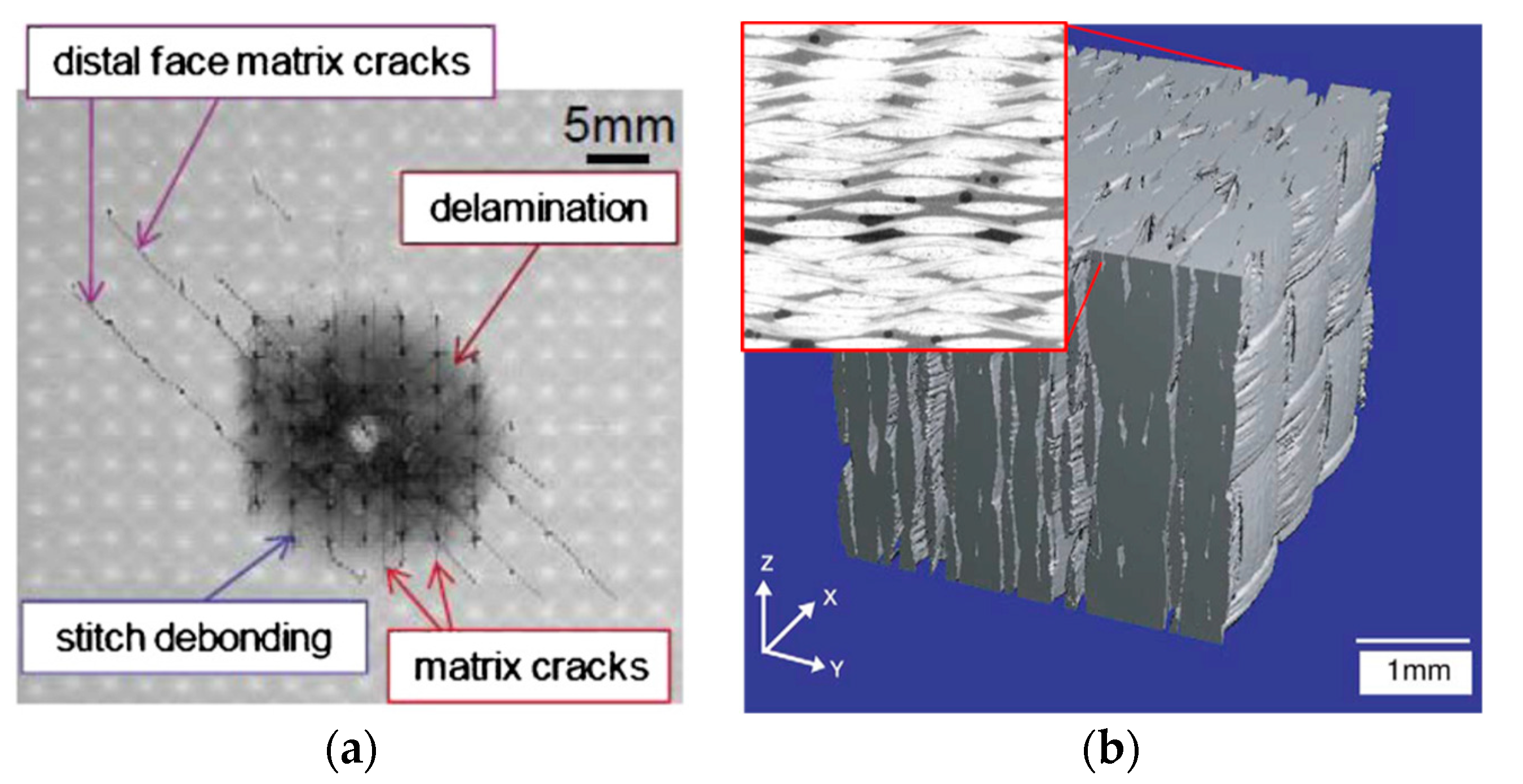
- Tan, K.T.; Watanabe, N.; Iwahori, Y. X-ray radiography and micro-computed tomography examination of damage characteristics in stitched composites subjected to impact loading. Compos. B Eng. 2011, 42, 874–884.
- Schell, J.S.U.; Renggli, M.; van Lenthe, G.H.; Müller, R.; Ermanni, P. Micro-computed tomography determination of glass fibre reinforced polymer meso-structure. Compos. Sci. Technol. 2006, 66, 2016–2022.
- Hofer, B. Fibre optic damage detection in composite structures. Composites 1987, 18, 309–316.
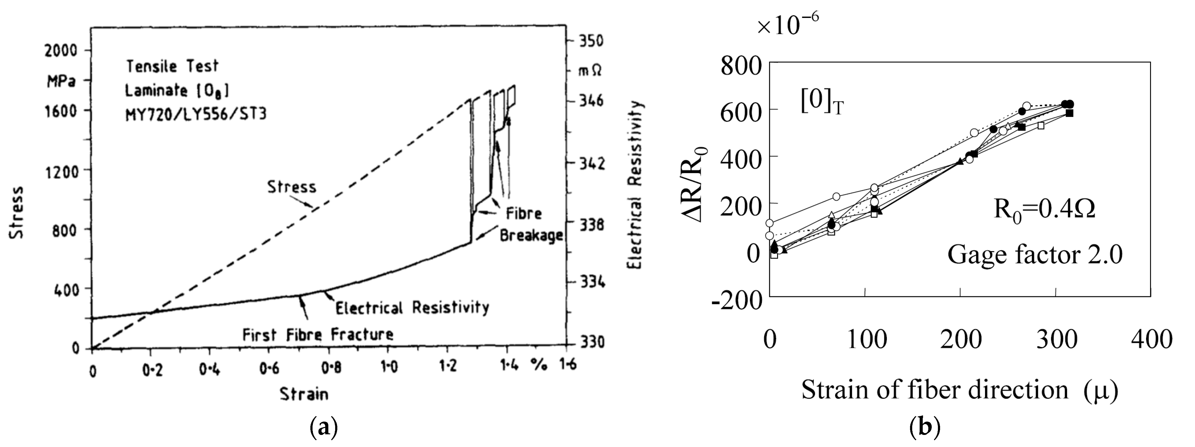
- Schulte, K.; Baron, C. Load and failure analyses of CFRP laminates by means of electrical resistivity measurements. Compos. Sci. Technol. 1989, 36, 63–76.
- Wang, X.; Chung, D.D.L. Short-carbon-fiber-reinforced epoxy as a piezoresistive strain sensor. Smart Mater. Struct. 1995, 4, 363–367.
- Todoroki, A.; Yoshida, J. Electrical resistance change of unidirectional CFRP due to applied load. JSME Int. J. Ser. A 2004, 47, 357–364.
- Todoroki, A.; Ueda, M.; Hirano, Y. Strain and damage monitoring of CFRP laminates by means of electrical resistance measurement. J. Solid Mech. Mater. Eng. 2007, 1, 947–974.
- Thostenson, E.T.; Ren, Z.; Chou, T.W. Advances in the science and technology of carbon nanotubes and their composites: A review. Compos. Sci. Technol. 2001, 61, 1899–1912.
- Kim, P.; Shi, L.; Majumdar, A.; McEuen, P.L. Thermal Transport Measurements of Individual Multiwalled Nanotubes. Phys. Rev. Lett. 2001, 87, 215502.
- Asai, S.; Sumita, M. Effect of interfacial energy and viscosity on percolation time of carbon black-filled poly(methyl methacrylate). J. Macromol. Sci. Part B 1995, 34, 283–294.
- Yao, Z.; Kane, C.L.; Dekker, C. High-Field Electrical Transport in Single-Wall Carbon Nanotubes. Phys. Rev. Lett. 2000, 84, 2941–2944.
- Ebbesen, T.W.; Lezec, H.J.; Hiura, H.; Bennett, J.W.; Ghaemi, H.F.; Thio, T. Electrical conductivity of individual carbon nanotubes. Nature 1996, 382, 54–56.
- Treacy, M.M.J.; Ebbesen, T.W.; Gibson, J.M. Exceptionally high Young’s modulus observed for individual carbon nanotubes. Nature 1996, 381, 678–680.
- Feller, J.F.; Kumar, B.; Castro, M. Conductive biopolymer nanocomposites for sensors. In Nanocomposites with Biodegradable Polymers: Synthesis, Properties & Future Perspectives; Mital, V., Ed.; Oxford University Press: Oxford, UK, 2011; pp. 368–399. ISBN 978-0-19-958192-4.
- Martin, C.A.; Sandler, J.K.W.; Shaffer, M.S.P.; Schwarz, M.K.; Bauhofer, W.; Schulte, K.; Windle, A.H. Formation of percolating networks in multi-wall carbon-nanotube–epoxy composites. Compos. Sci. Technol. 2004, 64, 2309–2316.
- Ambrosetti, G.; Grimaldi, C.; Balberg, I.; Maeder, T.; Danani, A.; Ryser, P. Solution of the tunneling-percolation problem in the nanocomposite regime. Phys. Rev. B 2010, 81, 155434.
- Stauffer, D.; Aharony, A. Introduction to Percolation Theory; Taylor & Francis: Abingdon-on-Thame, UK, 1994; Volume 6, ISBN 1420074792.
- Feller, J.F.; Castro, M.; Kumar, B. Polymer-carbon nanotube conductive nanocomposites for sensing. In Polymer-Carbon Nanotube Composites: Preparation, Properties & Applications; McNally, T., Pötschke, P., Eds.; Woodhead Publishing Limited: Swaston, UK, 2011; pp. 760–803. ISBN 9781845697617.
- Li, Z.; Dharap, P.; Nagarajaiah, S.; Barrera, E.V.; Kim, J.D. Carbon Nanotube Film Sensors. Adv. Mater. 2004, 16, 640–643.
- Barrera, E.V.; Nagarajaiah, S.; Dharap, P.; Zhiling, L.; Kim, J.D. Smart Materials: Strain Sensing and Stress Determination by Means of Nanotube Sensing Systems, Composites, and Devices. 2010. Available online: https://patentimages.storage.googleapis.com/86/cd/4e/901c7b0b2dc158/US7730547.pdf (accessed on 25 November 2021).
- Liu, L.; Wu, J.; Zhou, Y. Enhanced delamination initiation stress and monitoring sensitivity of quasi-isotropic laminates under in-plane tension by interleaving with CNT buckypaper. Compos. Part A Appl. Sci. Manuf. 2016, 89, 10–17.
- Fiedler, B.; Gojny, F.H.; Wichmann, M.H.G.; Bauhofer, W.; Schulte, K. Can carbon nanotubes be used to sense damage in composites? Ann. Chim. Sci. Matériaux 2004, 29, 81–94.
- Li, C.; Thostenson, E.T.; Chou, T.W. Dominant role of tunneling resistance in the electrical conductivity of carbon nanotube–based composites. Appl. Phys. Lett. 2007, 91, 223114.
- Thostenson, E.T.; Chou, T.W. Processing-structure-multi-functional property relationship in carbon nanotube/epoxy composites. Carbon 2006, 44, 3022–3029.
- Gao, L.; Chou, T.W.; Thostenson, E.T.; Zhang, Z.; Coulaud, M. In situ sensing of impact damage in epoxy/glass fiber composites using percolating carbon nanotube networks. Carbon 2011, 49, 3382–3385.
- Gao, L.; Chou, T.W.; Thostenson, E.T.; Zhang, Z. A comparative study of damage sensing in fiber composites using uniformly and non-uniformly dispersed carbon nanotubes. Carbon 2010, 48, 3788–3794.
- Li, C.; Chou, T.W. Modeling of damage sensing in fiber composites using carbon nanotube networks. Compos. Sci. Technol. 2008, 68, 3373–3379.
- Ahmed, S.; Doshi, S.; Schumacher, T.; Thostenson, E.T.; McConnell, J. Development of a novel integrated strengthening and sensing methodology for steel structures using CNT-based composites. J. Struct. Eng. 2017, 143, 04016202.
- Thostenson, E.T.; Chou, T.W. Carbon nanotube-based health monitoring of mechanically fastened composite joints. Compos. Sci. Technol. 2008, 68, 2557–2561.
- Thostenson, E.T.; Chou, T.W. Real-time in situ sensing of damage evolution in advanced fiber composites using carbon nanotube networks. Nanotechnology 2008, 19, 215713.
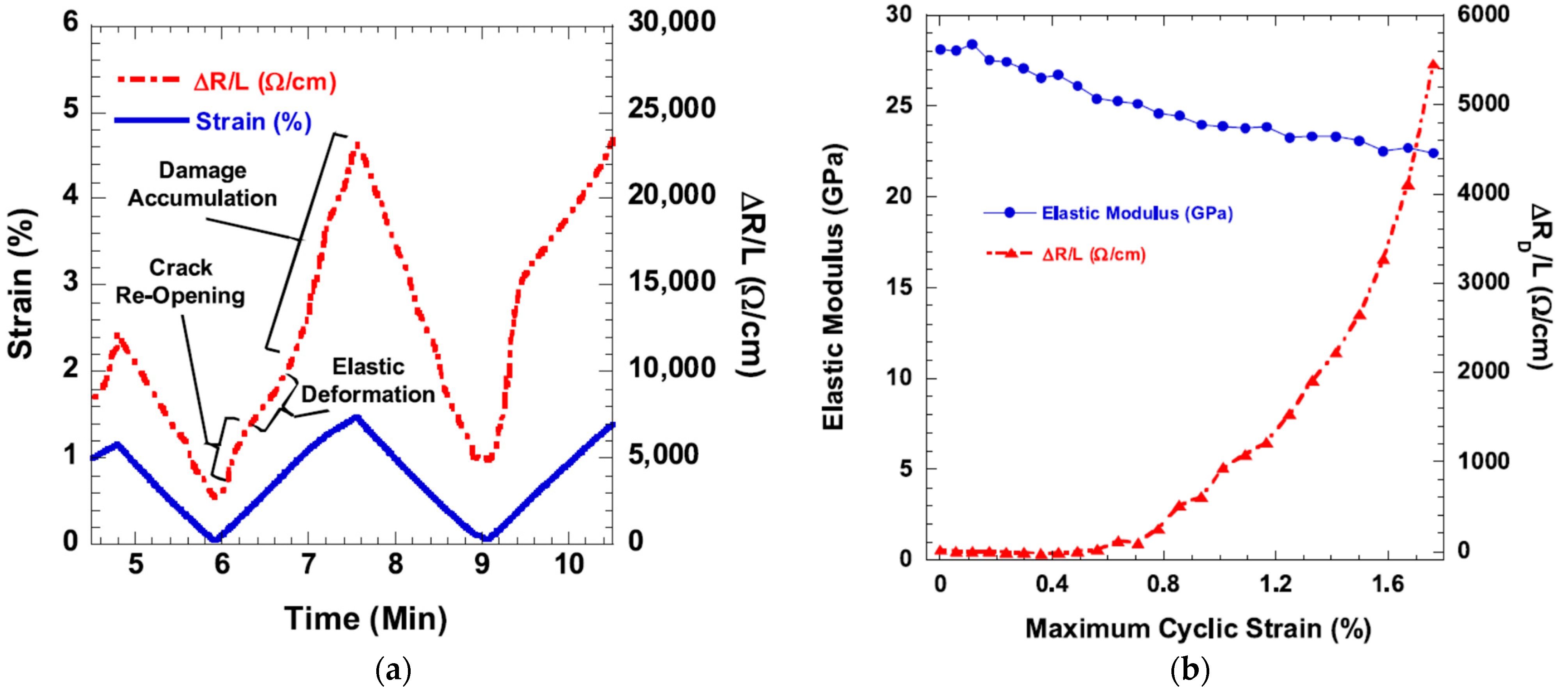
- Gao, L.; Thostenson, E.T.; Zhang, Z.; Chou, T.W. Sensing of damage mechanisms in fiber-reinforced composites under cyclic loading using carbon nanotubes. Adv. Funct. Mater. 2009, 19, 123–130.
- Gao, L.; Thostenson, E.T.; Zhang, Z.; Chou, T.W. Coupled carbon nanotube network and acoustic emission monitoring for sensing of damage development in composites. Carbon 2009, 47, 1381–1388.
- Meeuw, H.; Viets, C.; Liebig, W.V.; Schulte, K.; Fiedler, B. Morphological influence of carbon nanofillers on the piezoresistive response of carbon nanoparticle/epoxy composites under mechanical load. Eur. Polym. J. 2016, 85, 198–210.
- Chiacchiarelli, L.M.; Rallini, M.; Monti, M.; Puglia, D.; Kenny, J.M.; Torre, L. The role of irreversible and reversible phenomena in the piezoresistive behavior of graphene epoxy nanocomposites applied to structural health monitoring. Compos. Sci. Technol. 2013, 80, 73–79.
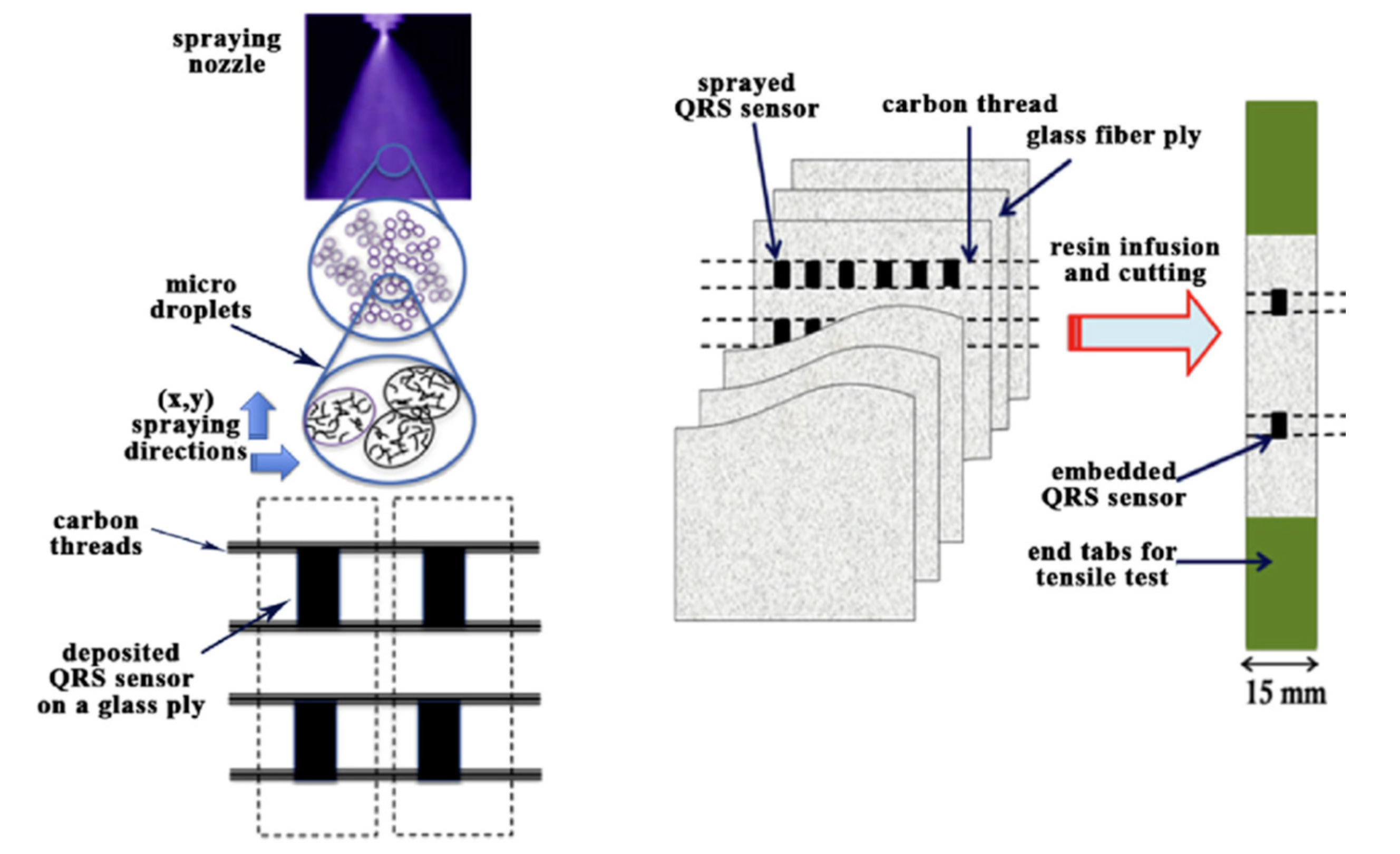
- Robert, C.; Feller, J.F.; Castro, M. Sensing skin for strain monitoring made of PC-CNT conductive polymer nanocomposite sprayed layer by layer. ACS Appl. Mater. Interfaces 2012, 4, 3508–3516.
- Sanli, A.; Müller, C.; Kanoun, O.; Elibol, C.; Wagner, M.F.X. Piezoresistive characterization of multi-walled carbon nanotube-epoxy based flexible strain sensitive films by impedance spectroscopy. Compos. Sci. Technol. 2016, 122, 18–26.
- Kanoun, O.; Benchirouf, A.; Sanli, A.; Bouhamed, A.; Bu, L. Potential of Flexible Carbon Nanotube Films for High Performance Strain and Pressure Sensors. In Nanotechnology for Optics and Sensors; One Central Press: Altrincham, UK, 2014; pp. 148–183.
- Sanli, A.; Benchirouf, A.; Müller, C.; Kanoun, O. Piezoresistive performance characterization of strain sensitive multi-walled carbon nanotube-epoxy nanocomposites. Sens. Actuators A Phys. 2017, 254, 61–68.
- Bouhamed, A.; Müller, C.; Choura, S.; Kanoun, O. Processing and characterization of MWCNTs/epoxy nanocomposites thin films for strain sensing applications. Sens. Actuators A Phys. 2017, 257, 65–72.
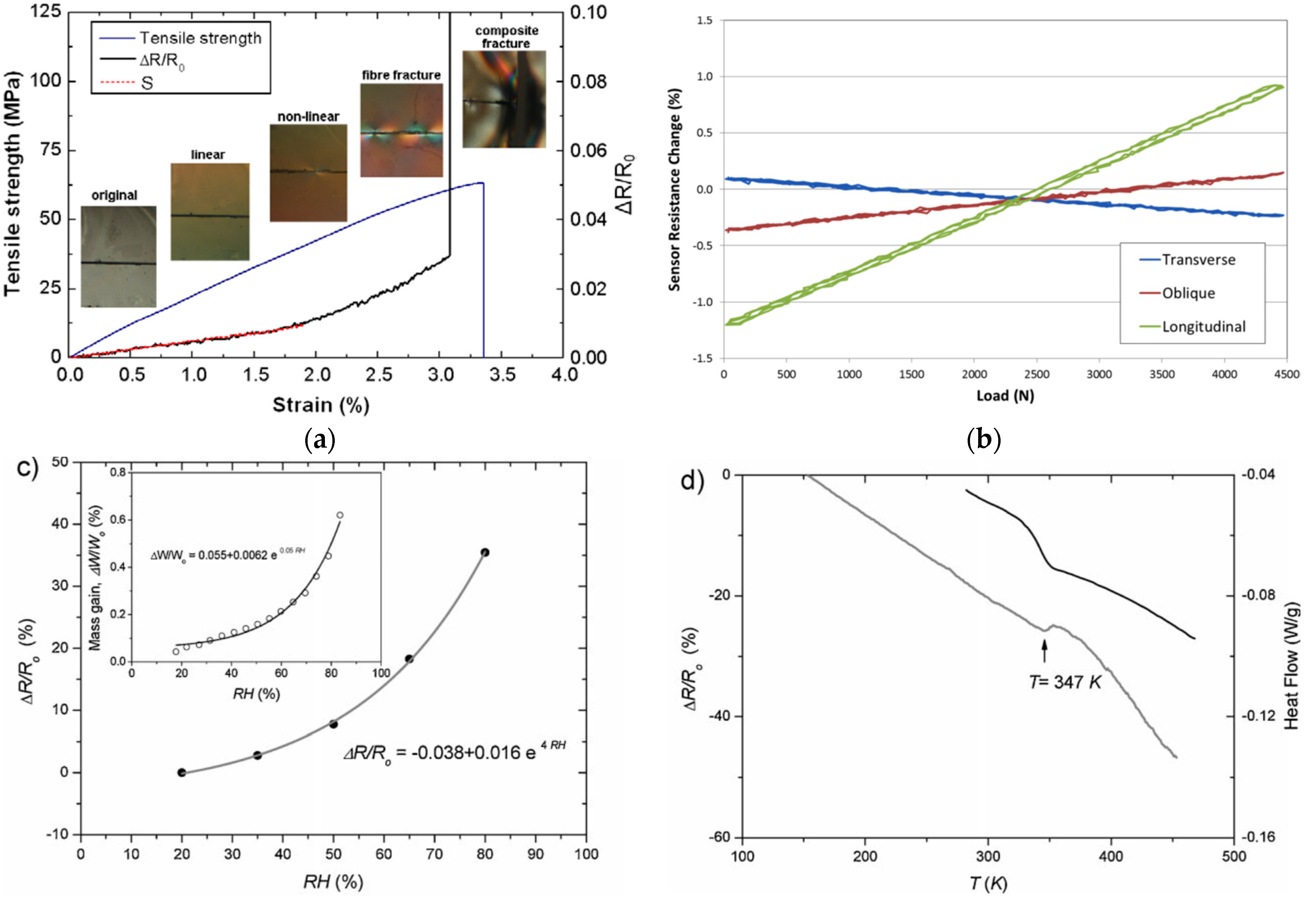
- Nag-Chowdhury, S.; Bellégou, H.; Pillin, I.; Castro, M.; Longrais, P.; Feller, J.F. Non-intrusive health monitoring of infused composites with embedded carbon quantum piezo-resistive sensors. Compos. Sci. Technol. 2016, 123, 286–294.
- Michelis, F.; Bodelot, L.; Bonnassieux, Y.; Lebental, B. Highly reproducible, hysteresis-free, flexible strain sensors by inkjet printing of carbon nanotubes. Carbon 2015, 95, 1020–1026.
- Kaiyan, H.; Weifeng, Y.; Shuying, T.; Haidong, L. A fabrication process to make CNT/EP composite strain sensors. High Perform. Polym. 2018, 30, 224–229.
- Pillin, I.; Castro, M.; Nag-Chowdhury, S.; Feller, J.F. Robustness of carbon nanotube-based sensor to probe composites’ interfacial damage in situ. J. Compos. Mater. 2016, 50, 109–113.
- Zhang, H.; Bilotti, E.; Peijs, T. The use of carbon nanotubes for damage sensing and structural health monitoring in laminated composites: A review. Nanocomposites 2015, 1, 177–194.
- Zhang, J.; Zhuang, R.; Liu, J.; Mäder, E.; Heinrich, G.; Gao, S. Functional interphases with multi-walled carbon nanotubes in glass fibre/epoxy composites. Carbon 2010, 48, 2273–2281.
- Gao, S.L.; Zhuang, R.C.; Zhang, J.; Liu, J.W.; Mäder, E. Glass fibers with carbon nanotube networks as multifunctional sensors. Adv. Funct. Mater. 2010, 20, 1885–1893.
- Siddiqui, N.A.; Li, E.L.; Sham, M.; Zhong, B.; Lin, S.; Mäder, E.; Kim, J. Tensile strength of glass fibres with carbon nanotube—epoxy nanocomposite coating: Effects of CNT morphology and dispersion state. Compos. Part A 2010, 41, 539–548.
- Zhang, J.; Liu, J.; Zhuang, R.; Mäder, E.; Heinrich, G.; Gao, S. Single MWNT-Glass Fiber as Strain Sensor and Switch. Adv. Mater. 2011, 23, 3392–3397.
- Sarkar, P.; Nicholson, P.S. Electrophoretic Deposition (EPD): Mechanisms, Kinetics, and Application to Ceramics. J. Am. Ceram. Soc. 1996, 79, 1987–2002.
- Nguyen, F.N.; Yoshioka, K. Conductive Fiber Reinforced Polymer Composite and Multifunctional Composite. Patent n° TW201443120 (A), 11 October 2017.
- Sebastian, J.; Schehl, N.; Bouchard, M.; Boehle, M.; Li, L.; Lagounov, A.; Lafdi, K. Health monitoring of structural composites with embedded carbon nanotube coated glass fiber sensors. Carbon 2014, 66, 191–200.
- Accorsi, J.V. The Impact of Carbon Black Morphology and Dispersion on the Weatherability of polyethylene. Kautsch. Gummi Kunstst. 2001, 54, 321–326.
- Available online: http://www.angstronmaterials.com (accessed on 25 November 2021).
- Available online: http://www.nanocyl.com (accessed on 25 November 2021).
- Frasca, D.; Schulze, D.; Wachtendorf, V.; Huth, C.; Schartel, B. Multifunctional multilayer graphene/elastomer nanocomposites. Eur. Polym. J. 2015, 71, 99–113.
- Jia, J.; Du, X.; Chen, C.; Sun, X.; Mai, Y.; Kim, J. 3D network graphene interlayer for excellent interlaminar toughness and strength in fiber reinforced composites. Carbon 2015, 95, 978–986.
- Yasmin, A.; Daniel, I.M. Mechanical and thermal properties of graphite platelet/epoxy composites. Polymer 2004, 45, 8211–8219.
- Saleem, H.; Edathil, A.; Ncube, T.; Pokhrel, J.; Khoori, S.; Abraham, A.; Mittal, V. Mechanical and thermal properties of thermoset-graphene nanocomposites. Macromol. Mater. Eng. 2016, 301, 231–259.
- Kumar, P.; Yu, S.; Shahzad, F.; Hong, S.M.; Kim, Y.-H.; Koo, C.M. Ultrahigh electrically and thermally conductive self-aligned graphene/polymer composites using large-area reduced graphene oxides. Carbon 2016, 101, 120–128.
- Debelak, B.; Lafdi, K. Use of exfoliated graphite filler to enhance polymer physical properties. Carbon 2007, 45, 1727–1734.
- Shen, J.T.; Buschhorn, S.; De Hosson, J.T.M.; Schulte, K.; Fiedler, B. Pressure and temperature induced electrical resistance change in nano-carbon/epoxy composites. Compos. Sci. Technol. 2015, 115, 1–8.
- Novák, I.; Krupa, I. Electro-conductive resins filled with graphite for casting applications. Eur. Polym. J. 2004, 40, 1417–1422.
- Moriche, R.; Sánchez, M.; Jiménez-Suárez, A.; Prolongo, S.G.; Ureña, A. Strain monitoring mechanisms of sensors based on the addition of graphene nanoplatelets into an epoxy matrix. Compos. Sci. Technol. 2016, 123, 65–70.
- Wichmann, M.H.G.; Buschhorn, S.T.; Gehrmann, J.; Schulte, K. Piezoresistive response of epoxy composites with carbon nanoparticles under tensile load. Phys. Rev. B 2009, 80, 245437.
- Nanni, F.; Ruscito, G.; Puglia, D.; Terenzi, A.; Kenny, J.M.; Gusmano, G. Effect of carbon black nanoparticle intrinsic properties on the self-monitoring performance of glass fibre reinforced composite rods. Compos. Sci. Technol. 2011, 71, 1–8.
- Nanni, F.; Auricchio, F.; Sarchi, F.; Forte, G.; Gusmano, G. Self-sensing CF-GFRP rods as mechanical reinforcement and sensors of concrete beams. Smart Mater. Struct. 2006, 15, 182–186.
- Nanni, F.; Ruscito, G.; Forte, G.; Gusmano, G. Design, manufacture and testing of self-sensing carbon fibre–glass fibre reinforced polymer rods. Smart Mater. Struct. 2007, 16, 2368–2374.
- Feller, J.F.; Linossier, I. Mechanical and rheological properties of poly(ethylene-co-ethyl acrylate) as a function of carbon black content. Macromol. Symp. 2003, 203, 317–324.
- Droval, G.; Feller, J.F.; Salagnac, P.; Glouannec, P. Rheological properties of conductive polymer composite (CPC) filled with double percolated network of carbon nanoparticles and boron nitride powder. e-Polymers 2009, 9, 1–17.
- Lagrève, C.; Feller, J.F.; Linossier, I.; Levesque, G. Poly(butylene terephthalate)/ poly(ethylene-co-alkyl acrylate)/ carbon black conductive composites: Influence of composition and morphology on electrical properties. Polym. Eng. Sci. 2001, 41, 1124–1132.
- Pillin, I.; Feller, J.F. Influence of carbon-black nanoparticles on poly (butylene terephthalate) fractionated crystallization in bicomponent poly (butylene terephthalate)/poly (ethylene-co-ethyl acrylate) blends. Macromol. Mater. Eng. 2006, 291, 1375–1387.
- Szeluga, U.; Kumanek, B.; Trzebicka, B. Synergy in hybrid polymer/nanocarbon composites: A review. Compos. Part A Appl. Sci. Manuf. 2015, 73, 204–231.

