The growing demands for electrical energy, especially renewable, is boosting the development of wind turbines equipped with longer composite blades. To reduce the maintenance cost of huge composite parts, the structural health monitoring (SHM) is an approach to anticipate and/or follow the structural behaviour along time. Apart from the development of traditional non-destructive testing methods, in order to reduce the use of intrusive instrumentation there is a growing interest for the development of “self-sensing materials”. An interesting route to achieve this, can be to introduce carbon nanofillers such as nanotubes (CNT) in the composite structures, which enables to create systems that are sensitive to both strain and damage.
- composite materials
- structural health monitoring (SHM)
- fibre-reinforced plastics (FRP)
- nano engineered composites
- carbon nanotubes (CNT)
1. Introduction
-
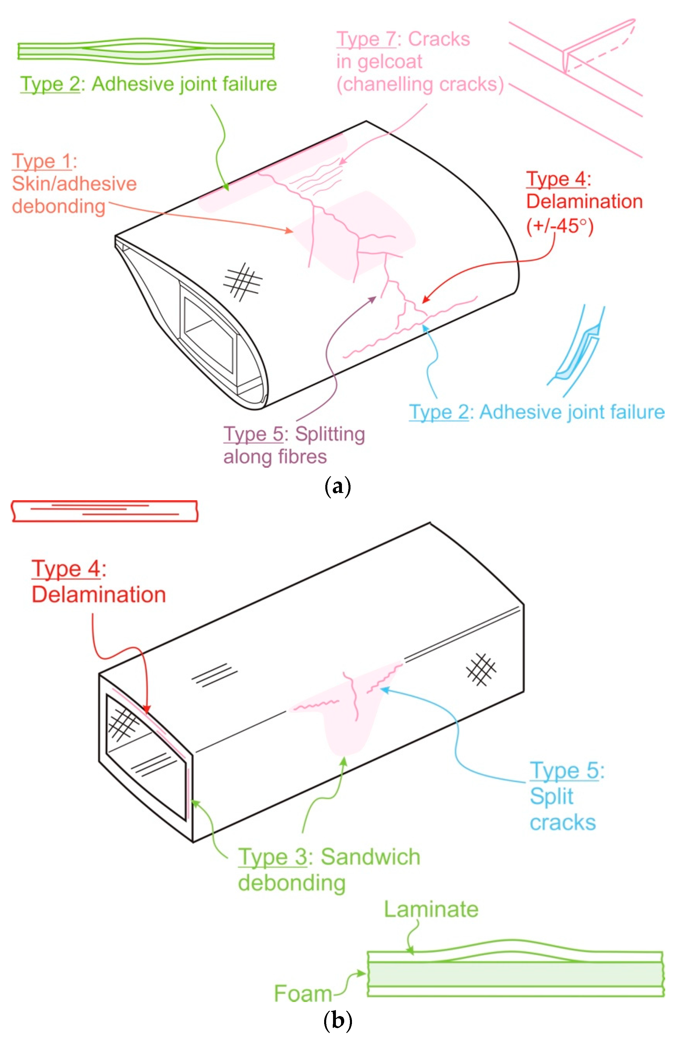
Type 1: Damage formation and growth in the adhesive layer joining skin and main spar flanges (skin/adhesive debonding and/or main spar/adhesive layer debonding),
-
Type 2: Damage formation and growth in the adhesive layer joining the up and downwind skins along leading and/or trailing edges (adhesive joint failure between skins),
-
Type 3: Damage formation and growth at the interface between face and core in sandwich panels in skins and main spar web (sandwich panel face/core debonding),
-
Type 4: Internal damage formation and growth in laminates in skin and/or main spar flanges, under a tensile or compression load (delamination driven by a tensional or a buckling load),
-
Type 5: Splitting and fracture of separate fibres in laminates of the skin and main spar (fibre failure in tension; laminate failure in compression),
-
Type 6: Buckling of the skin due to damage formation and growth in the bond between skin and main spar under compressive load (skin/adhesive debonding induced by buckling, a specific type 1 case),
-
Type 7: Formation and growth of cracks in the gel-coat; debonding of the gelcoat from the skin (gel-coat cracking and gel-coat/skin debonding).
2. Commercially Available Technics Based on Strain & Damage Monitoring
2.1. Monitoring Technics Used in Strain Analysis
2.1.1. Metallic Strain Gauges
2.1.2. Optical Fibres
Several technologies based on optical fibres (OF) already exist, with a predominance of fibre Bragg grating (FBG) or Rayleigh scattering [18]. A FBG sensor is a periodic variation of the refractive index in the fibre’s core (Figure 2). The change of the core refraction index is between 10−5 and 10−3, and the length of a Bragg grating is usually around 10 mm [19]. When an emitted light along the fibre arrives on the sensor, the change of the refraction index induces the creation of a transmitted and a reflected light signal as shown in Figure 2.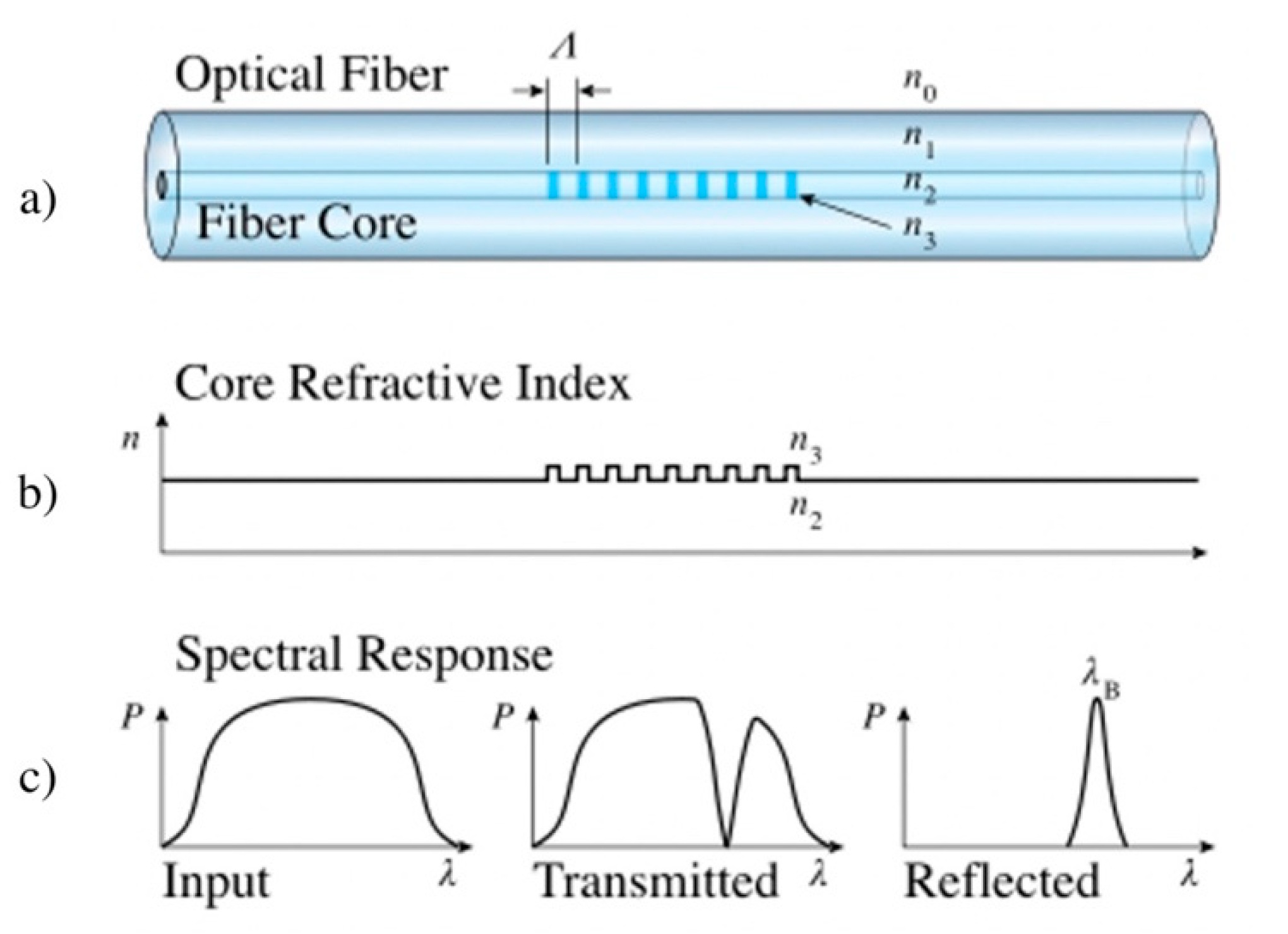
2.2. Monitoring Techniques Used in Failure Analysis
2.2.1. Visual Inspection
2.2.2. Performance Analysis
2.2.3. Acoustic Emission (AE)
2.2.4. Ultrasonic Measurements
Unlike acoustic emission, which is a passive NDE, ultrasonic measurement (US) is an active monitoring technic. In addition to the received signal, an external excitation source is emitted. This signal propagates within the structure, is thus affected by the material which modified its characteristics (change of phase, defect, delamination, interfacial problems...) [33][10][35][40]. The use of ultrasonic waves enables to obtain information on the material’s state. Three main techniques exist, named pulse-echo, thickness, and pitch-catch as illustrated in Figure 4. In echo-pulse mode, the wave is sent orthogonally to the material by a transducer which is attached to the surface. The reflection of the wave allows to obtain information on the various defects (type, depth). In thickness mode, the wave is sent through the thickness of the structure, and the reflected wave enables to collect similar information as that in the pulse-echo mode.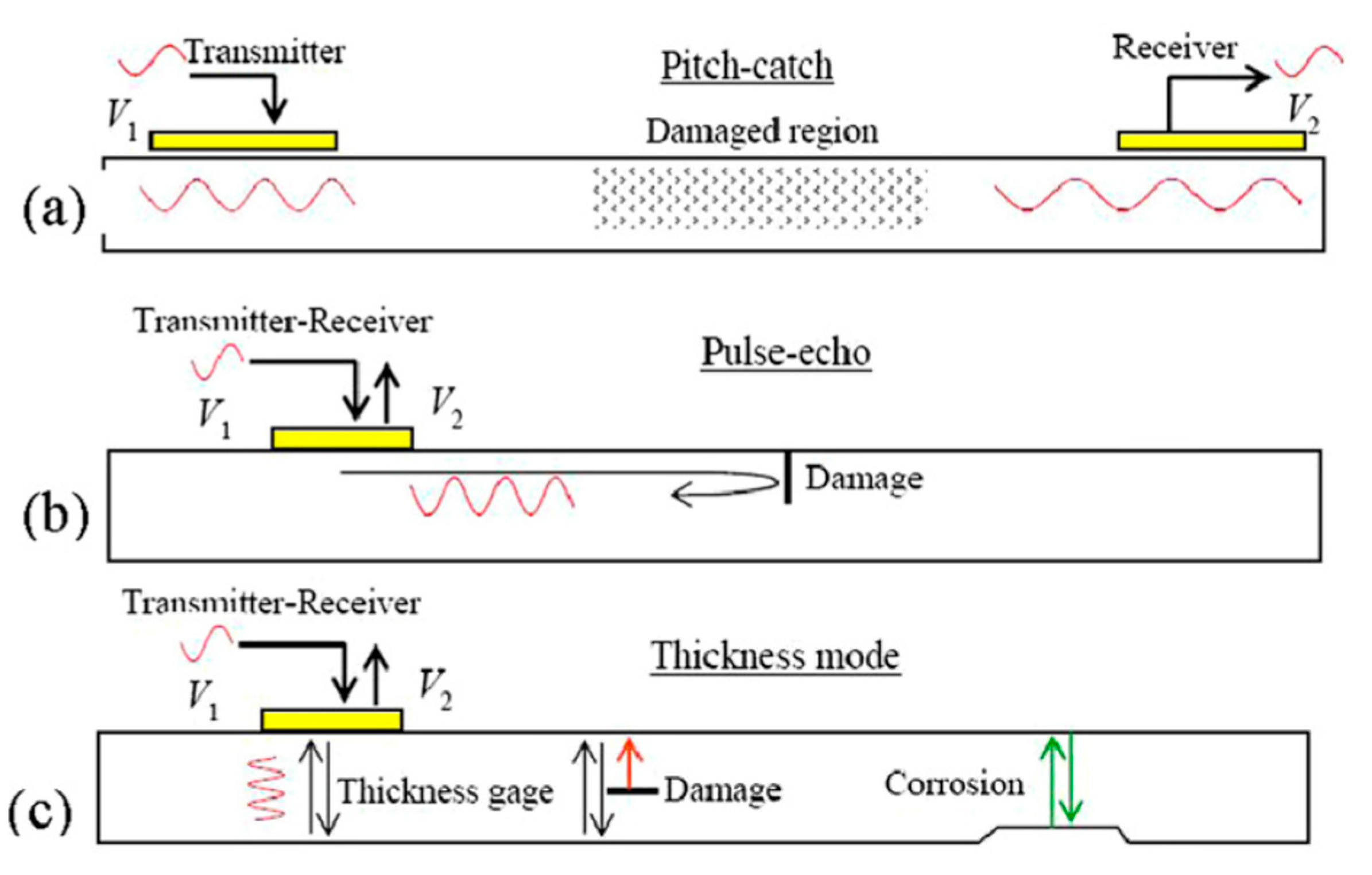
2.2.5. Vibrational Analysis
2.2.6. Radiography
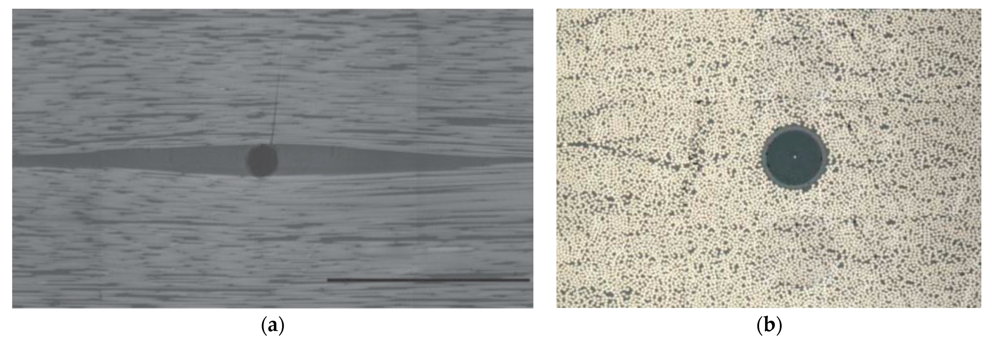
Observation by X-ray in transmission provides an image of the state of the material [31]. Figure 5a, produced by Tan et al. [43], shows an X-ray images of a 6.1 mm thick CFRP laminate after a 6.7 J impact, where different resulting damages have been identified. As shown in Figure 5b with a 3D reconstruction of a GFRP sample, this technique enables to identify the presence of defects such as breaks, delaminations, lacks of adhesive, vacuums, or shifts in the fibres orientation [33][10][40][44]. The detection limit is about 10 μm, and this technique is sensitive to a variation of up to 1–2% of the material thickness. It is also possible to retrieve information on the variation of the materials’ density from the backscattering of X-rays. This technique enables to quickly obtain a state of the structure because the set of images is obtained simultaneously. On the other hand, it is a complicated technique to implement because it requires greater security measures due to the X-rays hazard. It is therefore used to control the quality of the structure after manufacturing.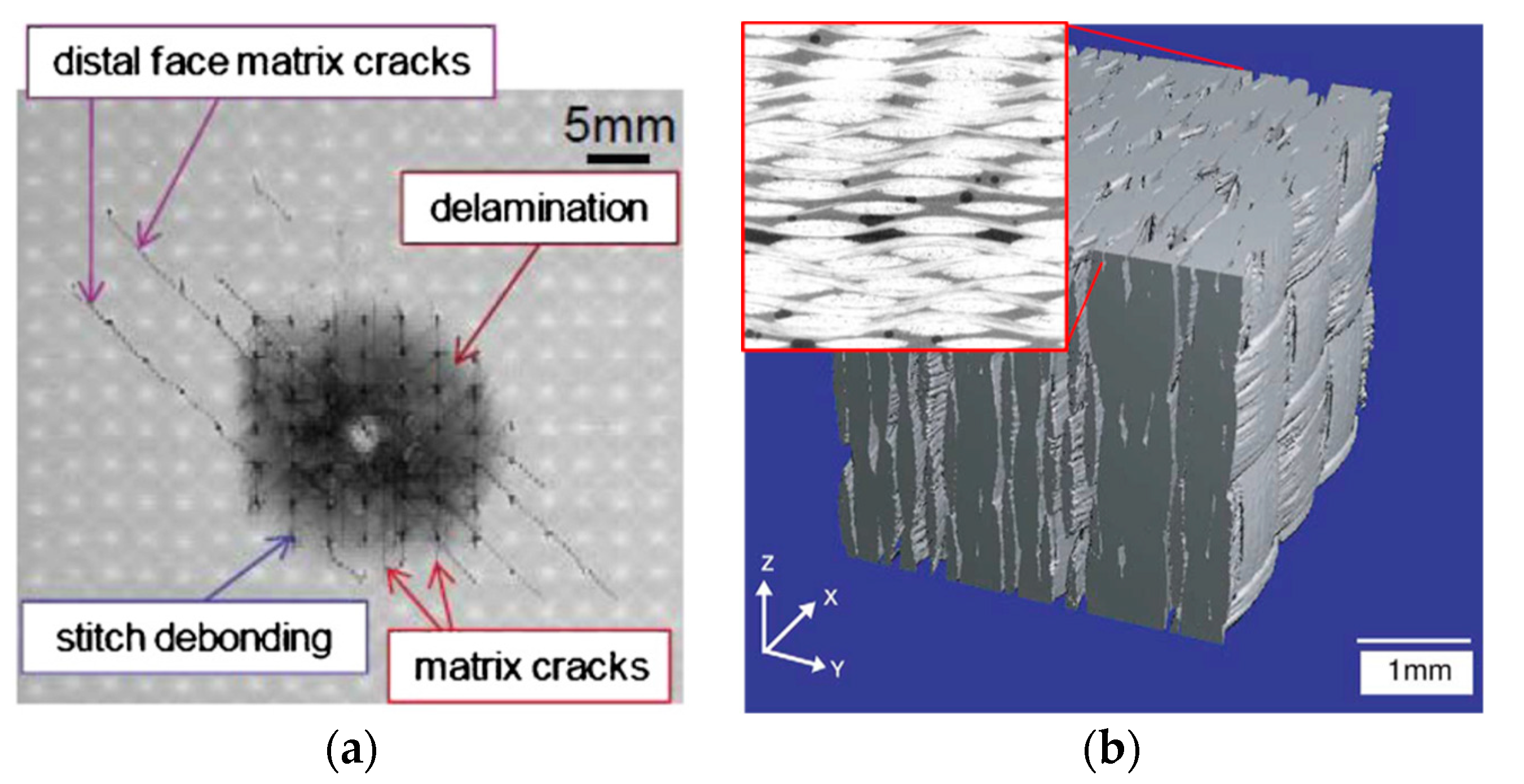
2.2.7. Optical Fibres (OF)
3. Emerging Technics Based on Self-Sensing Thermoset Composites Filled with Carbon Materials
The classical SHM and maintenance technics previously described have shown to be efficient methods for strain and damage detection. Nevertheless, most of them require either an extensive human involvement or expensive procedures. Moreover, they present partial information of the structure since they are only sensitive to strain or damage. Consequently, the combination of complementary technics appears compulsory for a suitable SHM system. To date, the use of optical fibres is the most promising technique, because firstly it can provide, at a laboratory scale, both strain and specific damages, and, secondly, unlike the other technics, the optical fibres could be embedded in the core of composite structures (their detrimental effects on the mechanical properties being acceptable). Nevertheless, their sensitivity remains lower than that of commercial metallic strain gauges, and a substantial equipment is required, as well for the fibres’ deployment as for the in-service use. Consequently, in parallel with the previously mentioned strategies, there has been a growing interest for the development of “self-sensing materials”. Those materials are prone to provide real-time information about themselves or their environment [2].
3.1. Carbon Fibre Reinforced Epoxy (CF-EP) as Self-Sensing Materials
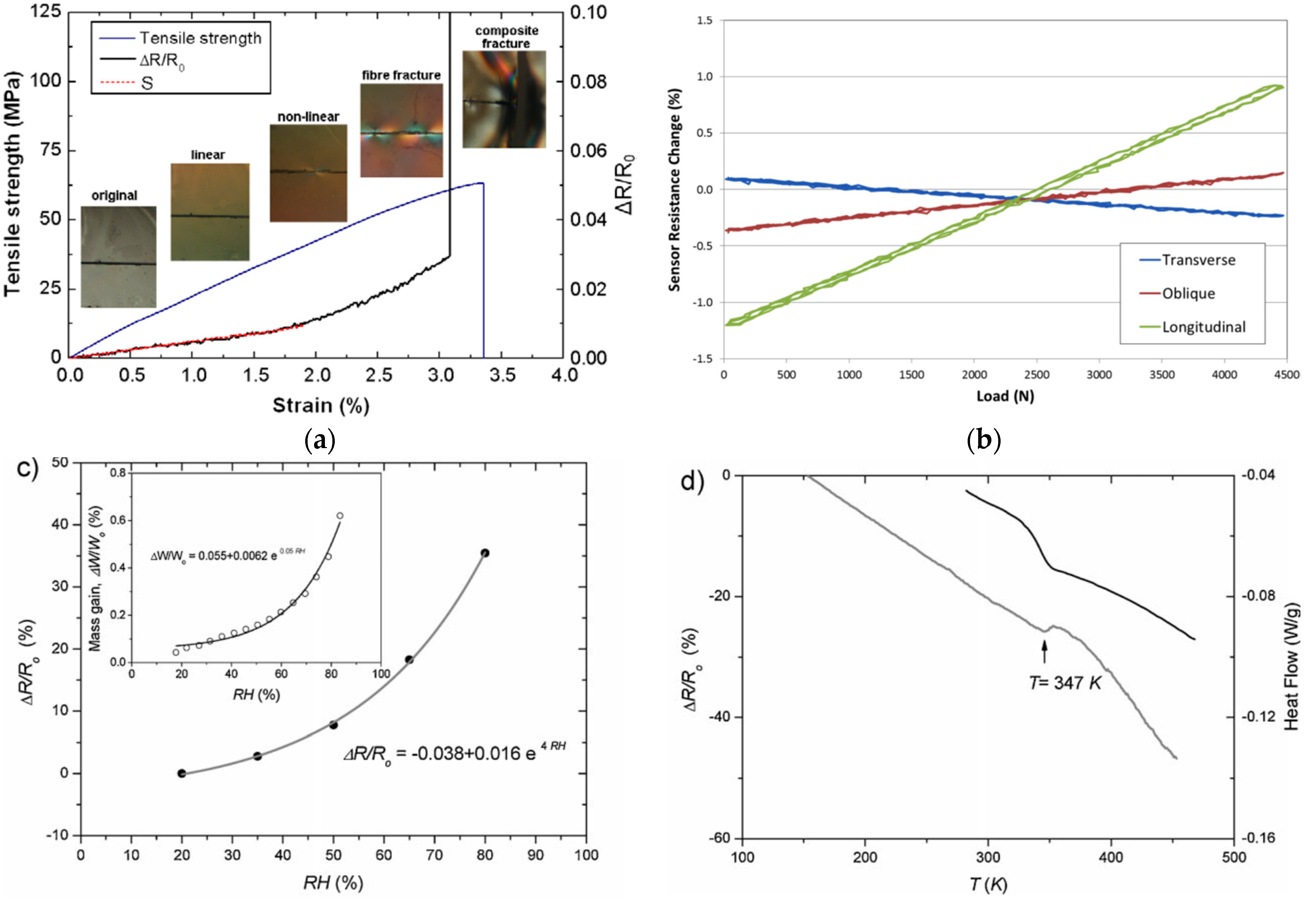
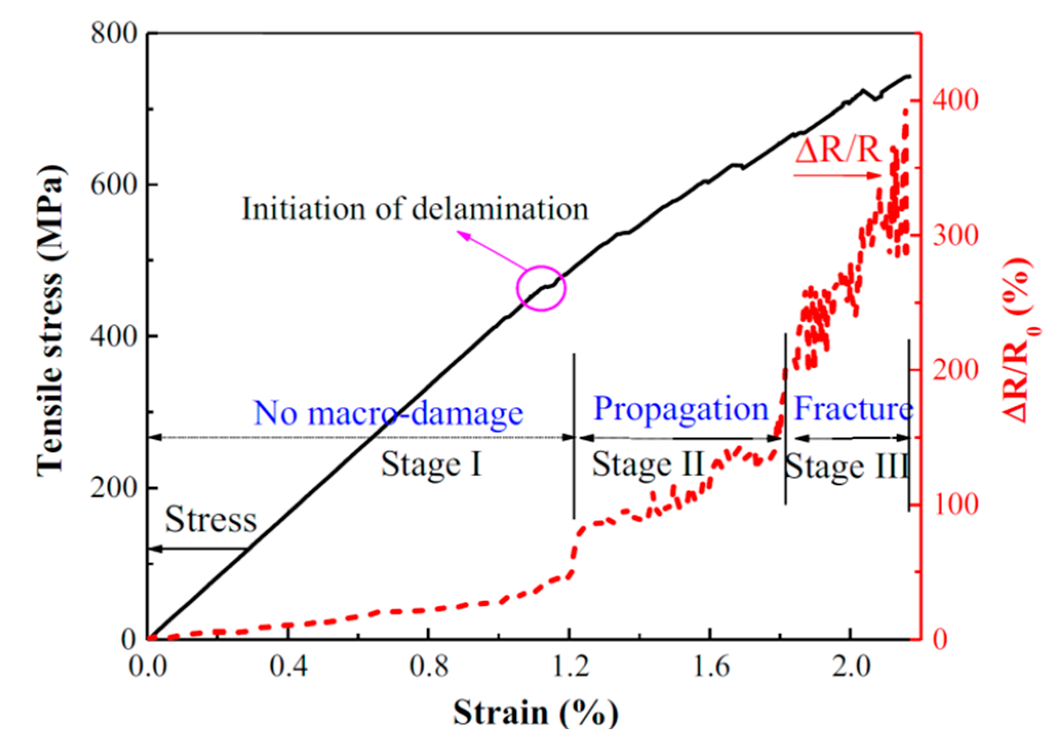
In 1989, Schulte and Baron [46], while studying carbon fibres reinforced epoxy, were the first to report the direct use of carbon fibres’ resistance change as piezo-resistive sensing strategy. As observed in Figure 6a, the change of resistance was linear with the strain until the first fibre fracture at 0.7%, followed by a larger change of resistance and finally infinite resistance at the breakage of the sample. They reported an initial resistivity of 332 Ω·m (2.5 MΩ for a 19 cm long sample), and a 0.6% change of resistance at 1.0% of deformation. Similar results have been reported by Wang et al. [47] with a sample of epoxy reinforced with 5.5 vol.% of short carbon fibres, and Todoroki et al. [48][49] mentioned that they could reach a gauge factor close to 2 with CF-EP samples, as shown in Figure 6b.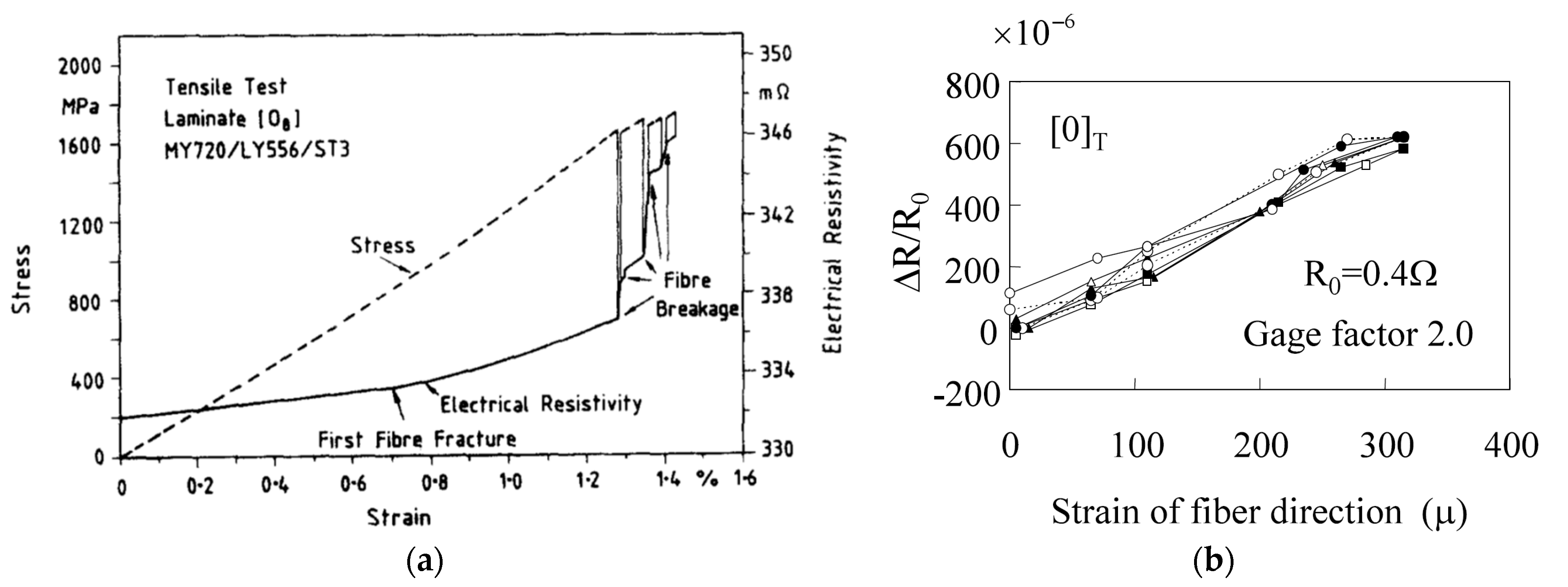
3.2. Carbon Nanoparticles and Their Associated Nanocomposites as Self-Sensing Systems
3.2.1. Electrical Behaviour of CNT-Filled Polymer: Theory of Statistic Percolation
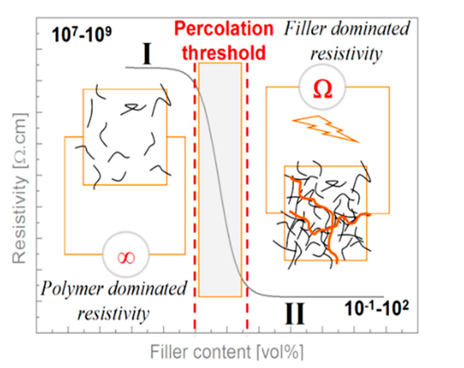
The electrical conductivity of nanocomposites is obtained through the dispersion of conductive fillers into an insulating matrix. Increasing the amount of conductive fillers leads to an insulator-to-conductor transition, as illustrated in Figure 7. At low content of fillers dispersed in a matrix, no conductive pathway can be created inducing an insulating electrical behaviour [56]. When the first conductive pathway appears throughout the material, an insulator-to-conductor transition occurs with a sudden decrease of the material’s resistivity [57][58]. This sharp transition is commonly referred as the percolation threshold. Above the percolation threshold, the matrix conductivity can be described by the Equation [59]: where φ indicates the volume fraction of the conductive filler, φc the volume fraction at the percolation threshold, ρ and ρ0 are the resistivity at φ and for an infinite content of filler respectively, t is the critical exponent comprises between 1.3 and 2.0.
3.2.2. Bucky Paper as a Strain Sensing Element
3.2.3. CNT Dispersed in a Matrix as a Sensing Element
Sensing with a CNT Nanocomposite Matrix
Sensing with a Patch of CNT Nanocomposites
3.2.4. CNT Coated Reinforcing Fibres as a Sensing Element