The growing demands for electrical energy, especially renewable, is boosting the development of wind turbines equipped with longer composite blades. To reduce the maintenance cost of huge composite parts, the structural health monitoring (SHM) is an approach to anticipate and/or follow the structural behaviour along time. Apart from the development of traditional non-destructive testing methods, in order to reduce the use of intrusive instrumentation there is a growing interest for the development of “self-sensing materials”. An interesting route to achieve this, can be to introduce carbon nanofillers such as nanotubes (CNT) in the composite structures, which enables to create systems that are sensitive to both strain and damage.
1. Introduction
Structural Health Monitoring (SHM) system, which would provide clues about the material’s health state, comes out as a very interesting tool
[1][2][3][4]. SHM systems have multiple objectives, such as allowing an optimal use of the structure, decreasing the downtime, and avoiding catastrophic failure. It should also help to replace the scheduled and periodic maintenances by performance-based inspections; as well as to reduce the human involvement for less labour, human errors, and therefore higher reliability. Structural Health Monitoring (SHM) of wind turbine blades is required, because their failure is one of the main reasons for turbine downtimes
[5]. Today’s main causes of damages in blades are identified as follows
[6]: Firstly, the erosion of the leading edge, mainly close to the tip, caused by abrasive airborne particles, and reduces the aerodynamic efficiency. It can also create delamination along the edge. Secondly, the lightning can induce damages and cracks around the impact point. Then, the accumulation of ice on the blade’s surface, due to the combination of climate and temperature conditions, can result in a reduction of the aerodynamic or an increase of the fatigue caused by the additional mass.
Wind turbines have an expected life time of 20 years. The degradation of blades due to fatigue mechanisms is therefore likely to happen before the end of life and requiring reparations after a pertinent diagnosis. The resulting damages proposed by Sørensen et al.
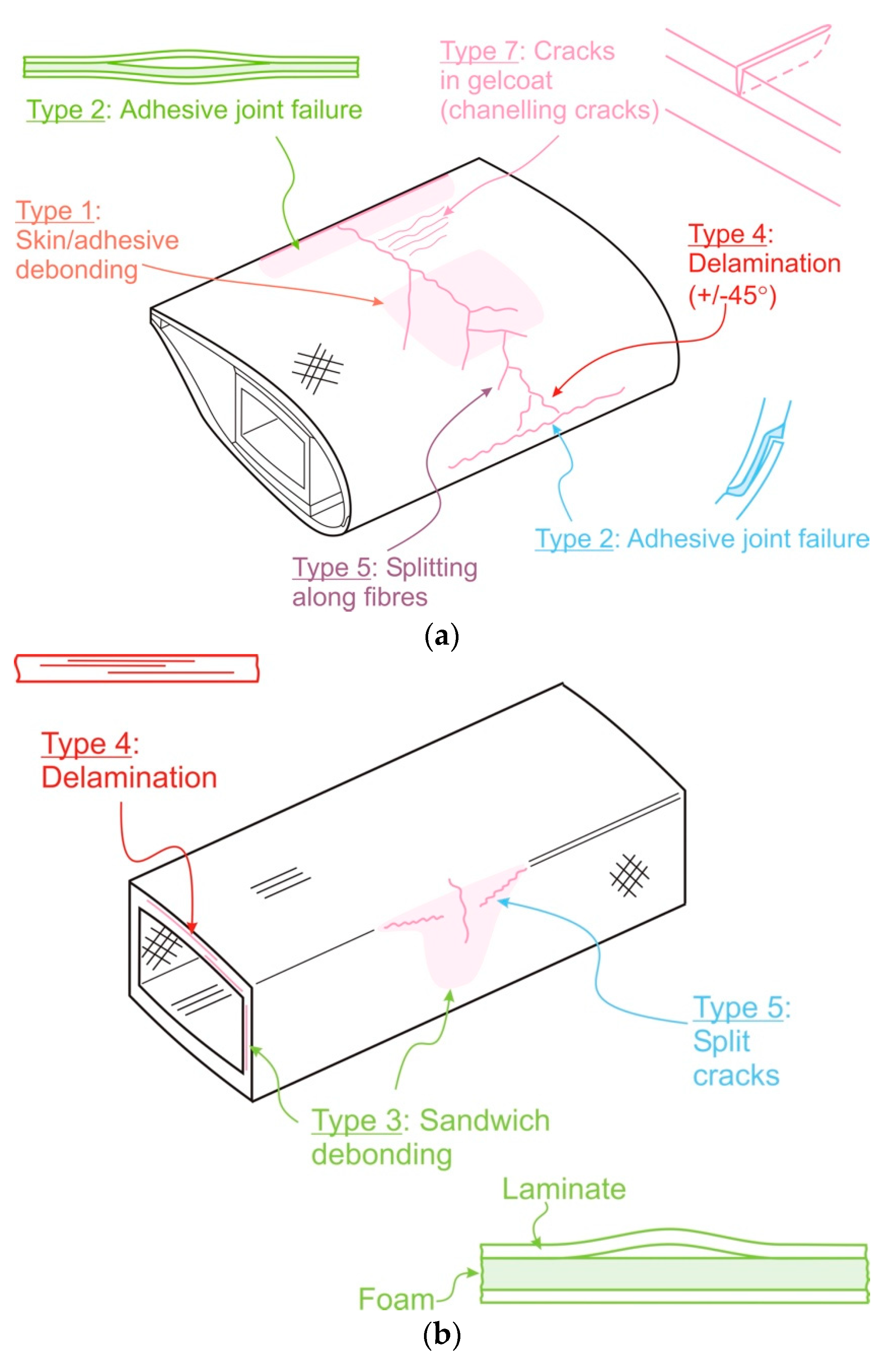
[7] are shown in
Figure 1.
Figure 1. Sketches of the different types of damage that can occur in a wind turbine blade, (
a) by skin-adhesive debonding, (
b) delamination
[7].
The different sketches of damage can be classified in 7 types:
-
Type 1: Damage formation and growth in the adhesive layer joining skin and main spar flanges (skin/adhesive debonding and/or main spar/adhesive layer debonding),
-
Type 2: Damage formation and growth in the adhesive layer joining the up and downwind skins along leading and/or trailing edges (adhesive joint failure between skins),
-
Type 3: Damage formation and growth at the interface between face and core in sandwich panels in skins and main spar web (sandwich panel face/core debonding),
-
Type 4: Internal damage formation and growth in laminates in skin and/or main spar flanges, under a tensile or compression load (delamination driven by a tensional or a buckling load),
-
Type 5: Splitting and fracture of separate fibres in laminates of the skin and main spar (fibre failure in tension; laminate failure in compression),
-
Type 6: Buckling of the skin due to damage formation and growth in the bond between skin and main spar under compressive load (skin/adhesive debonding induced by buckling, a specific type 1 case),
-
Type 7: Formation and growth of cracks in the gel-coat; debonding of the gelcoat from the skin (gel-coat cracking and gel-coat/skin debonding).
Furthermore, off-shore wind turbines are exposed to harsh environmental conditions (humidity, salinity, varying temperature…) and fluctuating load that affect the system’s performance and ultimately provoke a failure. A fault is defined as a significant change in the system parameters beyond
acceptable/allowed limits leading to a decrease of the system performance. Depending on the fault and the related criticality, the required actions may include corrective maintenance intending to restore the system to its previous (undamaged) state or emergency maintenance targeting to avoid failures of components and systems. To avoid the downtime of the structure, as well as localising failures and predicting the remaining life time of blades, the development of SHM techniques is inevitable, keeping in mind, at the same time, its beneficial impact on the operating and maintenance costs. In a laminate composite material, damage initiates and propagates in zones of high-stress concentrations, such as free edges around cut-outs, joints or delamination edges
[6][8][9].
2. Commercially Available Technics Based on Strain & Damage Monitoring
The basic principle of strain gauges is to provide the variation of length of the material on defined zones. The damage undergone by a structure is not directly obtained by the strain gauges. Using the resistance laws of materials (Hooke’s laws), the stress can be calculated from the deformation, where the sensor is located
[1]. The knowledge of the mechanical properties of the material is therefore necessary to use strain gauges. Different types of gauges can be found but their principle is similar: any strain undergone by the gauge is directly converted into an electrical or optical signal as an output. Once a gauge is attached to the structure, its deformation is locally similar to the one encountered by the structure. Thus, the gauge signal recording enables an estimation the structure’s deformation. The existing strain gauges mainly rely on capacitance, inductance or resistance of the sensing element, and on transmitted or reflected signals of optical fibres
[1][10][11][12].
2.1. Monitoring Technics Used in Strain Analysis
2.1.1. Metallic Strain Gauges
The elastic deformation of a metal gauge proportionally modifies the value of its resistance. The sensitivity, or gauge factor (GF), of strain gauges is generally in the order of 2 and the initial resistances can vary from 30 Ω to 3 kΩ. The value of the initial resistance, as well as the gauge factor, is precisely set and controlled. The non-linear characteristic of metal gauge usually starts with strains up to ±15%
[13]. For smaller deformation, there is an emergence of new strain gauges with much higher gauge factors, up to 150
[14]. In general, these sensors are preferably positioned on the surface of the structure, possess limited sensitivity towards direction over a defined area
[15], and have a flat surface allowing an optimised adhesion. Since the patent of the printed circuit for foil strain gauge in 1952 by Paul Eisler
[16] the technic has obviously become mature. It is a precise and affordable technology with a standard deviation of the GF value about 1%
[13], and a price around 10 € per direction of measurement
[17].
2.1.2. Optical Fibres
Several technologies based on optical fibres (OF) already exist, with a predominance of fibre Bragg grating (FBG) or Rayleigh scattering
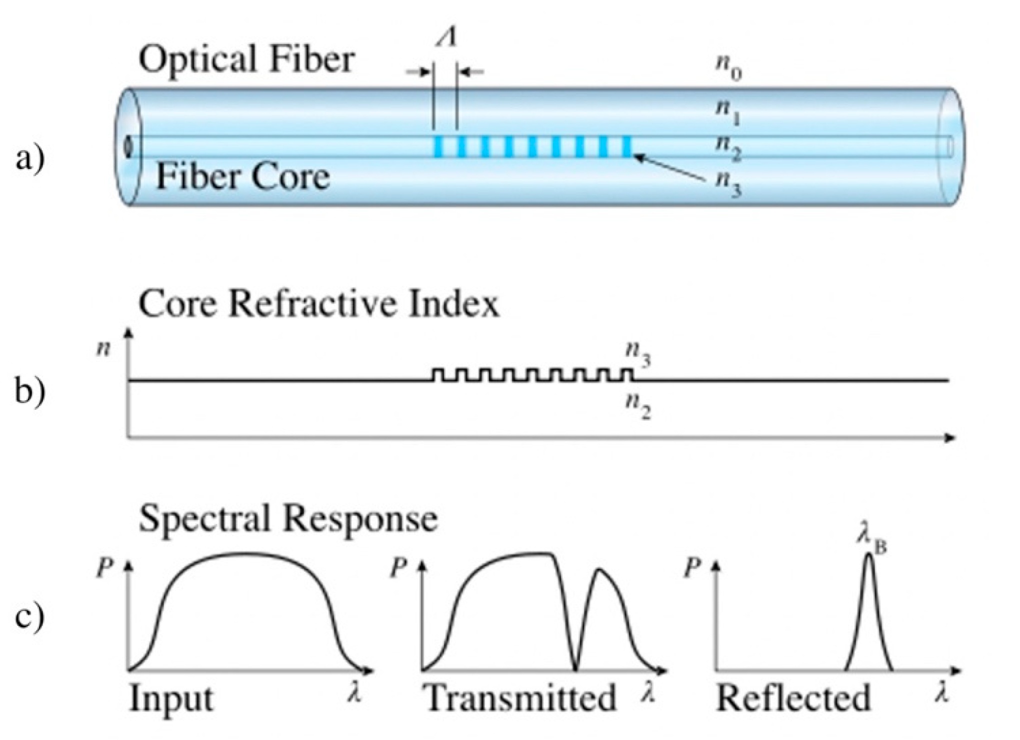
[18]. A FBG sensor is a periodic variation of the refractive index in the fibre’s core (
Figure 2). The change of the core refraction index is between 10
−5 and 10
−3, and the length of a Bragg grating is usually around 10 mm
[19]. When an emitted light along the fibre arrives on the sensor, the change of the refraction index induces the creation of a transmitted and a reflected light signal as shown in
Figure 2.
Figure 2. Principle of a FBG sensor
[20]. (
a) A Fibre Bragg Grating structure with the different refractive index (outer n
0, fibre n
1, core n
0, and grating n
3) and the distance Λ between each grating. (
b) The refractive core index profile. (
c) Illustration of the transmitted and reflected spectral response regarding the input signal.
Any change of the refraction index in the grating modifies the transmitted and reflected signal. External solicitation such as strain, temperature, humidity, vibrations, breaks and delamination can induce a change in the index
[10][19][20][21][22][23][24][25].
Therefore, any local strain or temperature modification can be measured by FBG sensors. Several FBG sensors can be grated along a single OF. A discrete mapping of a structure can therefore be assumed by a unique fibre. In order to discriminate between the strain and the temperature via the wavelength shift, the use of two different optical fibres is requested in practice
[26].
Rayleigh scattering optical fibres have a refractive index which varies along the fibre as a function of the presence of defects or non-homogeneities of the material
[11]. This index variation allows backscattering of different wavelengths at different points of the fibre. The analysis of the backscattered light makes possible to obtain information on the deformation, the changes in temperature, and the undergone flexion at each point along the fibre. Compared to FBG, the strain deformation can be estimated along the complete fibre, thus inducing a larger amount of data.
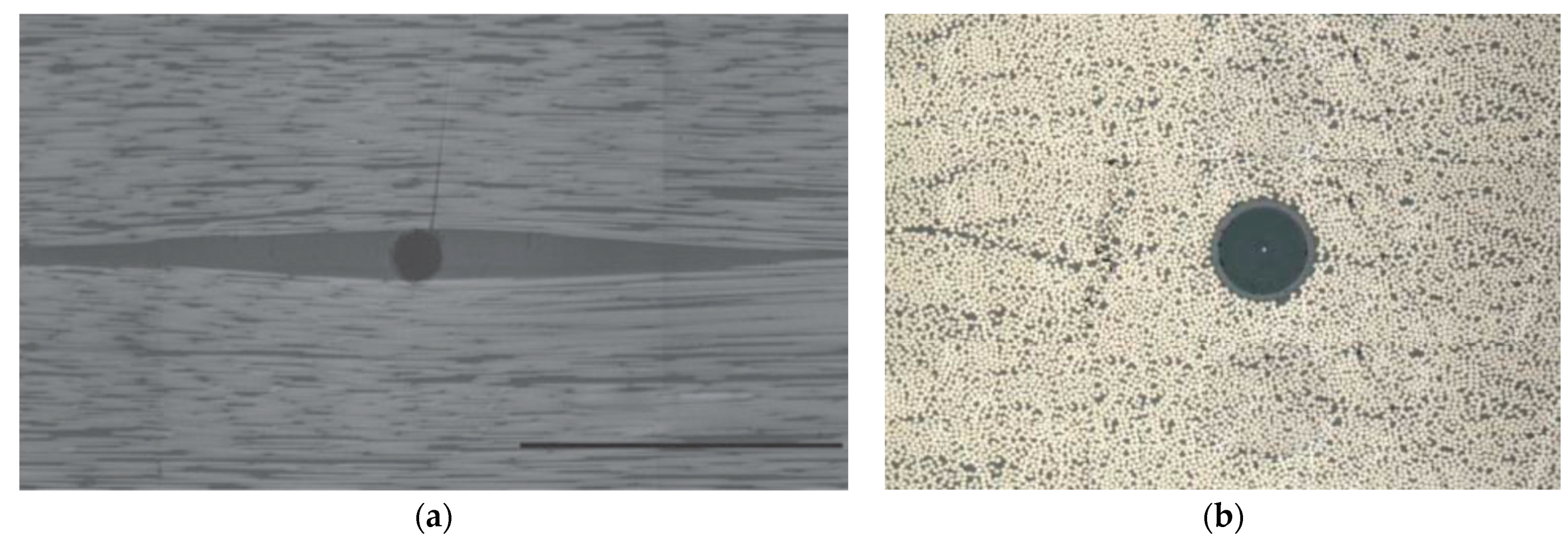
FBG or Rayleigh fibres can be surface-applied or integrated in the structure. On the surface, they do not modify the characteristics of the material. Once in the core of the composite, the optical fibre size, usually about 100–150 µm, is much greater than the composites reinforcing fibres, less than 20 μm for carbon or glass fibres. It results in the creation of a gap between the optical fibres and the reinforcement fibres, as shown in Figure 3, thus inducing resin rich regions.
Figure 3. OF embedded in a composite (
a) perpendicularly to the fibres (diameter 80 µm and scale bar 500 µm)
[27] and (
b) in the fibres axis (diameter 125 µm)
[28].
2.2. Monitoring Techniques Used in Failure Analysis
2.2.1. Visual Inspection
To date, the periodic structural health inspection of wind turbine blades is made by professional climbers while the wind turbine is shut down. The inspection is mainly limited to visual inspection and simple manual tapping tests with a hammer
[29][30]. It allows detecting surface damages in defined critical areas. For internal damages, the tapping method requires an expertise to distinguish between the damaged and undamaged structure.
2.2.2. Performance Analysis
A wind turbine structure, working in its optimal state, exhibits a certain level of performance (power, nominal voltage, angle of inclination of the blades, current, speed of the blades, etc.). When the structure degrades, performance is changed despite identical operating conditions
[31]. Consequently, the analysis of various operating parameters enables to identify the presence of damages on the structure when deviations are important compared to the optimum performances
[10][12].
2.2.3. Acoustic Emission (AE)
Acoustic Emission (AE) is known as the emission of elastic waves with low amplitude ranges and high frequency (from 100 kHz to 1 MHz)
[1][32]. The AE waves are generated within the material by the release of energy. Therefore, AE is a passive non-destructive evaluation technic (NDE) because the excitation source is the core material without any additional external source. Typical sources of AE are initiation and propagation of cracks, breakage of fibres, fracture of the matrix, friction between different surfaces, deformation, delamination, and impacts
[1][33]. The detection of the AE waves is made by a surface sensor. The different failures in the structure can be detected depending on different characteristics of the emitted signal, i.e., counts, rise time, peak amplitude, arrival time, duration, and signal energy content
[32]. This technique is commonly used in the industry for the control of composites
[30][34][35], and allows steady-state wind turbine blade control
[1]. This method is already protected with several patents
[36][37][38][39].
2.2.4. Ultrasonic Measurements
Unlike acoustic emission, which is a passive NDE, ultrasonic measurement (US) is an active monitoring technic. In addition to the received signal, an external excitation source is emitted. This signal propagates within the structure, is thus affected by the material which modified its characteristics (change of phase, defect, delamination, interfacial problems...)
[33][10][35][40]. The use of ultrasonic waves enables to obtain information on the material’s state. Three main techniques exist, named
pulse-echo,
thickness, and
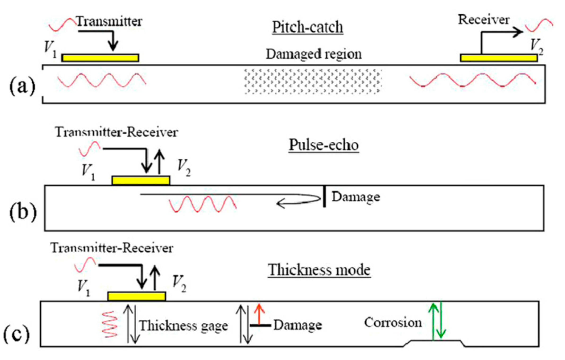
pitch-catch as illustrated in
Figure 4. In
echo-pulse mode, the wave is sent orthogonally to the material by a transducer which is attached to the surface. The reflection of the wave allows to obtain information on the various defects (type, depth). In
thickness mode, the wave is sent through the thickness of the structure, and the reflected wave enables to collect similar information as that in the
pulse-echo mode.
Figure 4. Damage detection with propagating and standing guided waves: (
a) pitch-catch, (
b) pulse-echo, and (
c) thickness mode
[41].
2.2.5. Vibrational Analysis
The analysis of a structure vibrations parameters, such as the frequency, and their variation, enables to measure the structure deformation and the appearance and propagation of cracks
[10][40]. Depending on the vibration frequencies, varying from 0.01 Hz to 100 kHz
[40], different sensors are used, from motion and speed sensors to accelerometers and emitted energy sensor. This technic has been identified as promising and patented in the field of wind blades
[42].
2.2.6. Radiography
Observation by X-ray in transmission provides an image of the state of the material
[31].
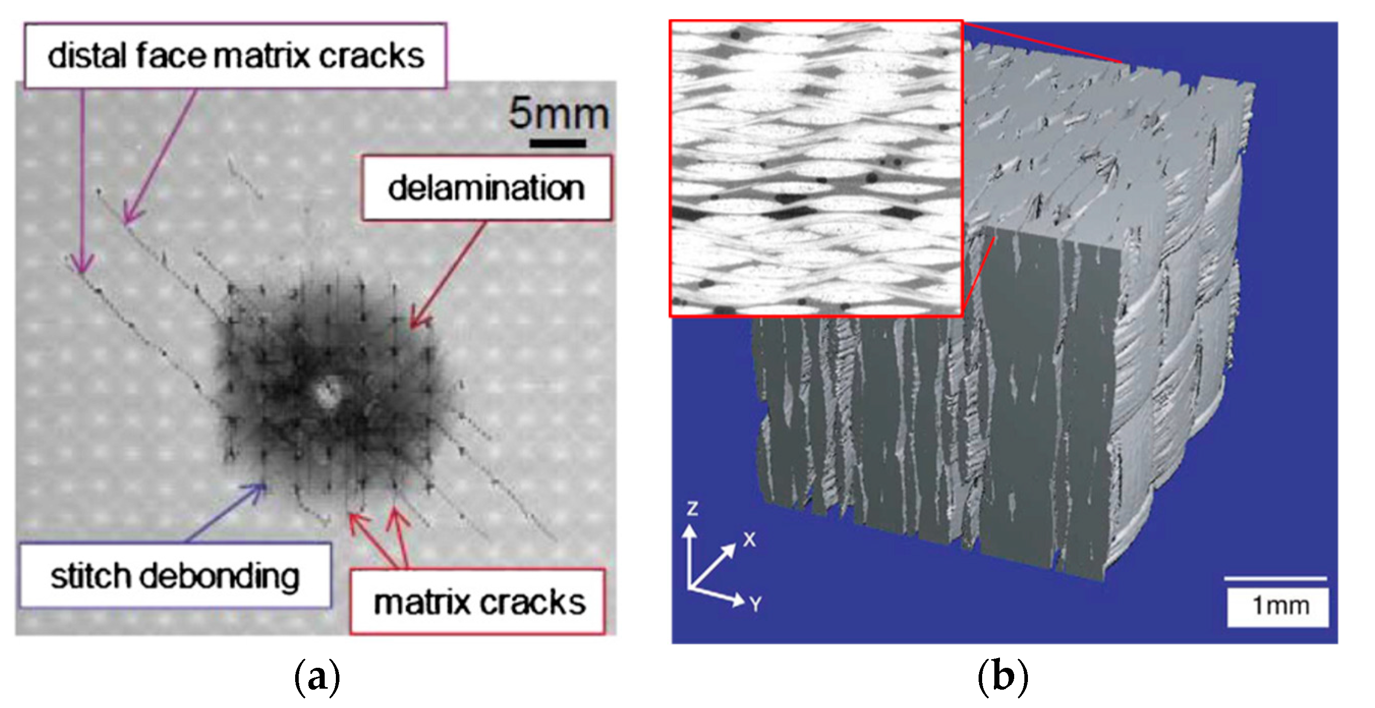
Figure 5a, produced by Tan et al.
[43], shows an X-ray images of a 6.1 mm thick CFRP laminate after a 6.7 J impact, where different resulting damages have been identified. As shown in
Figure 5b with a 3D reconstruction of a GFRP sample, this technique enables to identify the presence of defects such as breaks, delaminations, lacks of adhesive, vacuums, or shifts in the fibres orientation
[33][10][40][44]. The detection limit is about 10 μm, and this technique is sensitive to a variation of up to 1–2% of the material thickness. It is also possible to retrieve information on the variation of the materials’ density from the backscattering of X-rays. This technique enables to quickly obtain a state of the structure because the set of images is obtained simultaneously. On the other hand, it is a complicated technique to implement because it requires greater security measures due to the X-rays hazard. It is therefore used to control the quality of the structure after manufacturing.
This entry is adapted from the peer-reviewed paper 10.3390/jcs6020032
