Submitted Successfully!
To reward your contribution, here is a gift for you: A free trial for our video production service.
Thank you for your contribution! You can also upload a video entry or images related to this topic.
Version Summary Created by Modification Content Size Created at Operation
1 + 1987 word(s) 1987 2021-06-17 07:43:20 |
2 format correction Meta information modification 1987 2021-06-24 05:44:17 |

Video Upload Options

We provide professional Video Production Services to translate complex research into visually appealing presentations. Would you like to try it?

Confirm

Are you sure to Delete?
Cite
If you have any further questions, please contact Encyclopedia Editorial Office.
Wu, T. Mini-LED and Micro-LED. Encyclopedia. Available online: https://encyclopedia.pub/entry/11217 (accessed on 21 November 2024).
Wu T. Mini-LED and Micro-LED. Encyclopedia. Available at: https://encyclopedia.pub/entry/11217. Accessed November 21, 2024.
Wu, Tingzhu. "Mini-LED and Micro-LED" Encyclopedia, https://encyclopedia.pub/entry/11217 (accessed November 21, 2024).
Wu, T. (2021, June 24). Mini-LED and Micro-LED. In Encyclopedia. https://encyclopedia.pub/entry/11217
Wu, Tingzhu. "Mini-LED and Micro-LED." Encyclopedia. Web. 24 June, 2021.
Mini-LED and Micro-LED
Edit

The mini-LEDs with chip sizes ranging from 100 to 200 μm have already been commercialized for backlight sources in consumer electronics applications. The realized local diming can greatly improve the contrast ratio at relatively low energy consumptions. The micro-LEDs with chip size less than 100 μm, still remain in the laboratory.

mini-LED micro-LED full-color display quantum dot

1. Introduction

The traditional display technology features a cathode ray tube (CRT) based on the principle of a steered electron beam excitation of a fluorescent screen [1]. The structure of CRT is basically a vacuum tube with one or more built-in electron guns, which produce the electrons to be accelerated and steered. The steered electron beam excites one or more of the pixels on the screen designed to emit red, green, and blue (RGB), primary colors. By appropriate scanning, an image is produced on the phosphor pixelated screen. Since the invention of the first color CRT television (TV) in 1950, the CRT TV has dominated the display market for many decades because of its outstanding characteristics, such as excellent visual depth of field and high response rate. This dominance of CRT displays remained for a remarkably long time until the year of 2000, when two new display technologies, liquid-crystal display (LCD) and plasma display panel, were demonstrated [2][3][4]. Because of portability and power efficiency features, they are very popular with consumers. Later, owing to the continuous improvement in reducing the cost and performance improvements in the LCD technology, the plasma display shortly thereafter became uncompetitive. However, because LCD displays have major disadvantages, such as slow response time, poor conversion efficiency and low color saturation, the technology had been repeatedly criticized by consumers [5]. Consequently, the LCD manufacturers have taken steps to improve LCD displays, such as replacing the common liquid crystal materials with high response materials, using relatively larger conversion efficiency backlight modules, and utilizing high color saturation fluorescent materials. As a result, some high performance LCDs possess extremely short response times and thus are used in several virtual reality (VR) devices [6][7]. In recent years, new display technologies have become more mature, such as organic light-emitting diode (OLED) display and light-emitting diode (LED) displays [8]. The OLED display technology was developed in the 1990s. Compared with LCD displays, OLED displays have advantages, among which are self-luminous, wide viewing angle, high contrast, power saving, fast response, etc. [9][10]. However, due to limitations in material science and mass production capabilities, OLEDs are not as widely used in consumer electronics market as LCDs [11]. The LED-pixel based displays are mainly applied to large outdoor screens with the advantages of power saving, high color saturation and high brightness [12]. If LEDs are used as pixels of the display, the size of LEDs would need to be reduced according to the desired resolution. Because a growing number of manufacturers regard the LED display as the next- generation display technology, the onset of mini-LED and micro-LED has been triggered [13]. The comparison between mini-LED and micro-LED is shown in Table 1. The size of mini-LEDs is about 100~200 µm, which is between the size of conventional LEDs (>200 µm) and micro-LEDs (<100 µm).
Table 1. Comparison between mini-LED and micro-LED.
 

Mini-LED

Micro-LED

Size (μm)

100~200

<100

Purpose

Backlight for LCD

Self-emitting display

Features

High dynamic range, power saving, thin

High contrast, high efficiency, high resolution, high response time

Yield

>80%

Hard to estimate

Application

LCD backlight—From small to large LCD panel

Micro-projection display, display from small to large size

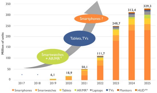
According to the Research and Markets, a market research institution, the global micro-LED display market is predicted to soar from USD 0.6 billion in 2019 to USD 20.5 billion in 2025, with a compound annual growth rate of about 80% [14]. The main reason for the market outbreak is the sharp increase in demand for brighter and more energy-efficient display panels, needed for surging devices such as smart watches, mobile phones, TVs, laptops, augmented reality (AR) and VR. According to Yole’s optimistic estimate, the market of micro-LED display will reach 330 million units by 2025 (Figure 1) [15]. Although the prospects of market are highly optimistic at present, micro-LED displays still face technological challenges, especially in the cases for which some key technologies and process equipment have not yet been made sufficiently developed. Therefore, the relatively mature mini-LED is expected to be the first commercialized variety while the micro-LED display technology is still in its nascent state.
Figure 1. Forecast about the development of micro-LED displays.

2. Mini-LED

High dynamic range (HDR) is one of the important features for next generation displays [16]. To achieve HDR with contrast ratio (CR) higher than 100000:1, high peak brightness and excellent dark state of the display system are simultaneously required [17]. Although the best requirement for HDR is pixel level dimming, which is described as micro-LED technology, there are still some technological bottlenecks that make micro-LED harder to realize quick commercialization. Therefore, a compromising way to realize multi-zone local dimming for LCD is direct-lit mini-LED backlight. Mini-LED technology has much smaller size of LED, which means it can divide more dimming blocks in a certain size LED backlight. Recently, LED manufacturers have turned to research and develop mini-LED. Most of existing processes and equipment for conventional LED can be used continuously for fabrication of mini-LED.
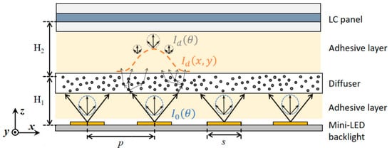
Tan et al. discussed the system modeling and performance evaluation of LCDs with mini-LED backlight [18]. First, a model of LCD system with a direct-lit mini-LED backlight is set up for simulation (Figure 2). The backlight unit consists of square-shaped mini-LED array. A diffuser plate is utilized to widen both spatial and angular distributions, and a liquid crystal (LC) panel is applied to control the output light. The parameters of the model, such as p, s, H1, and H2, are based on the device configuration reported in Reference [19]. To validate the model, four patterns are used to simulate the dynamic CR of the model, and the simulated results can agree with the measured data from Reference [19] reasonably well.
Figure 2. Schematic diagram of the model for the LCD with a mini-LED backlight [18]. Figure reproduced with permission from Optical Society of America.
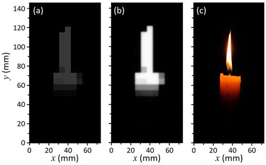
Next, the proved model is utilized to find out the relationship between the device structure to the final HDR display performance, especially the halo effect (Figure 3). Final HDR performance of displayed images are calculated via independently adjusting two key parameters of the device structure, the local dimming zone number and the LCD contrast ratio. According to simulation results, the dimming zone number mainly affects the halo area, while LCD contrast ratio influences the local image distortion, and more local dimming zones and higher LC contrast ratio can reduce the halo effect and improve the display performance.
Figure 3. Displayed image simulation: (a) Mini-LED backlight modulation; (b) luminance distribution of the light incident on LC layer; and (c) displayed image after LCD modulation [18]. Figure reproduced with permission from Optical Society of America.
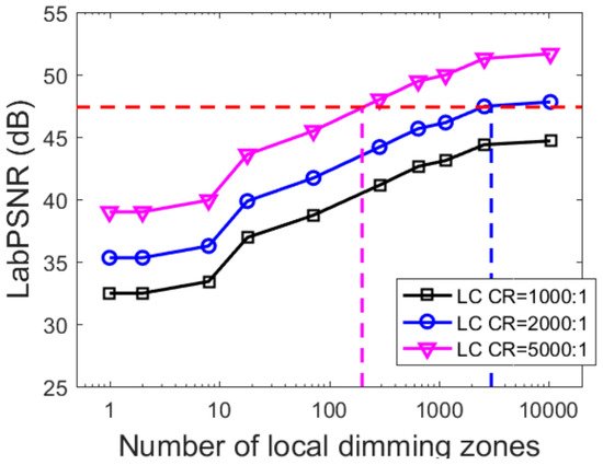
Then, a subjective experiment is designed and carried out to determine the human visual perception limit of halo effect. The LabPSNR, an evaluation metric used to quantify the difference between displayed image and target image, should be larger than 47.4 dB. Based on this limit, the requirement of local dimming zone number can be proposed: over 200 local dimming zones for high CR ≈ 5000:1 LCD panels and more than 3000 dimming zones for CR ≈ 2000:1 LCDs (Figure 4).
Figure 4. Simulated LabPSNR for different HDR display systems with various local dimming zone numbers and LC contrast ratios [18]. Figure reproduced with permission from Optical Society of America.
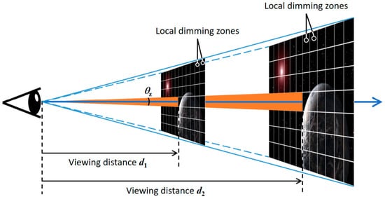
Although the above simulations and experiments are all based on the small-size smartphone displays with viewing distance at 25 cm, the analysis and conclusion can also be applied to display devices with different sizes and resolutions via converting the results from spatial domain to angular domain (Figure 5). In summary, Tan et al. demonstrated the required local dimming zone number to exhibit comparable HDR performance with OLED, and the HDR performance could not be achieved by conventional segmented LED backlight. The simulation model can provide useful guidelines to theoretically optimize the mini-LED backlit LCDs for achieving excellent HDR display.
Figure 5. Conceptual diagram of scaling up display size based on same angular size [18]. Figure reproduced with permission from Optical Society of America.
While mini-LED, an ideal backlight candidate for local dimming LCDs, is ready to be produced in volume at present, micro-LED still has to be processed inside laboratories and needs further preparation before entering the mass production. Many companies have joined the competition of mini-LED and tried to develop the mini-LED backlight technology to replace the traditional LCD backlight recently.
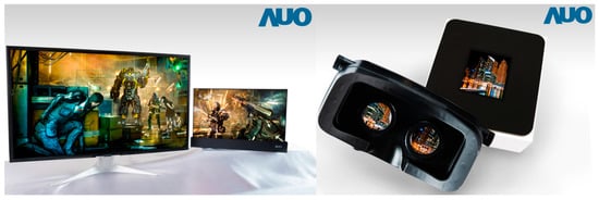
AU Optronics Corporation (AUO) demonstrated several high-end mini-LED backlit LCD displays, including a 27” 4K 144 Hz gaming monitor and a 1000 PPI 2” LTPS VR display (Figure 6) [20]. The gaming monitor used a straight down type mini-LED backlight to provide accurate local dimming with ultra-high brightness, creating a more realistic visual enjoyment for customer. However, the cost of mini-LEDs is still several times higher than traditional backlight technology at present. For head-mounted VR display, AUO shows a 2-inch panel equipped with an active matrix (AM) driver circuit which can achieve 1024 local dimming zones for vivid images.
Figure 6. The 27” gaming monitor and the 2” VR display of AUO.
JDI, a Japanese manufacturer, demonstrated an automotive central control panel based on a 16.7 inch curved screen with a straight down type mini-LED backlight at 2018 SID Display Week, shown in Figure 7a [21]. The contrast and color of the screen can be presented perfectly even in complex situations because of the local dimming with 104 dimming zones in the screen. BOE, one of the largest display makers in China, exhibited a 27-inch ultra-high-definition (UHD) panel, which used a mini-LED backlight with 1000 local dimming zones. Its brightness is up to 600 nits and its contrast is up to 1,000,000:1. In addition, BOE also showed a 5.9-inch mobile phone panel which was only 1.4 mm in thickness, shown in Figure 7b [21].
Figure 7. (a) The 16.7 inch curved automotive display with direct backlight solution of JDI. (b) Ultra-High Contrast UHD Display of BOE.

3. Micro-LED

As H. X. Jiang’s group in Texas Technique University reported the first fabrication of micro-LED chip with diameter of 12 µm in the year of 2000 [22][23][24], micro-LED has become a hot topic soon after the inception.
The application field of LEDs varies depending on the chip size. Due to the size difference, the traditional LED chip is mainly used in general lighting [25][26][27] and display backlight module [28]. The mini-LED is applied to backlight applications such as HDR and flexible displays [18], while the micro-LED is suitable for applications such as wearable watches, mobile phones, automotive head-up displays, AR/VR, micro projectors, and high-end televisions [29] (Table 2). Additionally, micro-LED can be combined with a flexible substrate to realize the flexible characteristics like OLED [30]. Therefore, micro-LED displays have the potential to match or exceed today’s OLED displays, with its high contrast, low power consumption, high brightness, and especially the high life-span [31].
Table 2. Requirements for mini-LED and micro-LED in typical applications.

Application

Auto Display

TV

Digital Display

Applsci 08 01557 i001

Applsci 08 01557 i002

Applsci 08 01557 i003

Panel Size (inch)

6~12

32~100

150~220

PPI

150~250

40~80

20~30

Chip volume (M)

4.1

24.9

24.9

Chip Size (μm)

50~100

50~80

80~100

Application

AR

Watch

Mobile

Applsci 08 01557 i004

Applsci 08 01557 i005

Applsci 08 01557 i006

Panel Size (inch)

0.5~1

1~1.5

4~6

PPI

450~2000

200~300

300~800

Chip volume (M)

49.8

0.4

6.2

Chip Size (μm)

1~5

10~30

30~50

At present, the micro-LED display technology still faces some challenges, like the transfer printing of micro-LED chips for mass production [32][33][34] and the full-color method for display applications [35][36][37]. With the rapid development of some transfer printing approaches summarized in Table 3, the first problem is expected to be effectively solved. Thus, we will focus on methods of fabricating the full-color display for micro-LEDs.
Table 3. Massively selective transfer printing methods.
 

Company

Principle

Description

Electrostatic array

LuxVue

Applsci 08 01557 i007

The transfer heads are divided by the dielectric layer to form a pair of silicon electrodes, which are positively and negatively charged, respectively, before picking up the target LED.

Magnetic array

ITRI

Applsci 08 01557 i008

Micro-LEDs are adsorbed and placed by the electromagnetic force generated by the coil.

Elastomer stamp

X-Celeprint

Applsci 08 01557 i009

The pick-up and transfer processes are aided by the Van der Waals forces between the viscoelastic elastomer stamp and the solid micro-LEDs.

Roll to plate

KIMM

Applsci 08 01557 i010

A roll-based transfer technology for transferring nanoscale objects from a donor substrate to a target substrate with high yields and productivity.

References

  1. Robert, L.; Barbin, A.S.P. Cathode-ray tube displays. In Wiley Encyclopedia of Electrical and Electronics Engineering; Wiley Online Library: Hoboken, NJ, USA, 1999.
  2. Weber, L.F. History of the plasma display panel. IEEE Trans. Plasma Sci. 2006, 34, 268–278.
  3. Chang, N.; Choi, I.; Shim, H. DLS: Dynamic backlight luminance scaling of liquid crystal display. IEEE Trans. Very Large Scale Integr. (VLSI) Syst. 2004, 12, 837–846.
  4. Boeuf, J.P. Plasma display panels: Physics, recent developments and key issues. J. Phys. D Appl. Phys. 2003, 36, R53–R79.
  5. Schadt, M. Milestone in the History of Field-Effect Liquid Crystal Displays and Materials. Jpn. J. Appl. Phys. 2009, 48.
  6. Peng, F.L.; Chen, H.W.; Gou, F.W.; Lee, Y.H.; Wand, M.; Li, M.C.; Lee, S.L.; Wu, S.T. Analytical equation for the motion picture response time of display devices. J. Appl. Phys. 2017, 121.
  7. Li, C.-H.; Lu, S.-H.; Lin, S.-Y.; Hsieh, T.-Y.; Wang, K.-S.; Kuo, W.-H. Ultra-fast moving-picture response-time LCD for virtual reality application. In SID Symposium Digest of Technical Papers; Wiley Online Library: Hoboken, NJ, USA, 2018; Volume 49, pp. 678–680.
  8. Tang, C.W.; Vanslyke, S.A. Organic electroluminescent diodes. Appl. Phys. Lett. 1987, 51, 913–915.
  9. Geffroy, B.; Le Roy, P.; Prat, C. Organic light-emitting diode (OLED) technology: Materials, devices and display technologies. Polym. Int. 2006, 55, 572–582.
  10. Chen, H.W.; Tan, G.J.; Wu, S.T. Ambient contrast ratio of LCDs and OLED displays. Opt. Express 2017, 25, 33643–33656.
  11. Chen, H.-W.; Lee, J.-H.; Lin, B.-Y.; Chen, S.; Wu, S.-T. Liquid crystal display and organic light-emitting diode display: Present status and future perspectives. Light Sci. Appl. 2018, 7, 17168.
  12. Lv, X.; Loo, K.H.; Lai, Y.M.; Tse, C.K. Energy-saving driver design for full-color large-area LED display panel systems. IEEE Trans. Ind. Electron. 2014, 61, 4665–4673.
  13. Templier, F. GaN-based emissive microdisplays: A very promising technology for compact, ultra-high brightness display systems. J. Soc. Inf. Display 2016, 24, 669–675.
  14. Micro-LED Market by Application, Display Panel Size, Vertical, and Geography-Global Forecast to 2025. Available online: (accessed on 30 July 2018).
  15. MicroLED Displays Could Disrupt LCD and OLED. Available online: (accessed on 30 July 2018).
  16. Seetzen, H.; Heidrich, W.; Stuerzlinger, W.; Ward, G.; Whitehead, L.; Trentacoste, M.; Ghosh, A.; Vorozcovs, A. High dynamic range display systems. In ACM Transactions on Graphics (TOG); ACM: New York, NY, USA, 2004; Volume 23, pp. 760–768.
  17. Daly, S.; Kunkel, T.; Sun, X.; Farrell, S.; Crum, P. Viewer preferences for shadow, diffuse, specular, and emissive luminance limits of high dynamic range displays. In SID Symposium Digest of Technical Papers; Wiley Online Library: Hoboken, NJ, USA, 2013; Volume 44, pp. 563–566.
  18. Tan, G.J.; Huang, Y.G.; Li, M.C.; Lee, S.L.; Wu, S.T. High dynamic range liquid crystal displays with a mini-LED backlight. Opt. Express 2018, 26, 16572–16584.
  19. Deng, Z.; Zheng, B.; Zheng, J.; Wu, L.; Yang, W.; Lin, Z.; Shen, P.; Li, J. High dynamic range incell LCD with excellent performance. In SID Symposium Digest of Technical Papers; Wiley Online Library: Hoboken, NJ, USA, 2018; Volume 49, pp. 996–998.
  20. AUO’s Full Series of Mini LED Backlit LCDs Make Stunning Appearance to Establish Foothold in High-End Application Market. Available online: (accessed on 30 July 2018).
  21. [Display Week 2018 Show Report]-Mini LED Backlight Business Opportunities Boost. Available online: (accessed on 30 July 2018).
  22. Jin, S.X.; Li, J.; Li, J.Z.; Lin, J.Y.; Jiang, H.X. GaN microdisk light emitting diodes. Appl. Phys. Lett. 2000, 76, 631–633.
  23. Jin, S.X.; Li, J.; Lin, J.Y.; Jiang, H.X. InGaN/GaN quantum well interconnected microdisk light emitting diodes. Appl. Phys. Lett. 2000, 77, 3236–3238.
  24. Jiang, H.X.; Jin, S.X.; Li, J.; Shakya, J.; Lin, J.Y. III-nitride blue microdisplays. Appl. Phys. Lett. 2001, 78, 1303–1305.
  25. Wu, T.; Lin, Y.; Zhu, H.; Guo, Z.; Zheng, L.; Lu, Y.; Shih, T.; Chen, Z. Multi-function indoor light sources based on light-emitting diodes-a solution for healthy lighting. Opt. Express 2016, 24, 24401–24412.
  26. Wu, T.; Lu, Y.; Guo, Z.; Zheng, L.; Zhu, H.; Xiao, Y.; Shih, T.; Lin, Y.; Chen, Z. Improvements of mesopic luminance for light-emitting-diode-based outdoor light sources via tuning scotopic/photopic ratios. Opt. Express 2017, 25, 4887–4897.
  27. Wu, T.; Lin, Y.; Zheng, L.; Guo, Z.; Xu, J.; Liang, S.; Liu, Z.; Lu, Y.; Shih, T.; Chen, Z. Analyses of multi-color plant-growth light sources in achieving maximum photosynthesis efficiencies with enhanced color qualities. Opt. Express 2018, 26, 4135–4147.
  28. Wang, L.; Wang, X.; Kohsei, T.; Yoshimura, K.-I.; Izumi, M.; Hirosaki, N.; Xie, R.-J. Highly efficient narrow-band green and red phosphors enabling wider color-gamut LED backlight for more brilliant displays. Opt. Express 2015, 23, 28707–28717.
  29. Jiang, H.X.; Lin, J.Y. Nitride micro-LEDs and beyond—A decade progress review. Opt. Express 2013, 21, A475–A484.
  30. Tian, P.; McKendry, J.J.D.; Gu, E.; Chen, Z.; Sun, Y.; Zhang, G.; Dawson, M.D.; Liu, R. Fabrication, characterization and applications of flexible vertical InGaN micro-light emitting diode arrays. Opt. Express 2016, 24, 699–707.
  31. Zhang, K.; Peng, D.; Lau, K.M.; Liu, Z. Fully-integrated active matrix programmable UV and blue micro-LED display system-on-panel (SoP). J. Soc. Inf. Display 2017, 25, 240–248.
  32. Zhang, L.; Ou, F.; Chong, W.C.; Chen, Y.J.; Li, Q.M. Wafer-scale monolithic hybrid integration of Si-based IC and III-V epi-layersA mass manufacturable approach for active matrix micro-LED micro-displays. J. Soc. Inf. Display 2018, 26, 137–145.
  33. Cok, R.S.; Meitl, M.; Rotzoll, R.; Melnik, G.; Fecioru, A.; Trindade, A.J.; Raymond, B.; Bonafede, S.; Gomez, D.; Moore, T.; et al. Inorganic light-emitting diode displays using micro-transfer printing. J. Soc. Inf. Display 2017, 25, 589–609.
  34. Corbett, B.; Loi, R.; Zhou, W.D.; Liu, D.; Ma, Z.Q. Transfer print techniques for heterogeneous integration of photonic components. Prog. Quantum Electron. 2017, 52, 1–17.
  35. Chanyawadee, S.; Lagoudakis, P.G.; Harley, R.T.; Charlton, M.D.B.; Talapin, D.V.; Huang, H.W.; Lin, C.H. Increased color-conversion efficiency in hybrid light-emitting diodes utilizing non-radiative energy transfer. Adv. Mater. 2010, 22, 602–606.
  36. Zhuang, Z.; Guo, X.; Liu, B.; Hu, F.; Li, Y.; Tao, T.; Dai, J.; Zhi, T.; Xie, Z.; Chen, P.; et al. High color rendering index hybrid III-nitride/nanocrystals white light-emitting diodes. Adv. Funct. Mater. 2016, 26, 36–43.
  37. Kang, C.-M.; Lee, J.-Y.; Park, M.-D.; Mun, S.-H.; Choi, S.-Y.; Kim, K.; Kim, S.; Shim, J.-P.; Lee, D.-S. Hybrid integration of RGB inorganic LEDs using adhesive bonding and selective area growth. In SID Symposium Digest of Technical Papers; Wiley Online Library: Hoboken, NJ, USA, 2018; Volume 49, pp. 604–606.
More
Information
Contributor MDPI registered users' name will be linked to their SciProfiles pages. To register with us, please refer to https://encyclopedia.pub/register :
View Times: 4.8K
Revisions: 2 times (View History)
Update Date: 24 Jun 2021
1000/1000
ScholarVision Creations