Submitted Successfully!
To reward your contribution, here is a gift for you: A free trial for our video production service.
Thank you for your contribution! You can also upload a video entry or images related to this topic.
Version Summary Created by Modification Content Size Created at Operation
1 + 5965 word(s) 5965 2021-05-19 07:54:12 |
2 format correct -21 word(s) 5944 2021-06-01 06:21:28 |

Video Upload Options

Do you have a full video?

Confirm

Are you sure to Delete?
Cite
If you have any further questions, please contact Encyclopedia Editorial Office.
Mohd Yunus, S. TBC-assisted Cooling Air System Simulation. Encyclopedia. Available online: https://encyclopedia.pub/entry/10337 (accessed on 28 March 2024).
Mohd Yunus S. TBC-assisted Cooling Air System Simulation. Encyclopedia. Available at: https://encyclopedia.pub/entry/10337. Accessed March 28, 2024.
Mohd Yunus, Salmi. "TBC-assisted Cooling Air System Simulation" Encyclopedia, https://encyclopedia.pub/entry/10337 (accessed March 28, 2024).
Mohd Yunus, S. (2021, June 01). TBC-assisted Cooling Air System Simulation. In Encyclopedia. https://encyclopedia.pub/entry/10337
Mohd Yunus, Salmi. "TBC-assisted Cooling Air System Simulation." Encyclopedia. Web. 01 June, 2021.
TBC-assisted Cooling Air System Simulation
Edit

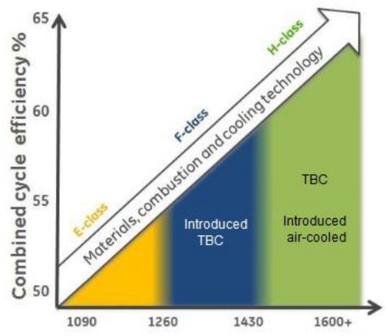
Thermal barrier coating (TBC) and cooling air systems are among the technologies that have been introduced and applied in pursuing the extensive development of advanced gas turbine. TBC is used to protect the gas turbine components from the higher operating temperature of advanced gas turbine, whereas cooling air systems are applied to assist TBC in lowering the temperature exposure of protected surfaces. Generally, a gas turbine operates in three main operational modes, which are base load, peak load, and part peak load. TBC performance under these three operational modes has become essential to be studied, as it will provide the gas turbine owners not only with the behaviors and damage mechanism of TBC but also a TBC life prediction in a particular operating condition.

thermal barrier coating cooling air system advanced gas turbine TBC simulation thermal oxidation test rig

1. Introduction

Gas turbines are used for many applications such as aircraft and ship propulsion, and power generation [1]. The use of the gas turbine is distinguished by the output power. There are two output powers produced by gas turbine, which are jet power for a jet engine and shaft power for power generation [2]. Jet power gas turbine is provided by the jet engine where no shaft power is used, which not similar to power generation in a gas turbine where shaft power has been used to generate power [3].
Specific to power generation application, rapid technology development has continually brought an incremental increase in gas turbine operating temperature, which aims to achieve higher efficiency and power output. The level of the hot gas temperature is now beyond the maximum material temperature of the gas turbine components [4]. For this reason, many technologies have been developed and applied, such as advanced superalloys; advanced thermal barrier coating (TBC); cooling systems, such as cooling air for hot gas path components; and advanced combustion systems [5][6][7][8][9]. TBC application in gas turbine is well-known and has been widely tested and discussed by researchers. However, this TBC technology alone does not completely perform in advanced gas turbine operating conditions. As highlighted by Prapamonthon et al. in their study, TBC does not effectively protect the underlying turbine blade at the trailing edge area [10]. Refer to Figure 1 to see the position of trailing edge in the turbine blade’s configuration. Ziaei-Asl and Tayefe Ramezanlou in their study found that the contour and configuration of turbine blade results in a difference in temperature reduction by TBC [11]. Temperature reduction by TBC is higher at the leading edge compared to trailing edge. Luabi and Hamza in their comparison study highlighted the importance of the use of a cooling air system together with TBC to minimize the hot spots of the turbine blade by the high turbine inlet temperature (TIT) [12].
Figure 1. A schematic of turbine blade showing both (a) pressure side and (b) suction side [13].
Hence, hybrid TBC-assisted cooling method is often chosen not only to protect the gas turbine hot gas path components, but also to increase the turbine inlet temperature and elongate the operating hours (OH) of the gas turbine operation. Hybrid TBC-assisted cooling method is where TBC provides an external film cooling to the perimeter surface of the protected components and is assisted by a cooling air system, which provides internal cooling within the body of the protected components.

2. Advanced Gas Turbines

Advanced gas turbine can be described as upgrading the standard gas turbine to improve its reliability in terms of prolonging design life, efficiency in terms of improved power output, and durability in terms of enhanced operational flexibility [14][15][16]. The upgraded works include the use of upgraded superalloys, improved cooling holes configuration in both external film cooling and internal cooling, the application of TBC, and the use of an upgraded combustion system. Advanced gas turbines not only benefit the owner in terms of better reliability and longer design life, but also the maintenance cost can be reduced by a reduced maintenance interval [14]. An upgraded combustion system allows for them to be operated using a variety of gas and liquid fuels, reduces emissions, and increases combustion firing temperature [17][18].
TBC has been applied on advanced gas turbine components to protect the components so that the operating temperatures can be increased. For example, the turbine MHPS M701F4 is the type F turbine with a TIT of 1350 °C. MHPS M701F4, having higher TIT than the other advanced turbines such as Alstom GT13E2 and Siemens SGT6-5000F, is shown in Figure 2 [19]. Figure 3 shows the development of advanced gas turbine with increasing TIT by Mitsubishi Heavy Industries (MHI)/MHPS. Mitsubishi Hitachi Power Systems, Ltd. (MHPS) is one of the largest original equipment manufacturers (OEMs) for power generation plants, which has shared the development of gas turbine technology by Takamura et al. [20]. MHPS is developing the next-generation class JAC gas turbine, featured with 1650 °C TIT. TIT is the theoretical temperature at the entry of the first stage stationary blade in the turbine section [21]. Improvement has been made by MHPS by applying an enhanced air-cooled system for cooling the combustor, ultra-thick TBC, and a compressor with a high-pressure ratio.
Figure 2. Summary on TIT applied in some advanced gas turbines [19].
Figure 3. Gas turbine development with increasing TIT by MHI/MHPS. Adapted with permission from ref. [22]. Copyright 2018 ASME.

2.1. TBC in Advanced Gas Turbines

Nickel base (Ni-based) material is the most used superalloy in gas turbine application due to its outstanding mechanical properties to withstand high temperature, aggressive corrosion, and different stress levels [23][24][25]. Different materials and grades of superalloy have been used to cater specific gas turbine operating conditions. However, superalloy materials have still suffered melt and spallation for a prolonged exposure and over a range of temperatures [23][24]. For example, Rani et al. conducted a failure investigation on uncoated turbine blade [26]. Figure 4 shows damages that were found from the physical condition of the blade. However, further investigation through a destructive test concluded that the blade failure is due to hot corrosion and overheating. Another example has been taken from the comprehensive study on uncoated, premature-failed turbine blade by Fathi et al., and it was found that the premature failure occurred at a temperature as low as 800 °C due to hot corrosion [27]. These two examples among a large number of gas turbine component failures have proven the limited capability of superalloys in a certain range of gas turbine operating temperature. With the increase of TIT in the growth of gas turbine technology, superalloys are not able to withstand a higher temperature than their melting point. TBC has been applied to protect the underlying components from the more aggressive operating conditions of an advanced gas turbine.
Figure 4. Damages found based on physical condition of the blade made of superalloy. Reprinted with permission from ref. [26]. Copyright 2018 Elsevier.
TBC provides thermal insulation, corrosion, and erosion resistance to the protected components that are exposed to the hot gases such as turbine blade, combustion chamber, and transition piece [28][29][30]. Most TBC systems consist of a bond coat layer for corrosion resistance and an insulating ceramic top coat layer [30]. Advanced gas turbine with increasing TIT is inseparable from the growth of TBC technology. With the increasing TIT, TBC is expected to be durable enough to the high temperature demand [31].
There are many factors that contribute to the performance and behaviors of TBC. Sankar et al. conducted an optimization study to determine the optimum ceramic material to be used as the top coat for gas turbine blade [32]. Mahalingam et al. performed a study on an advanced TBC system with the additional rare-earth elements lanthanum (La) and gadolinium (Gd) to enhance its durability [33]. In our previous study, we also discussed the thermal resistance of TBC with the additional rare-earth element of Gd in two types of TBC systems, which are a single layer ceramic top coat and multilayer ceramic top coat [34]. Deposition techniques have also been attributed to the performance and behaviors of the TBC. There are a number of TBC deposition techniques such as electron-beam physical vapor deposition (EB-PVD), atmospheric plasma spraying, (APS), suspension plasma spraying (SPS), and solution precursor plasma spraying (SPPS) [35][36]. The unique characteristics of TBC that are produced by each of these deposition techniques have contributed to the distinguished behaviors and performance. TBC by APS produced a laminar structure whereas TBC by either EB-PVD, SPS or SPPS produced a columnar structure. The good points of the laminar-structured APS TBC are the good mechanical properties and lower thermal conductivity [37][38]. In terms of the TBC performance, many studies have discussed the capability of the columnar-structured TBC in extending the thermal cycle fatigue (TCF) life compared to laminar-structured TBC [39]. SPS TBC is one of the promising deposition techniques that exhibits both a columnar structure and low thermal conductivity, which is similar to APS TBC [40].
Not only limited to the optimization study on TBC materials and the deposition techniques, the bond coat behavior has become a more important subject to be studied as most of the TBC failures initiate and propagate at the interface or within the bond coat [41]. The bond coat behaviors cover the growth of thermally grown oxide (TGO), adhesion strength, different thermal expansion coefficients, etc. A great number of researches have discussed the TBC failures due to TGO. TGO is the main root cause of TBC failure. Either under isothermal or thermal cyclic conditions, the TBC suffers failures at the top coat/TGO interface [36][37][38][42][43]. Thickening of TGO with the depletion of aluminum (Al) element in the bond coat results in the formation of mixed oxides, which form the weakest path within the TBC system. The thickening of TGO and its effects to the TBC performance in a particular gas turbine operating condition such as cracks propagation, stress concentration, and distribution have also been studied and discussed [33][44][45][46][47].
Adhesion strength between layers in the TBC system also plays an important role to ensure the durability and behavior of TBC. Studies on the adhesion strength between the layers and its underlying substrate have been widely conducted and discussed [48]. Another subject that is related to TBC performance is thermal expansion mismatch between layers. From the previous studies, it has been concluded that even bond coat has been used to minimize the mismatch effect, but in certain applications, the consequences such as TBC spallation due to this condition still occurred [49]. Up-to-date, the optimization study to determine optimum TBC system in a particular operating condition is still ongoing.

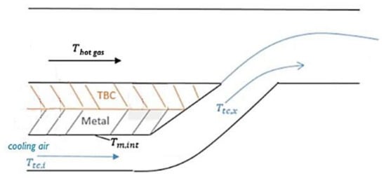
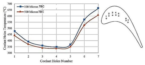
2.2. TBC-Assisted Cooling Air in Advanced Gas Turbine

In gas turbine technology, the use of cooling air has been introduced to reduce the surface temperature of hot gas path components such as turbine blade. However, the cooling air will reduce the efficiency of the turbine and thus reduce the overall power output of the gas turbine [48]. To overcome this problem, hybrid TBC-assisted cooling air has been introduced.
Almost all advanced gas turbines are installed with air cooled blades, where the relatively cool air from the compressor section is injected into the turbine section hybrid with TBC in reducing the temperature of hot gas path components [21][28]. For example, General Electric (GE), which is one of the largest gas turbine’s OEMs, has introduced air-cooled technology in the advanced gas turbine as an addition to the TBC application to increase the firing temperature, as shown in Figure 5. Uysal et al. have discussed the effectiveness of cooling air that is associated to the TBC on a blade in improving efficiency [50]. In the study, several models have been developed using software simulations, which have been used to quantify the effects attributed to the TBC alone, the cooling air system alone, and the combination of these two. The schematic modelling on the temperature exposures by both TBC and cooling air is shown in Figure 6.
Figure 5. Introduction of cooling air system in advanced gas turbine by GE. Adapted with permission from ref. [51]. Copyright 2018 ASME.
Figure 6. Schematic modelling on the effects of TBC and cooling air for a blade. Adapted with permission from ref. [50]. Copyright 2018 ASME.
Furthermore, Ziaei-Asl et al. have discussed the effects of TBC-assisted cooling air on the turbine blade performance [8]. The differences in temperature reduction by different TBC thicknesses and number of cooling holes have also been elaborated in the study, and the summary is shown in Figure 7. Fujimoto et al. have discussed the upgrading works that have been conducted to optimize the hybrid TBC-assisted cooling air by increasing the TBC thickness and modifying the shape of the cooling hole [16]. Taniguchi et al. in their work modified the turbine blade cooling holes to improve the cooling performance [31]. Software simulations have been conducted to study the cooling air performance for a variety of cooling holes’ configuration.
Figure 7. Optimization study on TBC thickness and number of holes for advanced gas turbine. Reprinted with permission from ref. [8]. Copyright 2019 Elsevier.
In actual gas turbine operation, the internal surface of cooling holes is not protected with any coating system. A study conducted by Sabri et al. found that the cooling holes with oval shape, which have relatively wider hole openings, have suffered severe pitting and oxidation [52]. Wider hole openings have allowed for the ingestion of debris and for contaminant particles to enter the cooling holes internal surface. Both experimental and numerical studies that have been conducted by Jiang et al. also has found the undesirable effect by the larger cooling holes, which exhibited higher local stress, thus resulting in rapid cracks propagation; this was similarly discussed by Wang et al. [53][54]. Many studies show TBC-assisted cooling air method is proven, but the optimization studies on the synchronization between these two, TBC and cooling air, are still on-going.

3. TBC Life

Gas turbines are operated as per demand. TBC life will change according to the gas turbine operational mode [55]. There are three general descriptions for gas turbine operational modes:
i.
Peak load: operation for 3 to 4 h with two startups. One typical cycle of gas turbine consists of a startup and a shutdown.
ii.
Part peak load: operation for 19 h, followed by stopping for 5 h with one startup.
iii.
Base load: operation for 24 h, generally 8000 equivalent operating hours (EOH) per year.
Peak load is defined as operation above base load and is achieved by increasing turbine operating temperatures. Peak load required short OH as little as 15 min with two or three start/stops per day [20]. Significant operation at peak load requires more frequent maintenance and replacement of hot gas path and combustion components [55]. Under part peak load, the load will be reduced from the peak load. The percentage of load in part peak load is adjusted from peak load to optimize the fuel consumption and production level [21]. Base load is defined as operation with long OH per start and the hot gas path components are not subjected to the cyclic thermal stresses corresponding to startup and shutdown. Under base load operation, the gas turbines are expected to run for extended periods without shutting down and normally operate at constant load [56].
The load is one of the contributing factors that influences the performance of the gas turbine [57]. The increment in the percentage (%) of applied load indicates the increment of the gas turbine firing temperature. Higher firing temperature and more startups during peak load will increase the thermal stress that is experienced by the hot gas path components. More startups result in temperature and stress fluctuations that will be experienced by the TBC and the protected components. Also, the load will affect the efficiency of the turbine, as shown in Figure 8. This explains why a higher load is always chosen in gas turbine operation.
Figure 8. The relationship between load and the turbine efficiency in gas turbine operation [57].

4. TBC Simulation Test Rig

For a certain period of high temperature exposures, TBC experienced degradations such as sintering, hot corrosion, erosion, wear, foreign object damage (FOD) etc. Under real gas turbine operation, TBC will experience the combination of any of these, which will not only affect the thermal insulation performance of TBC, but also the efficiency of the cooling system [6]. In worst situations, premature failure of TBC will occur prior to the actual design life.
The gas turbine operational mode is one of the contributing factors that determined the TBC degradations. Base load with steady state condition and peak load with temperature fluctuations experienced by the TBC are believed to attribute to different mechanisms of the degradation process. Cyclic operation and higher TIT have proven to reduce the life of TBC [19]. A huge number of studies to simulate the high temperature exposures of TBC have been conducted. Based on three gas turbine general operational modes as mentioned above, researchers have developed methodologies, and sometimes also the custom-made test rigs, in order to simulate the operating conditions of TBC. Among the recent studies, the available TBC simulation test rigs have been compiled and divided into several groups based on mode of test. The summary on the grouping is shown in Figure 9.
Figure 9. Grouping of available test rigs for TBC in gas turbine (GT) simulative temperature exposures.
The available test rigs used in various TBC studies can be divided into two main groups, based on the actual gas turbine operational modes. Terms used by researchers: isothermal oxidation and thermal cyclic test, are determined by the TBC conditions in certain gas turbine operating modes and conditions.

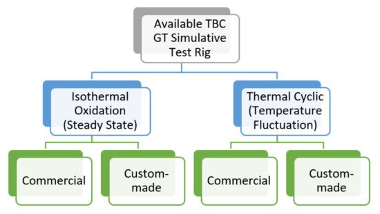
4.1. Thermal Cyclic Test Rig

Most TBC studies have been conducted under thermal cyclic test condition. Selected studies have been briefly described to present the available thermal cyclic test rig in simulating TBC. The selections are limited to thermal cyclic tests with test temperatures beyond 1000 °C to represent the advanced gas turbine operating temperatures.
Vaben et al. used custom-made burner rig to simulate TBC in thermal cyclic condition at 1500 °C, which was equipped with 1050 °C cooling air to determine the effects of transient cooling [58]. Transient cooling during the high temperature exposure of TBC will accelerate the failure. In the study, it was found that the cooling rate will bring a significant effect to the lifetime of TBC. At the cooling air rate of 100 K/s, the TBC lifetime will reduce by a factor of two to three as compared to the TBC with the cooling air rate of 10 K/s in thermal cyclic condition. This study shows the importance of cooling air effects on the performance of TBC.
Mahade et al. used a custom-made thermal shock burner rig to conduct the test at 1400 °C and the substrate surface remained at 1050 °C for the multi-layered TBC with the addition of a rare-earth element, gadolinium (Gd) [59]. Multi-layered TBC and the addition of rare-earth elements in typical TBC system has been widely discussed in recent studies, aiming to improve the properties of TBC and enhance the capability in higher exposed temperatures. Back to the thermal cyclic test conducted, the burner was removed from the TBC top coat surface after 5 min of heating, and the compressed air was applied for cooling mode. However, the temperature of the compressed air is not mentioned by the authors. Through this study, the performance of advanced TBC, which was featured with a multi-layer and additional rare-earth elements, was evaluated at a higher temperature of 1400 °C equipped with the cooling effect. Mahalingam et al. in their study also used a burner flame of 1400 °C for thermal cycle test to determine the thermal stability of TBC systems with different types of bond coats, where one was applied with air plasma spray (APS) and the other one was applied with high velocity oxygen fuel (HVOF) [60]. However, the evaluations in all these studies are limited to the TBC behaviors in cyclic condition, not in the prolonged, steady-state condition.
Wang et al. used a custom-made burner rig associated with calcium–magnesium–alumino-silicate (CMAS) feature to conduct the test at 1350 °C with 1150 °C cooling air [61]. This study has used the burner rig to determine the TBC performance under cyclic conditions. CMAS liquid was suspended on the TBC surface prior to the thermal cyclic test. Three TBC systems, distinguished by the weightage percentage (wt.%) of yttrium (Y) element, have been tested and ranked, and were compared by their ability in CMAS resistance. The burner rig used is shown to be capable to produce the ‘aged’ TBC under the designed experimental test parameters. Cooling air effect also has been taken into consideration, which it believed to simulate the working condition of TBC. However, the burner rig was operated under cyclic condition, not in the prolonged, steady-state condition.
Zhang et al. in their study conducted both isothermal oxidation and thermal cyclic tests on TBC system [62]. For isothermal oxidation test, TBC specimens were exposed to 1100 °C for a maximum of 100 h using muffle furnace. Thermal cyclic was conducted using a custom-made burner rig at 1225 °C. No cooling system was used in this study. Through this study, some presumptions were made. During the isothermal oxidation test using a commercial furnace, the whole perimeter surface of the TBC specimen was exposed to the test temperature of 1100 °C. This means, not only the TBC top coat surface, but the substrate surface were also exposed to the test temperature. The average melting temperature for Ni-based superalloys that are typically consumed in gas turbine and have been used as substrate material is approximately 1250 °C. Failure analysis that was conducted by Kolagar et al. found that Ni-based superalloy will experience overheating when exposed to temperatures beyond 1000 °C for a prolonged duration [63]. This finding can be related to the reason why 1100 °C has been selected by the authors for the isothermal oxidation test. The selected isothermal oxidation test temperature of 1100 °C is not as high as the temperature used in thermal cyclic test, 1225 °C. With no cooling air or other cooling system applied, the TBC specimens are expected to experience overheating and fail.
Ma et al. also conducted both isothermal oxidation tests for prolonged temperature exposure, and thermal shock test to simulate the thermal cyclic working condition of TBC [64]. The isothermal oxidation test was conducted using commercial air furnace at 1300 °C for a total exposure of 95 h. The thermal cyclic simulation was conducted also using the air furnace at 1200 °C. The authors conducted an isothermal oxidation test at temperatures beyond 1000 °C, which differs to the test conducted by Zhang et al. [62], as discussed above. There are possible reasons for the higher test temperature used. Ma et al. placed the TBC specimens in the crucibles made of alumina where the crucibles are capable of protecting the substrate surface from direct contact with furnace hot air [64]. The other thing is, the isothermal oxidation test was conducted for 20–25 h, and only then the specimens were taken out from the furnace and ambient air cooled prior to TGO measurement. Then the TBC specimens were placed back in the furnace to continue the isothermal exposure for another two to three cycles with similar methods until reaching the total of 95 h. Being protected by the crucibles and relatively short exposure time are the possible reasons for the exposures of the whole TBC specimens to temperatures beyond 1000 °C. The selected test temperatures beyond 1200 °C are believed to simulate TBC in the advanced gas turbine operating temperatures. The simulation for TBC in advanced gas turbine operating conditions seemed not to have been completed where no cooling feature was applied to attribute to the cooling effect.
Other than the custom-made burner rig, there was a facility developed, and this was used in the study by Yingsang et al. [65]. They used a high heat flux rig to simulate TBC in gas turbine working condition at the exposed temperature of 1150 °C with 950 °C cooling air. The laser power was used to provide the test temperature of 1150 °C and the coverage of heating was only at the middle surface of specimens. It was mentioned that the heating did not reach the edge of the specimens. In TBC evaluations, the condition of TBC edges should be considered as edge delamination is prone to occur on the coating system with the edge surface. There are many studies that have reported that edge delamination is one of the main damage mechanisms for TBC. For example, Jiang et al. reported that the interfacial cracks within TBC were initiated from the edge area and propagated through the interface during the cooling or shutdown period [66]. A study by Abedini, Dong and Davis used finite element method (FEM) on the TBC delamination by the edges [67]. The software simulation was conducted to optimize the interface conditions to minimize the occurrence of TBC edge delamination. Even the developed facility was equipped with the compressed air as the cooling device; the use of a laser should have improved heating on the whole TBC top coat surface, so that TBC could be simulated fully to establish the optimum TBC behavior including the resistance to edge delamination.
Liu et al. in their study conducted both isothermal oxidation and thermal cyclic tests to evaluate the performance of TBC for gas turbine blades application [68]. Thermal cyclic test was conducted using a custom-made furnace with automation specimen lifting, to simulate the TBC under cyclic conditions at 1100 °C. No cooling air or other cooling system was equipped in this custom-made furnace. While for isothermal oxidation test, commercial muffle furnace was used with the same test temperature of 1100 °C. As discussed in the previous section, hot gas path components including the blade are equipped with not only the TBC system, but also the cooling system such as air-cooled, for advanced gas turbine application. In this study, both isothermal oxidation test for prolonged exposure and thermal cyclic test for peak and/or part peak condition cannot represent the TBC simulation in advanced gas turbine, where no cooling system has been used in both custom-made and commercial test facilities.
TBC was tested under cyclic conditions either by using a custom-made test rig that was equipped with the cooling air system [58][59][60][61][65], that was not equipped with the cooling air system [68], or a commercial test rig that was not equipped with the cooling air system [62][64]. These showed that there are a number of studies have developed test rigs that are capable of simulating TBC-assisted cooling air system. However, the above-mentioned articles are limited to the TBC simulation under cyclic conditions.
For certain studies without a cooling system, a number of limitations have occurred, such as limited materials can be applied especially for those substrates where typically the melting temperatures of the materials are below 1250 °C. Also, the test temperature is limited to the materials used in the TBC system. These two factors may limit the full potential to explore the performance of TBC assisted with cooling air in simulative advanced gas turbine conditions. For example, Xiao et al. and Negami et al. have used commercial furnace and custom-made hydrogen burner rig, respectively, to conduct TBC thermal cyclic tests at similar test temperature of 1080 °C [69][70]. A number of studies were conducted using commercial furnaces such as by Doleker et al. at a test temperature of 1150 °C [71]; Goral et al., Shamsipoor et al., Fritscher et al. and Barhanko et al. all used a test temperature of 1100 °C [72][73][74][75]; and Adam et al. and Taleghani et al. used test temperatures of 1050 °C and 1000 °C, respectively [76][77]; and Yang et al. and Jing et al. both used commercial muffle furnace with a test temperature of 1050 °C [78][79]. However, without cooling air or other cooling system equipped, the tests are limited to certain temperatures that do not represent the actual exposure of advanced gas turbine specifically under cyclic conditions.
For isothermal oxidation test, most researchers have used commercial furnace or equipment to simulate TBC in steady-state operating condition. Similar to thermal cyclic test, the selected studies that will be briefly described later are having TBC temperature exposures beyond 1000 °C only. The selections are of relevance with the high temperature of advanced gas turbines.

4.2. Isothermal Oxidation Test Rig

Similar to TBC that has been tested under cyclic conditions, TBC under steady-state condition also shows that a small number of studies have been conducted using a custom-made test rig. For example, Fan et al. conducted the isothermal oxidation test using high voltage heating equipment to simulate the TBC at the maximum temperature of 1800 °C for 40 h [80]. The voltage was applied on the TBC top coat surface until it reached the intended temperature. Under this study, an extremely high temperature has been tested for advanced TBC application, but this does not represent the steady-state condition of TBC in advanced gas turbine working condition when no cooling system is equipped. The use of high voltage to provide a high temperature TBC top coat is a brilliant idea where the temperature can be achieved efficiently. However, there is still a need to include the cooling system during the TBC test rig simulation to get complete performance and behavior for advanced gas turbine application. The other important thing that needs to be considered thoroughly is the safety aspect during the test.
Nau et al. used a high pressure test rig to achieve the operating temperature of 1526.85 °C [81]. The purpose of their study is to determine the feasibility of the device in measuring the combustor wall in a high temperature and high pressure environment. A probe was used to represent TBC-coated combustor wall. Even the main idea of the study regards the measurement technique and device, but the concept that they have been introduced to exposes the probe, which is a TBC specimen, to a high temperature beyond 1500 °C. Figure 10 shows the test rig facility used in the study. Referring to the figure, TBC top coat surface can be exposed to high temperature but no cooling system is applied to completely simulate the TBC in advanced gas turbine application. Some modifications can be made to achieve this working condition.
Figure 10. Schematic of the test rig used by. Adapted with permission from ref. [81]. Copyright 2019 ASME.
Naraparaju et al. used a mini turbine to simulate TBC [82]. The mini turbine, as shown in Figure 11, has a single stage compressor section, a combustor chamber, a vane section, and a rotating bladed disk. Two TBC systems were applied on the blades. The test was conducted at 1250 °C for 1 h. From the configuration of the mini turbine, it can be ascertained that the developed mini turbine is suitable to be used for former types of gas turbine. However, if some modifications can be made with the installation of suitable cooling system at the combustor chamber and the blade sections, the use of this mini turbine can be extended not only to study the performance of TBC but any aspect in advanced gas turbine application.
Figure 11. Mini turbine unit used by Naraparaju et al. in their study. Adapted with permission from ref. [82]. Copyright 2018 Elsevier.
Other than as discussed above, almost all available test rigs to simulate TBC under steady-state condition are of commercial furnace. The highest test temperature applied in the isothermal oxidation test using the commercial furnace was reported by Bobzin et al.; 1300 °C and 1200 °C for a prolonged exposure of 50 h [83]. In the study, a multilayer TBC system, which consists of typical 7YSZ and the use of a rare-earth element of lanthanum zirconate, La2Zr2O7, has been evaluated. As discussed in the previous section, the addition of rare-earth elements in TBC are widely studied, which adds a benefits by protecting the underlying components to higher temperature in advanced gas turbine. The use of a rare-earth element in the multilayer TBC conveys the author’s effort to evaluate the advanced TBC system, which is preferably applied in the advanced gas turbine. However, the use of commercial furnace does not completely represent the advanced gas turbine simulative operating condition.
Another example to be discussed is Karaoglanli et al. who used commercial furnace to simulate TBC at 1000 °C, 1100 °C, and 1200 °C for maximum prolonged exposures of 100 h [84]. A comparative study has been conducted where TBC specimens were deposited using two deposition techniques, APS and HVOF, has been evaluated. A limited test temperature of 1200 °C when commercial furnace is used for prolonged exposure is expected. To study the performance of TBC, a number of parameters need to be evaluated. The parameters included the addition of a rare-earth element, the thickness of each TBC layer, the test condition, which will represent the actual operating condition of the particular TBC, and the deposition technique used to produce the TBC system. Different deposition techniques, deposition parameters, and surface preparations all will affect the performance of TBC. The authors have successfully evaluated the TBC system produced with different deposition techniques. We can get some overviews on the behaviors of these TBC systems and this might help to predict which technique is suitable to our application. In power generation gas turbine fleet, each OEM may use different TBC deposition techniques on their gas turbine components. However, without the assistance of any cooling system, this study is not suitable to be applied in simulating the advanced gas turbine.
Other examples have used commercial furnace in their studies such as Essa et al. and Chen et al. where they simulated TBC in the maximum exposed temperature of 1150 °C for a prolonged exposure of 1970 h and 312 h, respectively [85][86]; and Yang et al. conducted the TBC prolonged isothermal oxidation test at 1150 °C for a maximum of 200 h using commercial muffle furnace [87].
A number of studies have been reported to conduct the TBC isothermal oxidation at 1100 °C. For example, Jonnalagadda et al. conducted the test with a maximum exposure of 3000 h using commercial furnace [88]; Goral et al. and Izadinia et al. conducted the test for 1000 h also using the commercial furnace [72][89]; Paraschiv et al. conducted the test for maximum 600 h [90]; and Vorkotter et al. used commercial thermogravimetric analyzer (TGA) for a maximum test exposure of 70 h [91]. The temperature of 1100 °C is the lowest maximum material temperature of gas turbine components that are made of superalloys and coated with TBC [4]. For the higher material temperature beyond 1200 °C, not only TBC has been applied on the superalloy components, but it also assisted with the cooling system. All these facts have explained why most of the studies that conducted isothermal oxidation tests on TBC-coated specimens using a commercial furnace, which is not equipped with any cooling system, chose 1100 °C as the test temperature. Xiao et al. in their study chose a slightly lower test temperature of 1080 °C to conduct a TBC isothermal oxidation test for 1300 h using a commercial furnace [92].
Not only 1100 °C, but 1000 °C also has become a popular choice as the test temperature for TBC isothermal oxidation. Chang et al. in their study used real gas turbine material that was cut from the after-service blades from thermal power plants in Korea [93]. The scrapped specimens were then TBC coated and heat treated prior to a prolonged 8000 h exposure using a furnace. Three test temperatures have been selected, which are 850 °C, 950 °C, and 1000 °C. The behavior of TBC-coated specimens that were exposed to these temperatures under steady-state condition was evaluated. Many studies have also been reported to choose 1000 °C in isothermal oxidation test. For example, Taleghani et al. conducted the test using a commercial furnace for a maximum exposure period of 200 h [77]; Zulkifli et al. used a commercial furnace to isothermally expose the TBC specimens for 120 h [94]; Karaoglanli et al., Shi et al., Zakeri et al. and Doleker et al. also used a commercial furnace for 100-h isothermal oxidation test [95][96][97][98]; whereas Shi et al. and Doleker et al. used a commercial muffle furnace with a similar test duration [32][99].
The above-mentioned articles [80][81][82] do not consider the addition of cooling systems in their work. Studies that have been conducted using typical commercial furnace [32][72][77][83][84][85][86][87][88][89][90][91][92][93][94][95][96][97][98][99] have also proven to not be capable of simulating the cooling air effect on TBC in advanced gas turbine operating condition. The developed custom-made test rigs are also limited to short test duration under cyclic condition and no cooling air effect under prolonged steady-state operating conditions. TBC in advanced gas turbine operating condition should be equipped with the cooling air effect to get the optimum degraded TBC to be studied.

References

  1. Redko, A.; Redko, O.; DiPippo, R. Industrial waste heat resources. In Low-Temperature Energy Systems with Applications of Renewable Energy; Academic Press: Cambridge, MA, USA, 2020; pp. 329–362.
  2. Langston, L.S. Aspects of Gas Turbine Thermal Efficiency. Mech. Eng. 2020, 142, 54–55.
  3. Winterbone, D.E.; Turan, A. Gas Turbines. Adv. Thermodyn. Eng. 2015, 381–422.
  4. Anand, V.G.K.; Parammasivam, K.M. Thermal barrier coated surface modifications for gas turbine film cooling: A review. J. Therm. Anal. Calorim. 2020.
  5. Nagabandi, K.; Pujari, A.K.; Iyer, D.S. Thermo-mechanical assessment of gas turbine combustor tile using locally varying thermal barrier coating thickness. Appl. Therm. Eng. 2020, 179, 115657.
  6. Shi, L.; Long, Y.; Wang, Y.; Chen, X.; Zhao, Q. On-line detection of porosity change of high temperature blade coating for gas turbine. Infrared Phys. Technol. 2020, 110, 103415.
  7. Kwon, H.M.; Moon, S.W.; Kim, T.S.; Kang, D.W. Performance enhancement of the gas turbine combined cycle by simultaneous reheating, recuperation, and coolant inter-cooling. Energy 2020, 207.
  8. Ziaei-Asl, A.; Ramezanlou, M.T. Thermo-mechanical behavior of gas turbine blade equipped with cooling ducts and protective coating with different thicknesses. Int. J. Mech. Sci. 2019, 150, 656–664.
  9. Moon, S.W.; Kwon, H.M.; Kim, T.S.; Kang, D.W.; Sohn, J.L. A novel coolant cooling method for enhancing the performance of the gas turbine combined cycle. Energy 2018, 160, 625–634.
  10. Prapamonthon, P.; Yooyen, S.; Sleesongsom, S.; Dipasquale, D.; Xu, H.; Wang, J.; Ke, Z. Investigation of Cooling Performances of a Non-Film-Cooled Turbine Vane Coated with a Thermal Barrier Coating Using Conjugate Heat Transfer. Energies 2018, 11, 1000.
  11. Ziaei-Asl, A.; Ramezanlou, M.T. Effects of Thermal Barrier Coating (TBC) Thickness on Temperature Distribution of Gas Turbine Blade. In Proceedings of the 3rd Conference on Advances in Mechanical Engineering (ICAME), Istanbul, Turkey, 19–21 December 2017.
  12. Luabi, A.; Hamza, N. Cooling Process of Gas Turbine Blade: A Comparison Study. Al Qadasiyah J. Eng. Sci. 2020, 13, 215–222.
  13. Zhang, F.; Liu, Z.; Liu, Z.; Diao, W. Experimental Study of Sand Particle Deposition on a Film-Cooled Turbine Blade at Different Gas Temperatures and Angles of Attack. Energies 2020, 13, 811.
  14. Daulay, M.S.H.; Sinurat, M.S.; Sinisuka, N.I.; Dinata, I.S.; Pujiatmoko, H.; Leilan, F.; Revina, T. Gas Turbine Upgrades at Muara Karang Block I Power Plant to Improve Performance and Availability. In Proceedings of the 2018 International Conference on Electrical Engineering and Computer Science (ICEECS), Bali, Indonesia, 13 November 2018.
  15. Torkaman, A.; Vogel, G.; Fiebiger, S.; Dietrich, D.; Washburn, R. Gas Turbine Cycle Upgrade and Validation for Heavy Duty Industrial Machines. In Proceedings of the ASME Turbomachinery Technical Conference and Exposition Volume 3: Coal, Biomass and Alternative Fuels; Cycle Innovations; Electric Power; Industrial and Cogeneration Applications; Organic Rankine Cycle Power Systems, Charlotte, NC, USA, 26–30 June 2017.
  16. Fujimoto, K.; Fukunaga, Y.; Hada, S.; Ai, T.; Yuri, M.; Masada, J. Technology Application to MHPS Large Flame F Series Gas Turbine. In Proceedings of the ASME Turbomachinery Technical Conference and Exposition Volume 3: Coal, Biomass, and Alternative Fuels; Cycle Innovations; Electric Power; Industrial and Cogeneration; Organic Rankine Cycle Power Systems, Oslo, Norway, 11–15 June 2018.
  17. Goldmeer, J.; York, W.; Glaser, P. Fuel and Combustion System Capabilities of GE’s F and HA Class Gas Turbines. In Proceedings of the ASME Turbomachinery Technical Conference and Exposition Volume 4B: Combustion, Fuels and Emissions, Charlotte, NC, USA, 26–30 June 2017.
  18. York, W.D.; Simons, D.W.; Fu, Y. Operational Flexibility of GE’s F-Class Gas Turbines with the DLN2.6+ Combustion System. In Proceedings of the ASME Turbomachinery Technical Conference and Exposition Volume 4B: Combustion, Fuels, and Emissions, Oslo, Norway, 11–15 June 2018.
  19. Aminov, R.Z.; Moskalenko, A.B.; Kozhevnikov, A.I. Optimal gas turbine inlet temperature for cyclic operation. J. Phys. Conf. Ser. 2018, 1111.
  20. Takamura, K.; Iijima, T.; Wakazono, S.; Hada, S.; Yuri, M.; Kataoka, M. Development of 1650 °C Class Next Generation JAC Gas Turbine based on J Experience. Mitsubishi Heavy Ind. Tech. Rev. 2019, 56, 1–9.
  21. Kotowicz, J.; Brzęczek, M.; Job, M. The thermodynamic and economic characteristics of the modern combined cycle power plant with gas turbine steam cooling. Energy 2018, 164, 359–376.
  22. Suzuki, K.; Matsumura, Y.; Takata, K.; Hada, S.; Yuri, M.; Masada, J. Evolution of mhps large frame gas turbines: J to air-cooled JAC. In Proceedings of the ASME Turbo Expo 2018: Turbomachinery Technical Conference and Exposition, Oslo, Norway, 11–15 June 2018; Volume 3, pp. 1–8.
  23. Chellaganesh, D.; Khan, M.A.; Jappes, J.T.W. Hot corrosion behaviour of nickel—Iron based superalloy in gas turbine application. Int. J. Ambient Energy 2018, 41, 1–14.
  24. Rakoczy, L.; Grudzień, M.; Tuz, L.; Pańcikiewicz, K.; Zielińska-Lipiec, A. Microstructure and Properties of a Repair Weld in a Nickel Based Superalloy Gas Turbine Component. Adv. Mater. Sci. 2017, 17.
  25. Avila-Davila, E.O.; Lopez-Hirata, V.M.; Saucedo-Muñoz, M.L.; Palacios-Pineda, L.M.; Ramirez-Vargas, I.; Cueto-Rodriguez, M.M.; Trapaga-Martinez, L.G.; Alvarado-Orozco, J.M. Study of Mechanical Degradation and Microstructural Characterization in a Ni-Based Superalloy Component of a Gas Turbine. Mater. Sci. Forum 2018, 941, 1248–1253.
  26. Rani, S.; Agrawal, A.K.; Rastogi, V. Failure investigations of a first stage Ni based super alloy gas turbine blade. Mater. Today Proc. 2018, 5, 477–486.
  27. Fathi, S.; Zangeneh, S.H.; Pahlavani, M. A Comprehensive Analysis of Premature Failure in a Cobalt-Based Superalloy X-45 Gas Turbine Vane. J. Fail. Anal. Prev. 2019, 19, 1337–1347.
  28. Al-Jibory, M.W.; Rashid, F.L.; Talib, S.M. Review on Cooling Enhancement of Different Shape Gas Turbine Ribbed Blade with Thermal Barrier Coating. Int. J. Sci. Res. Eng. Dev. 2020, 3, 313–329.
  29. Chen, S.; Zhou, X.; Song, W.; Sun, J.; Zhang, H.; Jiang, J.; Deng, L.; Dong, S.; Cao, X. Mg2SiO4 as a novel thermal barrier coating material for gas turbine applications. J. Eur. Ceram. Soc. 2019, 39, 2397–2408.
  30. Sahith, M.S.; Giridhara, G.; Kumar, R.S. Development and analysis of thermal barrier coatings on gas turbine blades—A Review. Mater. Today Proc. 2018, 5, 2746–2751.
  31. Taniguchi, T.; Tamai, R.; Muto, Y.; Takami, S.; Tanaka, R.; Ryu, M. Performance Improvement Program for Kawasaki Gas Turbine. In Proceedings of the ASME Turbomachinery Technical Conference and Exposition Volume 3: Coal, Biomass and Alternative Fuels; Cycle Innovations; Electric Power; Industrial and Cogeneration Applications; Organic Rankine Cycle Power Systems, Charlotte, NC, USA, 26–30 June 2017.
  32. Sankar, V.; Ramkumar, P.B.; Sebastian, D.; Joseph, D.; Jose, J.; Kurian, A. Optimized Thermal Barrier Coating for Gas Turbine Blades. Mater. Today Proc. 2019, 11, 912–919.
  33. Mahalingam, S.; Yunus, S.M.; Manap, A.; Afandi, N.M.; Zainuddin, R.A.; Kadir, N.F. Crack Propagation and Effect of Mixed Oxides on TGO Growth in Thick La–Gd–YSZ Thermal Barrier Coating. Coatings 2019, 9, 719.
  34. Yunus, S.M.; Johari, A.D.; Husin, S. Comparison on thermal resistance performance of YSZ and rare-earth GZ multilayer thermal barrier coating at 1250 °C Gas turbine combustor liner. J. Adv. Res. Fluid Mech. Therm. Sci. 2018, 52, 123–128.
  35. Mehta, A.; Vasudev, H.; Singh, S. Recent developments in the designing of deposition of thermal barrier coatings—A review. Mater. Today Proc. 2020, 26, 1336–1342.
  36. Lashmi, P.G.; Ananthapadmanabhan, P.V.; Unnikrishnan, G.; Aruna, S.T. Present status and future prospects of plasma sprayed multilayered thermal barrier coating systems. J. Eur. Ceram. Soc. 2020, 40, 2731–2745.
  37. Martins, J.P.; Chen, Y.; Brewster, G.; McIntyre, R.; Xiao, P. Investigation of the bond coat interface topography effect on lifetime, microstructure and mechanical properties of air-plasma sprayed thermal barrier coatings. J. Eur. Ceram. Soc. 2020, 40, 5719–5730.
  38. Lakiza, S.M.; Grechanyuk, M.I.; Ruban, O.K.; Redko, V.P.; Glabay, M.S.; Myloserdov, O.B.; Dudnik, O.V.; Prokhorenko, S.V. Thermal Barrier Coatings: Current Status, Search, and Analysis. Powder Met. Met. Ceram. 2018, 57, 82–113.
  39. Ganvir, A.; Gupta, M.; Kumar, N.; Markocsan, N. Effect of suspension characteristics on the performance of thermal barrier coatings deposited by suspension plasma spray. Ceram. Int. 2020, 47, 272–283.
  40. Gupta, M.; Musalek, R.; Tesar, T. Microstructure and failure analysis of suspension plasma sprayed thermal barrier coatings. Surf. Coat. Technol. 2020, 382.
  41. Öchsner, A.; Altenbach, H. State of the Art Thermal Barrier Coating (TBC) Materials and TBC Failure Mechanisms. Adv. Struct. Mater. Prop. Charact. Mod. Mater. 2017, 33, 441–452.
  42. Manap, A.; Seo, D.; Ogawa, K. Characterization of Thermally Grown Oxide on Cold Sprayed CoNiCrAlY Bond Coat in Thermal Barrier Coating. Mater. Sci. Forum 2011, 696, 324–329.
  43. Manap, A.; Nakano, A.; Ogawa, K. The Protectiveness of Thermally Grown Oxides on Cold Sprayed CoNiCrAlY Bond Coat in Thermal Barrier Coating. J. Therm. Spray Tech. 2012, 21, 586–596.
  44. Pankov, V.; Patnaik, P.C.; Chen, K. The Role of Thermally Grown Oxide in the Failure Thermal Barrier Coatings for Gas Turbine Engine Applications. In Proceedings of the Montreal Global Power and Propulsion Forum, Montreal, QC, Canada, 7–9 May 2018.
  45. Wei, Z.-Y.; Cai, H.-N.; Meng, G.-H.; Tahir, A.; Zhang, W.-W. An innovative model coupling TGO growth and crack propagation for the failure assessment of lamellar structured thermal barrier coatings. Ceram. Int. 2019, 46, 1532–1544.
  46. Shi, J.; Zhang, T.; Wang, B.; Zhang, X.; Song, L.; Hu, R. Temperature-Dependent Isothermal Oxidation Behavior of a Ni-20Cr-18W Superalloy in Static Air. J. Mater. Eng. Perform. 2020, 29, 2658–2666.
  47. Jiang, J.; Jiang, L.; Cai, Z.; Wang, W.; Zhao, X.; Liu, Y.; Cao, Z. Numerical stress analysis of the TBC-film cooling system under operating conditions considering the effects of thermal gradient and TGO growth. Surf. Coat. Technol. 2018, 357.
  48. Manap, A.; Okabe, T.; Ogawa, K.; Mahalingam, S.; Abdullah, H. Experimental and smoothed particle hydrodynamics analysis of interfacial bonding between aluminum powder particles and aluminum substrate by cold spray technique. Int. J. Adv. Manuf. Technol. 2019, 4519–4527.
  49. Mohammadi, M.; Kobayashi, A.; Javadpour, S.; Jahromi, S.A.J. Evaluation of hot corrosion behaviors of Al2O3-YSZ composite TBC on gradient MCrAlY coatings in the presence of Na2SO4-NaVO3 salt. Vacuum 2019, 167, 547–553.
  50. Uysal, S.C.; Liese, E.; Nix, A.C.; Black, J. A thermodynamic model to quantify the impact of cooling improvements on gas turbine efficiency. J. Turbomach. 2018, 140, 1–14.
  51. Vandervort, C. Advancements in H class gas turbines and combined cycle power plants. In Proceedings of the ASME Turbo Expo, Oslo, Norway, 11–15 June 2018; Volume 3, pp. 1–10.
  52. Sabri, K.; Gaceb, M.; Si-Chaib, M.O. Analysis of a Directionally Solidified (DS) GTD-111 Turbine Blade Failure. J. Fail. Anal. Prev. 2020, 20, 1162–1174.
  53. Jiang, J.; Wu, D.; Wang, W.; Zhao, X.; Ma, X.; Wang, B.; Shi, H.-J. Fracture behavior of TBCs with cooling hole structure under cyclic thermal loadings. Ceram. Int. 2019, 46, 3644–3654.
  54. Wang, S.; Zhang, Z. Failure Mechanism of Turbine Guide Vane and Oxide Composition Analysis on the Surface of Failure Vane Cracks. Eng. Fail. Anal. 2020, 117.
  55. Janawitz, J.; Masso, J.; Childs, C. GE Power & Water Heavy-Duty Gas Turbine Operating and Maintenance Considerations GER-3620M (02/15); GE Power & Water: Atlanta, GA, USA, 2015.
  56. Saravanamuttoo, H.I.H. Gas Turbines for Electric Power Generation. In Thermal Power Plants Vol. 3, EOLSS; University of New Brunswick: Fredericton, NB, Canada; ISBN 978-1-905839-28-5.
  57. Uddin, M.; Romlie, M.F.; Abdullah, M.F. Performance Assessment and Economic Analysis of a Gas-Fueled Islanded Microgrid—A Malaysian Case Study. Infrastructures 2019, 4, 61.
  58. Vaben, R.; Bakan, E.; Mack, D.; Martin, T.; Sohn, Y.J.; Sebold, D.; Guillon, O. Unique performance of thermal barrier coatings made of yttria-stabilized zirconia at extreme temperatures (>1500 °C). J. Am. Ceram. Soc. 2020.
  59. Mahade, S.; Curry, N.; Björklund, S.; Markocsan, N.; Joshi, S. Durability of gadolinium zirconate/YSZ double-layered thermal barrier coatings under different thermal cyclic test conditions. Materials 2019, 12, 2238.
  60. Mahalingam, S.; Manap, A.; Yunus, S.M.; Afandi, N. Thermal Stability of Rare Earth-PYSZ Thermal Barrier Coating with High-Resolution Transmission Electron Microscopy. Coatings 2020, 10, 1206.
  61. Wang, T.; Shao, F.; Ni, J.; Zhao, H.; Zhuang, Y.; Sheng, J.; Zhong, X.; Yang, J.; Tao, S. Corrosion behavior of air plasma spraying zirconia-based thermal barrier coatings subject to Calcium–Magnesium–Aluminum-Silicate (CMAS) via burner rig test. Ceram. Int. 2020, 46, 18698–18706.
  62. Zhang, L.; Fan, W.; Wang, Y.; Liu, K.; Wang, Z.Z.; Bai, Y. Oxidation Resistance of Plasma-Sprayed Double-Layered LC/YSZ Coatings with Different Thickness Ratios at High Temperatures. Oxid. Met. 2020, 94, 397–408.
  63. Kolagar, A.M.; Tabrizi, N.; Cheraghzadeh, M.; Shahriari, M.S. Failure analysis of gas turbine first stage blade made of nickel-based superalloy. Case Stud. Eng. Fail. Anal. 2017, 8, 61–68.
  64. Ma, X.; Rivellini, K.; Ruggiero, P.; Wildridge, G. Toward Durable Thermal Barrier Coating with Composite Phases and Low Thermal Conductivity. J. Therm. Spray Tech. 2020, 29, 423–432.
  65. Yingsang, W.; Pei-feng, H.; Yao, W.; McCay, M.H.; Edward, C.D.; David, M.; Lei, H.; Chao, W.; Hongqi, Z. Laser Thermal Gradient Testing and Fracture Mechanics Study of a Thermal Barrier Coating. J. Therm. Spray Technol. 2019, 28, 1239–1251.
  66. Jiang, J.; Ma, X.; Wang, B. Stress analysis of the thermal barrier coating system near a cooling hole considering the free-edge effect. Ceram. Int. 2020, 46, 331–342.
  67. Abedini, S.; Dong, C.; Davies, I.J. Mechanisms and control of edge interfacial delamination in a multilayer system containing a functionally graded interlayer. Surf. Coat. Technol. 2020, 382.
  68. Liu, H.; Li, S.; Jiang, C.Y.; Yu, C.T.; Bao, Z.B.; Zhu, S.L.; Wang, F.H. Preparation and oxidation performance of a low-diffusion Pt-modified aluminide coating with Re-base diffusion barrier. Corros. Sci. 2020, 168.
  69. Xiao, B.; Huang, X.; Robertson, T.; Tang, Z.; Kearsey, R. Sintering resistance of suspension plasma sprayed 7YSZ TBC under isothermal and cyclic oxidation. J. Eur. Ceram. Soc. 2020, 40, 2030–2041.
  70. Negami, M.; Hibino, S.; Kawano, A.; Nomura, Y.; Tanaka, R.; Igashira, K. Development of highly durable thermal barrier coating by suppression of thermally grown oxide. J. Eng. Gas Turbines Power 2018, 140, 1–8.
  71. Doleker, K.M.; Ozgurluk, Y.; Karaoglanli, A.C. Isothermal oxidation and thermal cyclic behaviors of YSZ and double-layered YSZ/La2Zr2O7 thermal barrier coatings (TBCs). Surf. Coat. Technol. 2018, 351, 78–88.
  72. Góral, M.; Swadźba, R.; Kubaszek, T. TEM investigations of TGO formation during cyclic oxidation in two- and three-layered Thermal Barrier Coatings produced using LPPS, CVD and PS-PVD methods. Surf. Coat. Technol. 2020, 394, 1–10.
  73. Shamsipoor, A.; Farvizi, M.; Razavi, M.; Keyvani, A.; Mousavi, B.; Pan, W. High-temperature oxidation behavior in YSZ coated Cr2AlC and CoNiCrAlY substrates. Surf. Coat. Technol. 2020, 401, 126239.
  74. Fritscher, K. Life and FCT Failure of Yttria- and Ceria-Stabilized EBPVD TBC Systems on Ni-Base Substrates. Oxid. Met. 2019, 91, 131–157.
  75. Barhanko, D.A.; Åberg, N.R.; Andersson, O.H. Development of Blade Tip Repair for SGT-700 Turbine Blade Stage 1, with Oxidation Resistant Weld Alloy. In Proceedings of the ASME Turbo Expo 2018: Turbomachinery Technical Conference and Exposition, Volume 6: Ceramics; Controls, Diagnostics, and Instrumentation; Education; Manufacturing Materials and Metallurgy, Oslo, Norway, 11–15 June 2018.
  76. Adam, M.; Kontermann, C.; Oechsner, M. A study on failure of double-layer thermal barrier coatings subjected to uniaxial compression tests using acoustic emission analysis and digital image correlation. Procedia Struct. Integr. 2018, 13, 1226–1231.
  77. Taleghani, P.R.; Valefi, Z.; Ehsani, N. Characterization and oxidation behaviour of nanostructured La2(Zr0.7Ce0.3)2O7/YSZ coatings prepared by calcined precursor precipitate plasma spraying. Surf. Eng. 2020, 1–14.
  78. Yang, S.; Yuan, H.; Zeng, W.; Guo, H. Chemo-thermo-mechanical modeling of EB-PVD TBC failure subjected to isothermal and cyclic thermal exposures. Int. J. Fatigue 2020, 141, 105817.
  79. Jing, F.; Yang, J.; Yang, Z.; Zeng, W. Critical compressive strain and interfacial damage evolution of EB-PVD thermal barrier coating. Mater. Sci. Eng. A 2020, 776, 139038.
  80. Fan, Y.; Fan, J.; Li, W.; Han, Y.; Lv, Y.; Cheng, H. Microstructure and ultra-high temperature isothermal oxidation behaviour of YSZ-particle-modified WSi2 coating. Surf. Coat. Technol. 2020, 397, 125982.
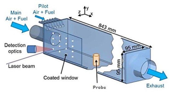
  81. Nau, P.; Yin, Z.; Lammel, O.; Meier, W. Wall Temperature Measurements in Gas Turbine Combustors with Thermographic Phosphors. J. Eng. Gas Turbines Power 2019, 141.
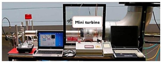
  82. Naraparaju, R.; Lau, H.; Lange, M.; Fischer, C.; Kramer, D.; Schulz, U.; Weber, K. Integrated testing approach using a customized micro turbine for a volcanic ash and CMAS related degradation study of thermal barrier coatings. Surf. Coat. Technol. 2018, 337, 198–208.
  83. Bobzin, K.; Brögelmann, T.; Kalscheuer, C.; Yildirim, B.; Welters, M. Correlation of thermal characteristics and microstructure of multilayer electron beam physical vapor deposition thermal barrier coatings. Thin Solid Film. 2020, 707, 138081.
  84. Karaoglanli, A.C.; Grund, T.; Turk, A.; Lampke, T. A comparative study of oxidation kinetics and thermal cyclic performance of thermal barrier coatings (TBCs). Surf. Coat. Technol. 2019, 371, 47–67.
  85. Essa, S.K.; Chen, K.; Liu, R.; Wu, X.; Yao, M.X. Failure Mechanisms of APS-YSZ-CoNiCrAlY Thermal Barrier Coating under Isothermal Oxidation and Solid Particle Erosion. J. Therm. Spray Technol. 2020.
  86. Chen, W.; Shan, X.; Li, J.; Guo, Y.; Guo, F.; Zhao, X.; Ni, N.; Xiao, P. Effects of iron and platinum on the isothermal oxidation of β-NiAl overlay coatings fabricated by spark plasma sintering. Surf. Coat. Technol. 2020, 382.
  87. Yang, H.Z.; Zou, J.P.; Shi, Q.; Wang, D.; Dai, M.J.; Lin, S.S.; Chen, X.; Wang, W.; Xia, X.P. Comprehensive study on the microstructure evolution and oxidation resistance performance of NiCoCrAlYTa coating during isothermal oxidation at High temperature. Corros. Sci. 2020, 175, 108889.
  88. Jonnalagadda, K.P.; Eriksson, R.; Li, X.H.; Peng, R.L. Fatigue life prediction of thermal barrier coatings using a simplified crack growth model. J. Eur. Ceram. Soc. 2019, 39, 1869–1876.
  89. Izadinia, M.; Soltani, R.; Sohi, M.H. Effect of segmented cracks on TGO growth and life of thick thermal barrier coating under isothermal oxidation conditions. Ceram. Int. 2020, 46, 7475–7481.
  90. Paraschiv, A.; Banu, A.; Doicin, C.; Ionica, I. Isothermal oxidation behavior of plasma sprayed conventional and nanostructured ysz thermal barrier coatings. UPB Sci. Bull. Ser. B Chem. Mater. Sci. 2020, 82, 163–174.
  91. Vorkötter, C.; Hagen, S.P.; Pintsuk, G.; Mack, D.E.; Virtanen, S.; Guillon, O.; Vaßen, R. Oxide Dispersion Strengthened Bond Coats with Higher Alumina Content: Oxidation Resistance and Influence on Thermal Barrier Coating Lifetime. Oxid. Met. 2019, 92, 167–194.
  92. Xiao, B.; Robertson, T.; Huang, X.; Kearsey, R. Fracture performance and crack growth prediction of SPS TBCs in isothermal experiments by crack numbering density. Ceram. Int. 2020, 46, 2682–2692.
  93. Chang, S.; Oh, K.-Y. Contribution of High Mechanical Fatigue to Gas Turbine Blade Lifetime during Steady-State Operation. Coatings 2019, 9, 229.
  94. Zulkifli, I.S.M.; Yajid, M.A.M.; Idris, M.H.; Uday, M.B.; Daroonparvar, M.; Emadzadeh, A.; Arshad, A. Microstructural evaluation and thermal oxidation behaviors of YSZ/NiCoCrAlYTa coatings deposited by different thermal techniques. Ceram. Int. 2020, 46, 22438–22451.
  95. Karaoglanli, A.C.; Ozgurluk, Y.; Doleker, K.M. Comparison of microstructure and oxidation behavior of CoNiCrAlY coatings produced by APS, SSAPS, D-gun, HVOF and CGDS techniques. Vacuum 2020, 180, 109609.
  96. Shi, J.; Zhang, T.; Sun, B.; Wang, B.; Zhang, X.; Song, L. Isothermal oxidation and TGO growth behavior of NiCoCrAlY-YSZ thermal barrier coatings on a Ni-based superalloy. J. Alloy. Compd. 2020, 844, 156093.
  97. Zakeri, A.; Bahmani, E.; Aghdam, A.S.R.; Saeedi, B.; Bai, M. A study on the effect of nano-CeO2 dispersion on the characteristics of thermally-grown oxide (TGO) formed on NiCoCrAlY powders and coatings during isothermal oxidation. J. Alloy. Compd. 2020, 835, 155319.
  98. Doleker, K.M.; Ozgurluk, Y.; Ahlatci, H.; Karaoglanli, A.C. Isothermal Oxidation Behavior of Gadolinium Zirconate (Gd2Zr2O7) Thermal Barrier Coatings (TBCs) produced by Electron Beam Physical Vapor Deposition (EB-PVD) technique. Open Chem. 2018, 16, 986–991.
  99. Doleker, K.M.; Karaoglanli, A.C.; Ozgurluk, Y.; Kobayashi, A. Performance of single YSZ, Gd2Zr2O7 and double-layered YSZ/Gd2Zr2O7 thermal barrier coatings in isothermal oxidation test conditions. Vacuum 2020, 177, 109401.
More
Information
Contributor MDPI registered users' name will be linked to their SciProfiles pages. To register with us, please refer to https://encyclopedia.pub/register :
View Times: 1.4K
Revisions: 2 times (View History)
Update Date: 23 Jun 2021
1000/1000