 +1 credit
| Version | Summary | Created by | Modification | Content Size | Created at | Operation |
|---|---|---|---|---|---|---|
| 1 | Qasim Zeeshan Ahmed | + 3021 word(s) | 3021 | 2021-04-06 09:37:06 | | | |
| 2 | Conner Chen | Meta information modification | 3021 | 2021-04-07 07:35:45 | | | | |
| 3 | Conner Chen | Meta information modification | 3021 | 2021-04-07 07:39:33 | | |
Video Upload Options
Technology facilitates humans, improves productivity and leads to a better quality of life. Technological developments and automation in vehicular networks will lead to better road safety and lower congestion in present urban areas where the traditional transport system is becoming increasingly disorganised and inefficient. Therefore, the development of the intelligent transport systems (ITS) concept has been proposed, with the aim and focus on improving traffic safety and providing different services to its users. There has been considerable research in ITS resulting in significant contributions .
1. System Architecture for Autonomous Vehicles
An ordinary vehicle can be converted into an autonomous one by adding some additional components including sensors that allow the vehicle to make its own decisions by sensing the environment and controlling the mobility of the vehicle [1][2][3][4]. Figure 1 illustrates the overall communication process/protocol in AVs and also lists the sensors, actuators, hardware and the software control required. The protocol architecture, explained below, is composed of four main stages and enables a Level 5 fully autonomous vehicle where all the users are passengers.
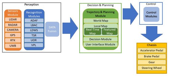
Figure 1. System Architecture for AVs.
-
Perception: This stage involves sensing of the AVs surrounding through various sensors and also detecting its own position with respect to the surroundings. In this stage, some of the sensors used by the AV are RADAR, LIDAR, camera, real-time kinetic (RTK), etc. The information from these sensors is then passed to the recognition modules which process this information. Generally, the AV consists of adaptive detection and recognition framework (ADAF), a control system, LDWS, TSR, unknown obstacles recognition (UOR), vehicle positioning and localisation (VPL) module, etc. This processed information is fused and passed to the decision and planning stage.
-
Decision and Planning: Utilising the data gathered in the perception process, this stage decides, plans and controls the motion and behaviour of the AV. This stage is analogous to the brain and makes decision such as path planning, action prediction, obstacle avoidance, etc. The decision is made based on the current as well as past information available including real-time map information, traffic details and patterns, information by the user, etc. There may be a data log module that records errors and information for future reference.
-
Control: The control module receives information from the decision and planning module and performs functions/actions related to physical control of the AV such as steering, braking, accelerating etc.
-
Chassis: The final stage includes the interface with the mechanical components mounted on the chassis such as the accelerator pedal motor, brake pedal motor, steering wheel motor and gear motor. All these components are signalled to and controlled by the control module.
After discussing the overall communication and sensor architecture of an AV, we discuss the design, functionality and utilisation of some main sensors.
1.1. Ultrasonic Sensors
These sensors use ultrasonic waves and operate in the range of 20–40 kHz [2]. These waves are generated by a magneto-resistive membrane used to measure the distance to the object. The distance is measured by calculating the time-of-flight (ToF) of the emitted wave to the echoed signal. Ultrasonic sensors have very limited range which is generally less than 3 m [5]. The sensor output is updated after every 20 ms [5], making it not compliant with the strict QoS constraints of an ITS. These sensors are directional and provide a very narrow beam detection range [2]. Therefore, multiple sensors are needed to to get a full-field view. However, multiple sensors will influence each other and can cause extreme ranging errors [6]. The general solution is to provide a unique signature or identification code which will be required to discard the echoes of other ultrasonic sensors operating in near-by range [7]. In AVs, these sensors are utilised to measure short distances at low speeds. For example, they are used for SPA and LDWS [8]. Moreover, these sensors work satisfactorily with any material (independent of color), in bad weather conditions and even in dusty environments.
1.2. RADAR: Radio Detection and Ranging
RADARs, in AVs, are used to scan the surroundings to detect the presence and location of cars and objects. RADARs operate in the millimetre-wave (mm-Wave) spectrum and are typically used in military and civil applications such as airports or meteorological systems [9]. In modern vehicles, different frequency bands such as 24, 60, 77 and 79 GHz are employed and they can measure a range from 5 to 200 m [10]. The distance between the AV and the object is calculated by measuring the ToF between the emitted signal and the received echo. In AVs, the RADARs use an array of micro-antennas that generate a set of lobes to improve the range resolution as well as the detection of multiple targets [11]. As mm-Wave RADAR has higher penetrability and a wider bandwidth, and it can accurately measure the short-range targets in any direction utilising the variation in Doppler shift [9][10][11][12]. Due to longer wavelength, mm-Wave radars have an anti-blocking and anti-pollution capability that allows them to cope in rain, snow, fog and low-light. Furthermore, mm-Wave radars have the ability to measure the relative velocity using the Doppler shift [13]. This ability of mm-Wave radars make them suitable for extensive AV application such as obstacle detection [14], pedestrian recognition [15] and vehicle recognition [16]. Some applications of RADARs in AVs are forward cross traffic alert (FCTA), lane change assistance (LCA), blind spot detection (BSD), rear cross traffic alert (RCTA), etc. The mm-Wave also has some disadvantages such as reduced field-of-view (FoV), less precision and results in getting more false alarm as a result of emitted signals which gets bounced from the surroundings [12].
1.3. LiDAR: Light Detection and Ranging
LiDAR utilises the 905 and 1550 nm spectra [17]. The 905 nm spectrum may cause retinal damage to the human eye, and, therefore, the modern LiDAR is operated in the 1550 nm spectrum to minimise the retinal damage [18]. The maximum working distance of LiDAR is up to 200 m [13]. LiDAR can be categorised into 2D, 3D and solid-state LiDAR [19]. A 2D LiDAR uses the single laser beam diffused over the mirror that rotates at high speed. A 3D LiDAR can obtain the 3D image of the surrounding by locating multiple lasers on the pod [20]. At present, the 3D LiDAR can produce reliable results with an accuracy of few centimetres by integrating 4–128 lasers with a horizontal movement of 360 degrees and the vertical movement of 20–45 degrees [21]. The solid-state LiDAR uses the micro-electromechanical system (MEMS) circuit with micro-mirrors to synchronise the laser beam to scan the horizontal FoV several times. The laser light is diffused with the help of a micro-mirror to create the vertical projection of the object. The received signal is captured by a photo-detector and the process repeats until the complete image of the object is created. LiDAR is used for positioning, obstacle detection and environmental reconstruction [13]. 3D LiDAR sensors are playing an increasingly significant role in the AV system [22]. As a result, the LiDARs can be used for ACC, 2D or 3D maps and object identification and avoidance. A roadside LiDAR system has shown to reduce the vehicle-to-pedestrian (V2P) crashes both at intersections and non-intersection areas [23]. In [23], a 16-line real-time computationally efficient LiDAR system is employed. Deep auto-encoder artificial neural network (DA-ANN) is proposed, which achieves an accuracy of 95% within a range of 30 m. In [24], a 64-line 3D LiDAR utilising a support vector machine (SVM)-based algorithm is shown to improve the detection of the pedestrian. Although LiDAR is superior to a mm-Wave radar in measurement accuracy and 3D perception, its performance suffers under severe weather conditions such as fog, snow and rain [25]. In addition, its operating range detection capability depends on the reflectiveness of the object [26].
1.4. Cameras
The camera in AVs can be classified as either visible-light based or infrared-based depending upon the wavelength of the device. The camera uses image sensors built with two technologies that are charge-coupled device (CCD) and a complementary metal-oxide-semiconductor (CMOS) [18]. The maximum range of the camera is around 250 m depending on the quality of the lens [13]. The visible cameras use the same wavelength as the human eye i.e., 400–780 nm, and is divided into three bands: Red, Green and Blue (RGB). To obtain the stereoscopic vision, two VIS cameras are combined with known focal length to generate the new channel with the depth (D) information. Such a feature allows the camera (RGBD) to obtain a 3D image of the scene around the vehicle [27].
The infrared (IR) camera uses passive sensors with a wavelength between 780 nm and 1 mm. The IR sensors in AVs provide vision control in peak illumination. This camera assists AVs in BSD, side view control, accident recording and object identification [28]. Nevertheless, the performance of the camera changes in bad weather conditions such as snow, fog and moment-of-light variation [13].
The main advantages of a camera are that it can gather and record the texture, color distribution and contour of the surroundings accurately [13]. However, the angle of observation is limited due to narrow view of the camera lens [29]. Therefore, multiple cameras have been adopted in AVs to monitor the surrounding environment [30][31]. A three-stage RGBD architecture using deep learning and convolutional neural networks was proposed by Ferraz et al. for vehicle and pedestrian detection [32]. However, this requires the AV to process huge amount of data [13]. Currently, AVs do not possess such computational resources; therefore, computational offloading may be an appropriate solution [33].
Table 4 summarises the challenges of the discussed sensor technologies. It can be observed in Table 4 that the detection capability and reliability of the various sensors is limited in different environments. This limitation can be overcome and the accuracy of target detection along with the reliability can be improved through multi-sensor fusion. Radar–camera (RC) [15][34], Camera–LiDAR (CL) [20][35], Radar–LiDAR (RL) [36] and Radar–Camera–LiDAR (RCL) [37][38] have been proposed where different sensors are combined together to improve the perception of the environment. Furthermore, in [2], three different sensor plans are developed based on range, cost and balance function. In this study, several different sensors are combined. In Plan A, four cameras, a mm-Wave RADAR, 32- and 4-layer LiDAR and a GPS+IMU are employed. In Plan B, four cameras, three mm-Wave RADAR, a four-layer LiDAR and a GPS+IMU are utilised. Finally, in Plan C, two regular cameras, three mm-Wave RADARs, a surrounding camera and a twelve-unit ultrasonic sensor are utilised.
Table 4. Comparison of sensor and their challenges.
| Sensor | Challenges |
|---|---|
| Ultrasonic Sensors |
|
| RADAR |
|
| LiDAR |
|
| Cameras |
1.5. GNSS and GPS, IMU: Global Navigation Satellite System and Global Positioning System, Inertial Measurement Unit
This technology can determine the exact position of the AV and helps it navigate [39]. GNSS utilises a set of satellites orbiting around the earth’s surface to localise [40]. The system contains the information of AV’s position, speed and the exact time [40]. It operates by calculating the ToF between the satellite emitted signal and the receiver [41]. The AV position is usually extracted from the Global Positioning System (GPS) coordinates. The extracted coordinates by GPS are not always accurate and they usually introduce an error in the position with a mean value of 3 m and a standard deviation of 1 m [42]. The performance is further degraded in urban environments and an error in position can increase up to 20 m [43] and in some extreme cases the GPS position error is around 100 m [44]. In addition to this, the RTK system can also be used in AVs to precisely calculate the position of the vehicle [45]. Furthermore, dead reckoning (DR) and the inertial position can also be used in AVs to determine the position and the direction of the vehicle [46]. A technique known as odometry can be used to measure the position of the vehicle by fixing the rotary sensors to the wheels of the vehicle [39]. To make the AV capable of detecting slippage or lateral movements, the inertial measurement unit (IMU) is used and it detects this using accelerometers, gyroscopes and the magnetometer sensor’s data. The IMU combined with all units can rectify the errors and increases the sampling speed of the measuring system. Although the IMU cannot provide the position error unless it is not accompanied by the GNSS system, AVs can get information from different sources such as RADAR, LiDAR, IMU, GNSS, UWB and camera to minimise the possibilities of error and perform reliable position measurement [18]. GPS can be combined with IMU techniques such as DR and the inertial position to confirm and improve the position estimate of the AV [47].
1.6. Sensor Fusion
Real-time and accurate knowledge of vehicle position, state and other vehicle parameters such as weight, stability, velocity, etc. are important for vehicle handling and safety and, thus, need to be acquired by the AVs using various sensors [48]. The process of sensor fusion is used to obtain coherent information by combining the data obtained from different sensors [13]. The process allows the synthesis action of raw data obtained from complimentary sources [49][50]. Therefore, sensor fusion allows the AV to precisely understand its surrounding by combining all the beneficial information obtained from different sensors [51]. The fusion process in AVs is carried out by using different types of algorithms such as Kalman filters and Bayesian filters. The Kalman filter is considered very important for a vehicle to drive independently because it is utilised in different applications such as RADAR tracking, satellite navigation system and visual odometry [52].
2. Vehicular Ad-Hoc Networks (VANETs)
VANETs are an emerging sub-class of mobile ad-hoc networks capable of spontaneous creation of a network of mobile devices/vehicles [53]. VANETs can be used for vehicle-to-vehicle (V2V) and Vehicle-to-Infrastructure (V2I) communication [54][55]. The main purpose of such technology is to generate security on the roads; for example, during hazardous conditions such as accidents and traffic jam the vehicles can communicate with each other and the network to share vital information [56][57]. The main components of VANET technology are:
-
On-board unit (OBU): It is a GPS-based tracking device embedded in every vehicle to communicate with each other and with roadside unit (RSU) [55][57]. To retrieve the vital information, the OBU is equipped with many electronic components such as resource command processor (RCP), sensor devices and user interfaces. Its main goal is to communicate between different RSUs and OBUs via a wireless link [54].
-
Roadside Unit (RSU): RSU is a computing unit fixed at specific location on roads, parking areas and intersections [58]. Its main goal is to provide connectivity between autonomous vehicle and the infrastructure and also assists in vehicle localisation [54][58]. It can also be used to connect vehicle with other RSUs using different network topologies [54]. They have also been powered using ambient energy sources such as solar power [59].
-
Trusted Authority (TA): It is an authority which manages the entire process for VANETs, so that only valid RSUs and vehicle OBUs can register and communicate [60]. It provides security by verifying the OBU ID and authenticates the vehicle. It also detects malicious messages or suspicious behaviour [54].
VANETs have some unique properties which are very different from other ad-hoc technologies.
-
The OBUs can move with predictable and regular path. It can help to detect the actual trajectory of the vehicle at any point of time [62]. The RSUs in VANETs can localise the vehicle and also log the path of the vehicle and also predict its trajectory to avoid any hazard.
-
The vehicle sensors and other nodes do not face any energy restrictions because they can extract energy from the vehicle engine.
-
The use of multicast broadcasting in VANETs allows the different vehicles to communicate with each other simultaneously [63].
Vehicular communication, utilising VANETs, includes V2V communication, V2I communication and V2X communication, as illustrated in Figure 2. The details are given below.
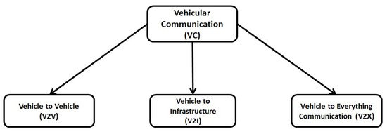
Figure 2. Vehicular communication (VC) system.
2.1. Vehicle-To-Vehicle (V2V) Communication
It is also called inter-vehicle communication (IVC) that allows the vehicles to communicate with each other and share the necessary information about traffic congestion, accidents and speed limits [64]. V2V communication can generate the network by connecting different nodes (Vehicles) using a mesh (partial or full) topology [65]. Depending upon the number of hops used for inter-vehicle communication, they are classified as single-hop (SIVC) or Multi-hop (MIVC) systems [66]. The SIVC can be used for short-range applications such as lane merging, ACC, etc., whereas MIVC can be used for long-range communication such as traffic monitoring. The V2V communication provides several advantages such as BSD, FCWS, automatic emergency braking (AEB) and LDWS [64].
2.2. Vehicle-To-Infrastructure (V2I) Communication
It is also known as roadside-to-vehicle communication (RVC) and allows the vehicles to interact with the RSUs. It helps to detect traffic lights, cameras, lane markers and parking meters [67]. The communication of vehicles with the infrastructure is ad-hoc, wireless and bidirectional [68]. The data collected from the infrastructure are used for traffic supervision and management. They are used to set different speed variables allowing the vehicles to maximise fuel efficiency as well as control the traffic flow [64]. Depending on the infrastructure, the RVC system can be divided into the Sparse RVC (SRVC) and the Ubiquitous RVC (URVC) [69]. The SRVC system provides communication services at hotspots only, for example to detect available parking spaces or gas stations, whereas the URVC system provides coverage throughout the road, even at high speeds. Therefore, the URVC system requires a large investment to ensure network coverage [69].
2.3. Vehicle-To-Everything (V2X) Communication
The V2X communication allows the vehicle to communicate with other entities such as pedestrians (V2P), roadside (V2R), devices (V2D) and the Grid (V2G) [70]. This communication is used to prevent road accidents with vulnerable pedestrians, cyclists and motorcyclists [71]. The V2X communication allows the Pedestrian Collision Warning (PCW) mechanism to alert the roadside passenger before any serious accident takes place. The PCW can access the Bluetooth or Near Field Communication (NFC) of the smartphone and may use beacon stuffing to deliver critical messages to the pedestrian [64].
References
- Zanchin, B.C.; Adamshuk, R.; Santos, M.M.; Collazos, K.S. On the instrumentation and classification of autonomous cars. In Proceedings of the IEEE International Conference on Systems, Man, and Cybernetics (SMC), Banff, AB, Canada, 5–8 October 2017; pp. 2631–2636.
- Zong, W.; Zhang, C.; Wang, Z.; Zhu, J.; Chen, Q. Architecture Design and Implementation of an Autonomous Vehicle. IEEE Access 2018, 6, 21956–21970.
- Jo, K.; Kim, J.; Kim, D.; Jang, C.; Sunwoo, M. Development of Autonomous Car—Part I: Distributed System Architecture and Development Process. IEEE Trans. Ind. Electron. 2014, 61, 7131–7140.
- Jo, K.; Kim, J.; Kim, D.; Jang, C.; Sunwoo, M. Development of Autonomous Car—Part II: A Case Study on the Implementation of an Autonomous Driving System Based on Distributed Architecture. IEEE Trans. Ind. Electron. 2015, 62, 5119–5132.
- Carullo, A.; Parvis, M. An ultrasonic sensor for distance measurement in automotive applications. IEEE Sens. J. 2001, 1, 143–147.
- Kim, H.; Lee, J.-H.; Kim, S.-W.; Ko, J.-I.; Cho, D. Ultrasonic vehicle detector for side-fire implementation and extensive results including harsh conditions. IEEE Trans. Intell. Transp. Syst. 2001, 2, 127–134.
- Agarwal, V.; Murali, N.V.; Chandramouli, C. A Cost-Effective Ultrasonic Sensor-Based Driver-Assistance System for Congested Traffic Conditions. IEEE Trans. Intell. Transp. Syst. 2009, 10, 486–498.
- Paidi, V.; Fleyeh, H.; Håkansson, J.; Nyberg, R.G. Smart parking sensors, technologies and applications for open parking lots: A review. IET Intell. Transp. Syst. 2018, 12, 735–741.
- Alluhaibi, O.; Ahmed, Q.Z.; Kampert, E.; Higgins, M.D.; Wang, J. Revisiting the Energy-Efficient Hybrid D-A Precoding and Combining Design for mm-Wave Systems. IEEE Trans. Green Commun. Netw. 2020, 4, 340–354.
- Farooq, A.; Ahmed, Q.Z.; Alade, T. Indoor Two Way Ranging using mm-Wave for Future Wireless Networks. In Proceedings of the Emerging Tech (EMiT) Conference 2019, Huddersfield, UK, 9–11 April 2019; University of Huddersfield: Huddersfield, UK, 2019.
- Li, Z.; Xiang, L.; Ge, X.; Mao, G.; Chao, H.-C. Latency and Reliability of mmWave Multi-Hop V2V Communications Under Relay Selections. IEEE Trans. Veh. Technol. 2020, 69, 9807–9821.
- Alluhaibi, O.; Ahmed, Q.Z.; Pan, C.; Zhu, H. Hybrid Digital-to-Analog Beamforming Approaches to Maximise the Capacity of mm-Wave Systems. In Proceedings of the IEEE 85th Vehicular Technology Conference (VTC Spring), Sydney, NSW, Australia, 4–7 June 2017; pp. 1–5.
- Wang, Z.; Wu, Y.; Niu, Q. Multi-Sensor Fusion in Automated Driving: A Survey. IEEE Access 2020, 8, 2847–2868.
- Alencar, F.A.; Rosero, L.A.; Filho, C.M.; Osorio, F.S.; Wolf, D.F. Fast metric tracking by detection system: Radar blob and camera fusion. In Proceedings of the 2015 12th Latin American Robotics Symposium and 2015 3rd Brazilian Symposium on Robotics (LARS-SBR), Uberlandia, Brazil, 29–31 October 2015; Volume 174, pp. 120–125.
- Etinger, A.; Balal, N.; Litvak, B.; Einat, M.; Kapilevich, B.; Pinhasi, Y. Non-imaging MM-wave FMCW sensor for pedestrian detection. IEEE Sens. J. 2014, 14, 1232–1237.
- Lee, S.; Yoon, Y.-J.; Lee, J.-E.; Kim, S.-C. Human-vehicle classification using feature-based SVM in 77-GHz automotive FMCW radar. IET Radar Sonar Navig. 2017, 11, 1589–1596.
- Wojtanowski, J.; Zygmunt, M.; Kaszczuk, M.; Mierczyk, Z.; Muzal, M. Comparison of 905 nm and 1550 nm semiconductor laser rangefinders’ performance deterioration due to adverse environmental conditions. Opto Electron. Rev. 2014, 22, 183–190.
- Rosique, F.; Navarro, P.; Fernández, C.; Padilla, A. A Systematic Review of Perception System and Simulators for Autonomous Vehicles Research. Sensors 2019, 29, 648.
- Li, Y.; Ibanez-Guzman, J. Lidar for Autonomous Driving: The Principles, Challenges, and Trends for Automotive Lidar and Perception Systems. IEEE Signal Process. Mag. 2020, 37, 50–61.
- Asvadi, A.; Garrote, L.; Premebida, C.; Peixoto, P.; Nunes, U.J. Multimodal vehicle detection: Fusing 3D-LIDAR and color camera data. Pattern Recognit. Lett. 2018, 115, 20–29.
- De Silva, V.; Roche, J.; Kondoz, A. Robust fusion of LiDAR and wide-angle camera data for autonomous mobile robots. Sensors 2018, 18, 2730.
- Zhao, S.; Yao, H.; Zhang, Y.; Wang, Y.; Liu, S. View-based 3D object retrieval via multi-modal graph learning. Signal Process. 2015, 112, 110–118.
- Zhao, J.; Xu, H.; Wu, J.; Zheng, Y.; Liu, H. Trajectory tracking and prediction of pedestrian’s crossing intention using roadside LiDAR. IET Intell. Transp. Syst. 2019, 13, 789–795.
- Wang, H.; Wang, B.; Liu, B.; Meng, X.; Yang, G. Pedestrian recognition and tracking using 3D LiDAR for autonomous vehicle. Robot. Auton. Syst. 2017, 88, 71–78.
- Rasshofer, R.; Spies, H.; Spies, M. Influences of weather phenomena on automotive laser radar systems. Adv. Radio Sci. 2011, 9, 49.
- Wallace, A.M.; Halimi, A.; Buller, G.S. Full Waveform LiDAR for Adverse Weather Conditions. IEEE Trans. Veh. Technol. 2020, 69, 7064–7077.
- Zhang, Z. A flexible new technique for camera calibration. IEEE Trans. Pattern Anal. Mach. Intell. 2000, 22, 1330–1334.
- Kannala, J.; Brandt, S.S. A generic camera model and calibration method for conventional, wide-angle, and fish-eye lenses. IEEE Trans. Pattern Anal. Mach. Intell. 2006, 28, 1335–1340.
- Swief, A.; El-Habrouk, M. A survey of automotive driving assistance systems technologies. In Proceedings of the 2018 International Conference on Artificial Intelligence and Data Processing (IDAP), Malatya, Turkey, 28–30 September 2018; pp. 1–12.
- Baftiu, I.; Pajaziti, A.; Cheok, K.C. Multi-mode surround view for ADAS vehicles. In Proceedings of the 2016 IEEE International Symposium on Robotics and Intelligent Sensors (IRIS), Tokyo, Japan, 17–20 December 2016; pp. 190–193.
- Delavarian, M.; Reza Marouzi, O.; Hassanpour, H.; Parizi, R.M.; Khan, M.S. Multi-camera multiple vehicle tracking in urban intersections based on multilayer graphs. IET Intell. Transp. Syst. 2020, 14, 1673–1690.
- Ferraz, P.A.P.; de Oliveira, B.A.G.; Ferreira, F.M.F.; Martins, C.A.P.d.S. Three-stage RGBD architecture for vehicle and pedestrian detection using convolutional neural networks and stereo vision. IET Intell. Transp. Syst. 2020, 14, 1319–1327.
- De Souza, A.B.; Rego, P.A.L.; Carneiro, T.; Rodrigues, J.D.C.; Filho, P.P.R.; Souza, J.N.D.; Chamola, V.; Albuquerque, V.H.C.D.; Sikdar, B. Computation Offloading for Vehicular Environments: A Survey. IEEE Access 2020, 8, 198214–198243.
- Reina, G.; Milella, A.; Rouveure, R. Traversability analysis for offroad vehicles using stereo and radar data. In Proceedings of the 2015 IEEE International Conference on Industrial Technology (ICIT), Seville, Spain, 17–19 March 2015; pp. 540–546.
- Shimizu, T.; Kobayashi, K. Development of a person-searching algorithm using an omnidirectional camera and LiDAR for the Tsukuba challenge. In Proceedings of the 2018 57th Annual Conference of the Society of Instrument and Control Engineers of Japan (SICE), Nara, Japan, 11–14 September 2018; Volume 2, pp. 810–815.
- Kwon, S.K.; Hyun, E.; Lee, J.; Lee, J.; Son, S.H. A Low-Complexity Scheme for Partially Occluded Pedestrian Detection Using LIDAR-RADAR Sensor Fusion. In Proceedings of the IEEE 22nd International Conference on Embedded and Real-Time Computing Systems and Applications (RTCSA), Daegu, Korea, 17–19 August 2016; p. 104.
- Steinbaeck, J.; Steger, C.; Holweg, G.; Druml, N. Design of a low level radar and time-of-flight sensor fusion framework. In Proceedings of the 2018 21st Euromicro Conference on Digital System Design (DSD), Prague, Czech Republic, 29–31 August 2018; pp. 268–275.
- Steinbaeck, J.; Strasser, A.; Steger, C.; Brenner, E.; Holweg, G.; Druml, N. Context-Aware Sensor Adaption of a Radar and Time-of-Flight Based Perception Platform. In Proceedings of the Sensors Applications Symposium (SAS), Kuala Lumpur, Malaysia, 9–11 March 2020; pp. 1–6.
- Psiaki, M.L.; Humphreys, T.E. GNSS Spoofing and Detection. Proc. IEEE 2016, 104, 1258–1270.
- Toledo-Moreo, R.; Zamora-Izquierdo, M.A.; Ubeda-Minarro, B.; Gomez-Skarmeta, A.F. High-Integrity IMM-EKF-Based Road Vehicle Navigation With Low-Cost GPS/SBAS/INS. IEEE Trans. Intell. Transp. Syst. 2007, 8, 491–511.
- Kaplan, E.; Hegarty, C. Understanding GPS Principles and Applications, 2nd ed.; British Library Cataloguing in Publication Data; Artech House: Boston, MA, USA, 2006; pp. 1–723.
- Hughes, W.J. Global Positioning System (GPS) Standard Positioning Service (SPS) Performance Analysis Report; FAA GPS Performance Analysis Report, Tech. Rep. 94; The University of Texas at Austin: Austin, TX, USA, July 2016.
- Ahmad, K.A.; Sahmoudi, M.; Macabiau, C. Characterization of GNSS Receiver Position Errors for User Integrity Monitoring in Urban Environments. In Proceedings of the 2014 European Navigation Conference (ENC)-GNSS 2014, Rotterdam, The Netherlands, 14–17 April 2014.
- MacGougan, G.; Lachapelle, G.; Klukas, R.; Siu, K.; Garin, L.; Shewfelt, J.; Cox, G. Performance analysis of a stand-alone high-sensitivity receiver. GPS Solut. 2002, 6, 179–195.
- Toledo-Moreo, R.; Betaille, D.; Peyret, F. Lane-Level Integrity Provision for Navigation and Map Matching With GNSS, Dead Reckoning, and Enhanced Maps. IEEE Trans. Intell. Transp. Syst. 2010, 11, 100–112.
- Alam, N.; Tabatabaei Balaei, A.; Dempster, A.G. A DSRC Doppler-Based Cooperative Positioning Enhancement for Vehicular Networks With GPS Availability. IEEE Trans. Veh. Technol. 2011, 60, 4462–4470.
- Zhao, S.; Chen, Y.; Farrell, J.A. High-Precision Vehicle Navigation in Urban Environments Using an MEM’s IMU and Single-Frequency GPS Receiver. IEEE Trans. Intell. Transp. Syst. 2016, 17, 2854–2867.
- Jin, X.; Yu, Z.; Yin, G.; Wang, J. Improving Vehicle Handling Stability Based on Combined AFS and DYC System via Robust TakagiSugeno Fuzzy Control. IEEE Trans. Intell. Transp. Syst. 2018, 19, 2696–2707.
- Ahmed, Q.Z.; Park, K.; Alouini, M.S.; Aïssa, S. Compression and Combining Based on Channel Shortening and Reduced-Rank Techniques for Cooperative Wireless Sensor Networks. IEEE Trans. Veh. Technol. 2014, 63, 72–81.
- Bello, L.L.; Mariani, R.; Mubeen, S.; Saponara, S. Recent Advances and Trends in On-Board Embedded and Networked Automotive Systems. IEEE Trans. Ind. Inform. 2019, 15, 1038–1051.
- Katsaggelos, A.K.; Bahaadini, S.; Molina, R. Audiovisual Fusion: Challenges and New Approaches. Proc. IEEE 2015, 103, 1635–1653.
- Lovegrove, S.; Davison, A.J.; Ibañez-Guzmán, J. Accurate visual odometry from a rear parking camera. In Proceedings of the IEEE Intelligent Vehicles Symposium (IV), Baden-Baden, Germany, 5–9 June 2011; pp. 788–793.
- Hartenstein, H.; Laberteaux, L.P. A tutorial survey on vehicular ad hoc networks. IEEE Commun. Mag. 2008, 46, 164–171.
- Sheikh, M.S.; Liang, J. A Comprehensive Survey on VANET Security Services in Traffic Management System. Wirel. Commun. Mob. Comput. 2019, 2019, 2423915.
- Toor, Y.; Muhlethaler, P.; Laouiti, A.; La Fortelle, A.D. Vehicle Ad Hoc networks: Applications and related technical issues. IEEE Commun. Surv. Tutor. 2008, 10, 74–88.
- Li, F.; Wang, Y. Routing in vehicular ad hoc networks: A survey. IEEE Veh. Technol. Mag. 2007, 2, 12–22.
- Harri, J.; Filali, F.; Bonnet, C. Mobility models for vehicular ad hoc networks: A survey and taxonomy. IEEE Commun. Surv. Tutor. 2009, 11, 19–41.
- Zhang, R.; Yan, F.; Xia, W.; Xing, S.; Wu, Y.; Shen, L. An Optimal Roadside Unit Placement Method for VANET Localization. In Proceedings of the Global Communications Conference (GLOBECOM), Singapore, 4–8 December 2017; pp. 1–6.
- Zaidi, S.A.R.; Afzal, A.; Hafeez, M.; Ghogho, M.; Mclernon, D.C.; Swami, A. Solar energy empowered 5G cognitive metro-cellular networks. IEEE Commun. Mag. 2015, 53, 70–77.
- Ferrag, M.A.; Maglaras, L.; Ahmim, A. Privacy-Preserving Schemes for Ad Hoc Social Networks: A Survey. IEEE Commun. Surv. Tutor. 2017, 19, 3015–3045.
- Chour, H.; Nasser, Y.; Artail, H.; Kachouh, A.; Al-Dubai, A. VANET Aided D2D Discovery: Delay Analysis and Performance. IEEE Trans. Veh. Technol. 2017, 66, 8059–8071.
- Abbas, F.; Fan, P.; Khan, Z. A Novel Low-Latency V2V Resource Allocation Scheme Based on Cellular V2X Communications. IEEE Trans. Intell. Transp. Syst. 2019, 20, 2185–2197.
- Huang, Y.; Guan, X.; Cai, Z.; Ohtsuki, T. Multicast capacity analysis for social-proximity urban bus-assisted VANETs. In Proceedings of the IEEE International Conference on Communications (ICC), Budapest, Hungary, 9–13 June 2013; pp. 6138–6142.
- Arena, F.; Pau, G. An Overview of Vehicular Communications. Future Internet 2019, 11, 27.
- D’Orey, P.M.; Ferreira, M. ITS for Sustainable Mobility: A Survey on Applications and Impact Assessment Tools. IEEE Trans. Intell. Transp. Syst. 2014, 15, 477–493.
- Zheng, Y.; Zhang, Y.; Ran, B.; Xu, Y.; Qu, X. Cooperative control strategies to stabilise the freeway mixed traffic stability and improve traffic throughput in an intelligent roadside system environment. IET Intell. Transp. Syst. 2020, 14, 1108–1115.
- Kaiwartya, O.; Abdullah, A.H.; Cao, Y.; Altameem, A.; Prasad, M.; Lin, C.-T.; Liu, X. Internet of Vehicles: Motivation, Layered Architecture, Network Model, Challenges, and Future Aspects. IEEE Access 2016, 4, 5356–5373.
- Xie, G.; Li, Y.; Han, Y.; Xie, Y.; Zeng, G.; Li, R. Recent Advances and Future Trends for Automotive Functional Safety Design Methodologies. IEEE Trans. Ind. Inform. 2020, 16, 5629–5642.
- Sichitiu, M.L.; Kihl, M. Inter-vehicle communication systems: A survey. IEEE Commun. Surv. Tutor. 2008, 10, 88–105.
- Lee, K.; Kim, J.; Park, Y.; Wang, H.; Hong, D. Latency of Cellular-Based V2X: Perspectives on TTI-Proportional Latency and TTI-Independent Latency. IEEE Access 2017, 5, 15800–15809.
- Lin, J.; Talty, T.; Tonguz, O.K. On the potential of bluetooth low energy technology for vehicular applications. IEEE Commun. Mag. 2015, 53, 267–275.


