 +1 credit
Video Upload Options
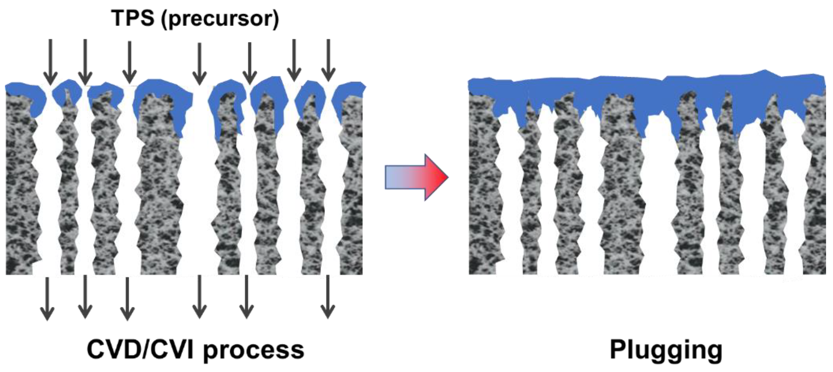
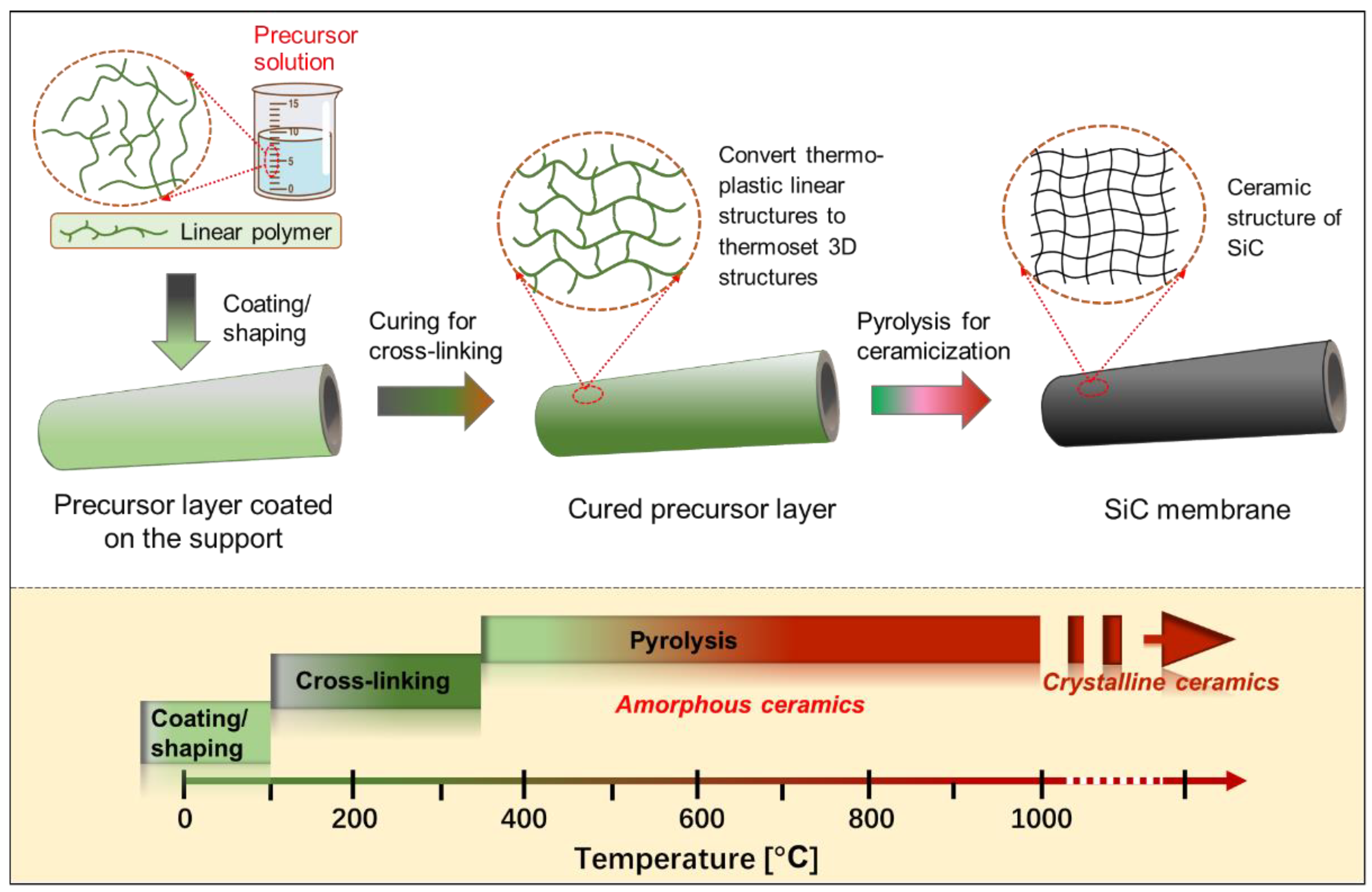
The scale of research for developing and applying silicon carbide (SiC) membranes for gas separation has rapidly expanded over the last few decades. The precursor-derived ceramic approaches for preparing SiC membranes include chemical vapor deposition (CVD)/chemical vapor infiltration (CVI) deposition and pyrolysis of polymeric precursor. Generally, SiC membranes formed using the CVD/CVI deposition route have dense structures, making such membranes suitable for small-molecule gas separation. On the contrary, pyrolysis of a polymeric precursor is the most common and promising route for preparing SiC membranes, which includes the steps of precursor selection, coating/shaping, curing for cross-linking, and pyrolysis. Among these steps, the precursor, curing method, and pyrolysis temperature significantly impact the final microstructures and separation performance of membranes.
1. Introduction
1.1. Membrane-Based Gas Separation
1.2. Inorganic Membranes
| Membrane Material | Amorphous Structure | Advantages | Disadvantages |
|---|---|---|---|
| Silica (SiO2) |  |
|
|
| Carbon molecular sieve (CMS) or carbon membranes |
 [12] [12] |
|
|
| Silicon carbide (SiC) |  |
|
|
2. Fabrication of SiC Membranes
| Shape and Pore Size of Supports | Raw Materials of Layers on Supports | Layer Deposition Method | Top Layer Thickness [μm] | Thermal Treatment | Pore Size (Type: MF, UF) | Applications and Other Remarks | Ref. | |
|---|---|---|---|---|---|---|---|---|
| Transition Layer | Top Layer | |||||||
| Disk, 15 μm | na. | α-SiC powder (10 μm), SiC whisker, methylcellulose (MC) 2, CaO 5, ZrO2 5, mullite 5, TL-56NQ 4, water 1 | Spray coating | 125 | 1150–1250 °C, 2 h in air; then 1350–1500 °C, 4 h in Ar | 2.31 μm (MF) |
|
[25] |
| Flat tube, 1.8 μm | na. | SiC powder (0.55 μm), IPA 1, PVA 3, PEG 3, Darvan-CN 2, water 1 | Dip-coating | 12–30 | 900–1300 °C, 1 h | 75–155 nm (MF) |
|
[26] |
| Flat tube, 34.92 μm | na. | SiC powder (22 µm), B4C 5, PVA 3, TMAOH 2, water | Dip-coating | ~100 | 2200–2250 °C | 9.93 μm (MF) |
|
[27] |
| Tube, 15 μm | na. | α-SiC powder (0.4 μm and 0.6 μm), Al(NO3)3·9H2O 5, Optapix CS-76 3, polysaccharide dicarbonic acid polymer 3, water 1 | Dip-coating | 27.3–29.4 | 1600–1900 °C | 0.35 μm (MF) |
|
[28] |
| Flat sheet, 5.6–14.1 μm | na. | SiC powders (0.5 µm and 3 µm), PAA 2, CMC 3, water 1 | Dip-coating | 60 | 1900–2000 °C in vacuum | 0.5 μm (1900 °C); 1.4 μm (2000 °C) (MF) |
|
[29] |
| Flat disk, <100 μm | Consisting of several SiC layers; pore diameter <300 nm |
α-SiC powder (0.4 µm), AHPCS 6, hexane 1, hexane/tetradecane 1 | Dip-coating | 10–19 | 200 °C, 1 h; 400 °C, 1 h; and then 750 °C, 2 h | <50 nm (UF) |
|
[30] |
| Tube/na. | SiC powder (0.6 µm), acetone; pore diameter =130 nm | PS 7, toluene 1, AHPCS 6, hexane 1 | Slip-casting + dip-coating |
7 | 200 °C, 1 h, 400 °C, 1 h, and then 750 °C, 2 h in Ar; 450 °C, 2 h in air | Nanoporous SiC membranes |
|
[31] |
2.1. Chemical Vapor Deposition/Infiltration Route
| Membranes | Precursor | Supports | Deposition Temperature | Ref. |
|---|---|---|---|---|
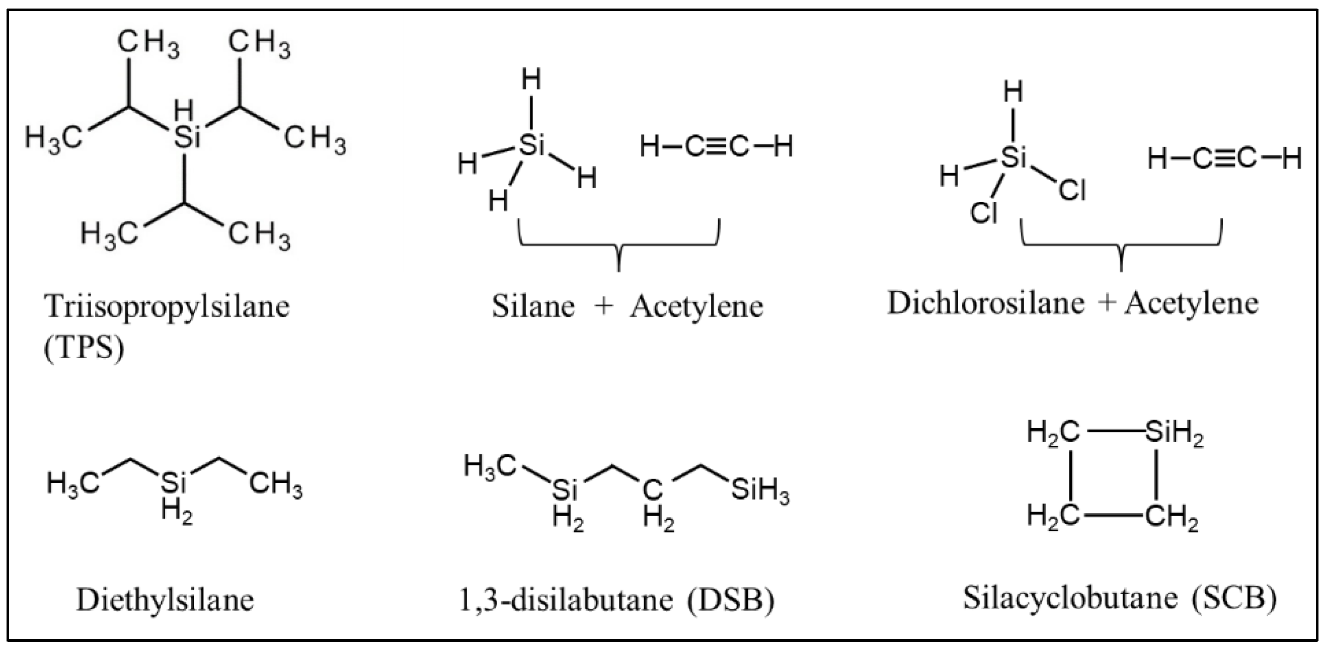
| SiCN | SiH4/C2H2/NH3 | α-Al2O3; disk | 1050 °C in Ar | [37] |
| SiCO | SiH2Cl2/C2H2/H2 | γ-Al2O3/α-Al2O3; tube | 800–900 °C in H2 | [38][39] |
| SiC | Triisopropylsilane (TPS) | SiC; disk; and tube | 760–800 °C in Ar/He | [36] |
| SiC | Silacyclobutane (SCB) | Ni-γ-Al2O3/α-Al2O3; tube | 515 °C in Ar | [40] |
| SiC | 1,3-disilabutane (DSB); TPS | α-Al2O3; γ-Al2O3/α-Al2O3; tube | TPS: 700–800 °C in He, and annealed at 1000 °C; DSB: 650–750 °C in He |
[41][42] |
2.2. Pyrolysis of the Polymeric Precursor Route
2.2.1. Si-Containing Precursors
The fabrication of SiC ceramics by the pyrolysis of a polymeric precursor process is strongly influenced by the chemistry and architecture of the Si-based preceramic precursors, their processing routes, and the parameters used for their pyrolysis. To be suitable for producing SiC ceramic materials, Si-based polymers must meet the following important requirements: (i) the polymers should have a sufficiently high molecular weight to avoid volatilization of components with low molecular weights during subsequent curing and pyrolysis processes; (ii) they should have appropriate rheological characteristics, as well as solubility for the coating/shaping process; (iii) they should have latent reactivity, provided by the presence of specific functional groups (e.g., Si–H, N–H, Si–OH, and Si–CH=CH2), which induce cross-linking during the curing process upon exposure to thermal stimuli, chemical stimuli, or irradiation (e.g., UV, electro-beam, and γ-ray).
2.2.2. Coating/Shaping
The quality of the coating/shaping depends on the deposition techniques and the solution properties of the precursors. Precursor coating methods mainly include dip-coating [44], wipe-coating [32], casting [31], spin-coating [45], spray-coating [25], and even three-dimensional (3D) printing [46]. Dip-coating and wipe-coating are the most frequently used methods for fabricating membranes because of their relative simplicity. An important factor affecting the coating layers is the viscosity (a rheological characteristic) of the coating solutions, which should be controlled carefully by changing the molecular architectures of the precursors, concentration, and solvent species to achieve coating layers with high quality. This is because the viscosity of the coating solutions could affect the thickness and uniformity of the membrane layers.
2.2.3. Curing and Pyrolysis Processes
Curing for Cross-Linking
The coated precursor typically requires to be cured at low temperatures (up to 300–400 °C) prior to pyrolysis [47][48], which plays an important role in determining the final quality of SiC ceramic materials, including their microstructural properties. The curing process of polymeric precursors for cross-linking converts the thermoplastic polymers into thermosetting polymers via a series of reactions, such as dehydrogenation and oxidation, which prevents the coating layers/shapes from fusing together during pyrolysis [49]. Additionally, curing is known to promote high ceramic yields of polymeric precursors because cross-linking prevents the volatilization of precursor components with low molecular weight at high temperatures. To date, several curing techniques have been carried out to produce SiC membranes, such as ultraviolet (UV) radiation, electron beam (EB)/γ-ray irradiation [50][51], and conventional thermal treatment under an oxidizing or inert atmosphere [52][53]. These curing techniques induce various condensation (dehydrogenation or demethanization) and addition reactions converting linear polymer networks to 3D polymer networks.
Pyrolysis for Polymer-To-Ceramic Conversion
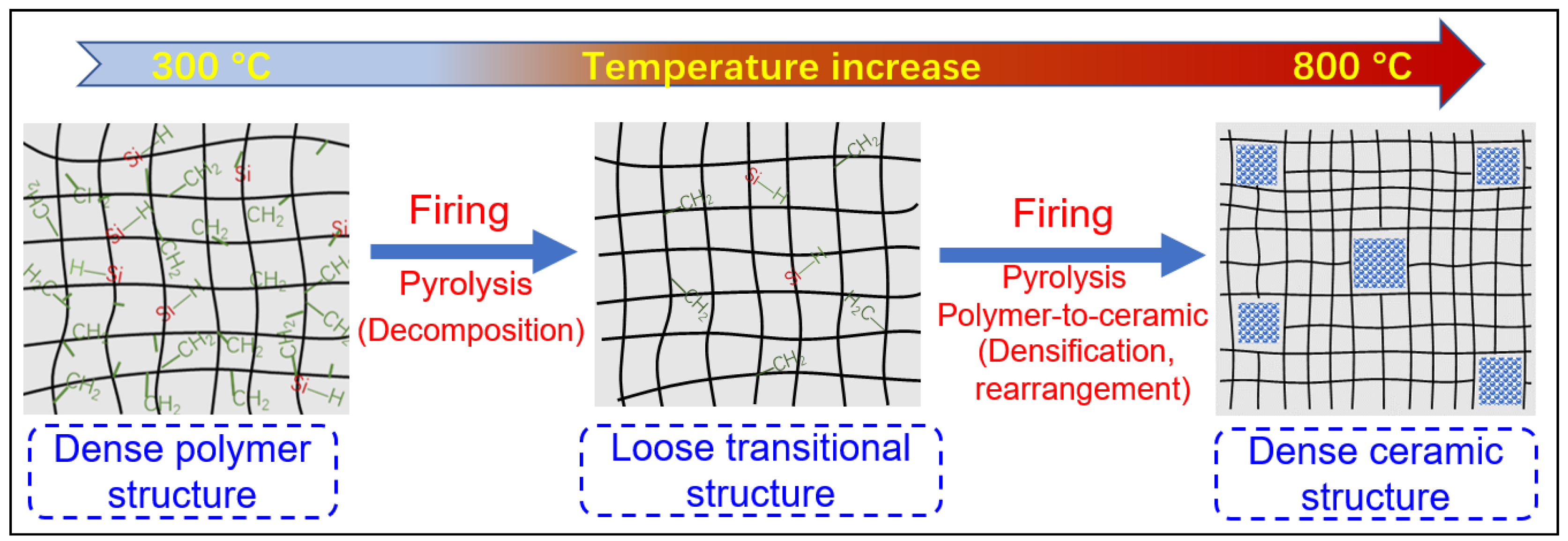
After curing for cross-linking, further thermal treatment at elevated temperatures (usually ≥300 °C) and under an inert atmosphere, i.e., pyrolysis, results in an organic-to-inorganic conversion (from thermoset polymers to amorphous SiC ceramics) [43][52]. This conversion is caused mainly by radicals, condensation (dehydrogenation and demethanization), and rearrangement reactions, which lead to the cleavage of chemical bonds and the formation of new bonds accompanied by the elimination of organic groups and the release of gases, such as H2, CH4, and C6H6 [32]. For most polymeric precursors, the conversion from polymeric precursor to amorphous ceramic is complete at <900 °C, followed by crystallization from the amorphous phase at higher temperatures (>1100 °C) and resulting in phase separation [32][47][52][54][55][56].
During the organic-to-inorganic ceramic transformation, the microstructure of polymeric precursors undergoes dramatic changes with increasing pyrolysis temperature [32]. As shown in Figure 6, the microporous properties and pore structure parameters (BET and micropore volume) of the pyrolytic precursor (polytitanocarbosilane, TiPCS) powders were analyzed by N2 adsorption–desorption isotherms [32]. The adsorption capacity, micropore volume, and BET surface area increased by firing from 500 °C to 650 °C and then decreased with increasing pyrolysis temperature from 650 °C to 1000 °C. It is worth noting that this is a general conclusion because PCS [55][57], polydimethylsilane (PMS) [58], and AHPCS [52] precursors follow the same trends within a similar pyrolysis temperature range of 300–850 °C. These trends suggest that the decomposition of organic groups generates many micropores at moderate temperatures and the micropores are then narrowed gradually as the pyrolysis temperature increases because of densification and rearrangement reactions.
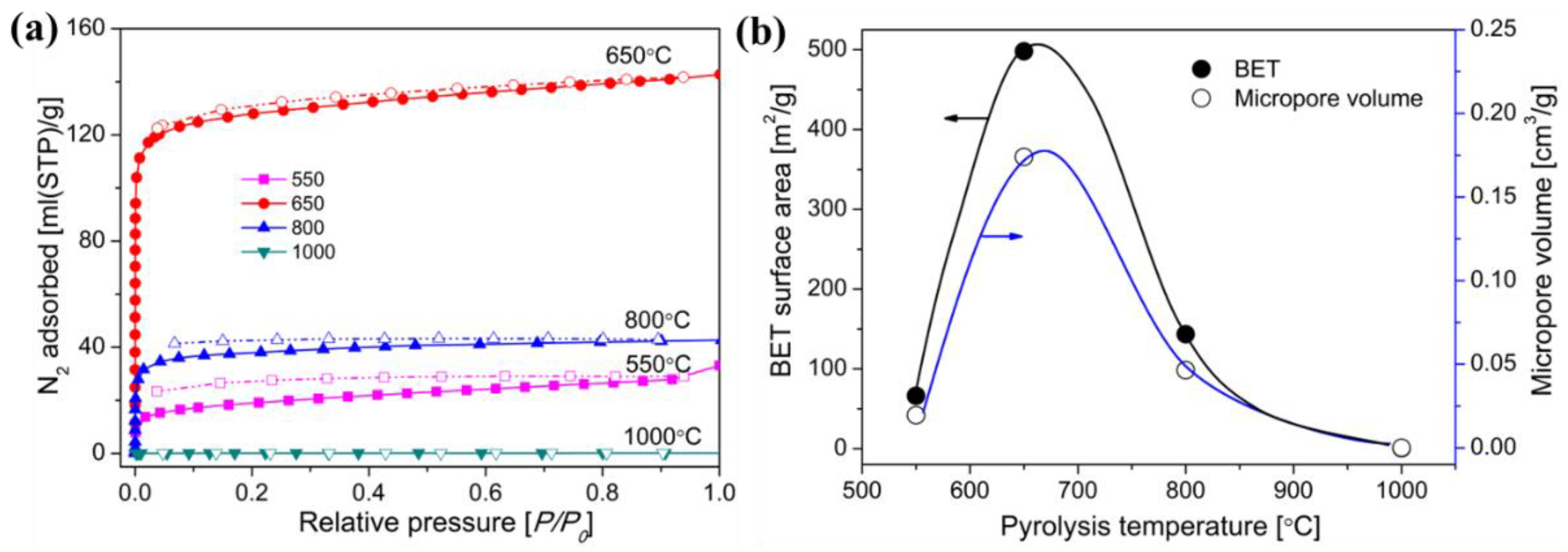
Figure 6. (a) N2 adsorption–desorption isotherms at 77 K, (b) BET surface area and micropore volume (at a relative pressure of P/P0 = 0.01, pore size ≤ 1 nm) of pyrolyzed precursor (TiPCS) powders. Adapted from [32] with permission from Elsevier.
References
- Logan, B.E.; Elimelech, M. Membrane-based processes for sustainable power generation using water. Nature 2012, 488, 313–319.
- Sholl, D.S.; Lively, R.P. Seven chemical separations to change the world. Nature 2016, 532, 435–437.
- Ezugbe, E.O.; Rathilal, S. Membrane Technologies in Wastewater Treatment: A Review. Membranes 2020, 10, 89.
- Voutchkov, N. Energy use for membrane seawater desalination—Current status and trends. Desalination 2018, 431, 2–14.
- Liang, C.Z.; Chung, T.-S.; Lai, J.-Y. A review of polymeric composite membranes for gas separation and energy production. Prog. Polym. Sci. 2019, 97, 101141.
- Liu, C.; Greer, D.W.; O’Leary, B.W. Advanced Materials and Membranes for Gas Separations: The UOP Approach. Nanotechnol. Deliv. Promise 2016, 2, 119–135.
- Bernardo, P.; Drioli, E.; Golemme, G. Membrane Gas Separation: A Review/State of the Art. Ind. Eng. Chem. Res. 2009, 48, 4638–4663.
- Valappil, R.S.K.; Ghasem, N.; Al-Marzouqi, M. Current and future trends in polymer membrane-based gas separation technology: A comprehensive review. J. Ind. Eng. Chem. 2021, 98, 103–129.
- Abdallah, H. A Review on Catalytic Membranes Production and Applications. Bull. Chem. React. Eng. Catal. 2017, 12, 136–156.
- Robeson, L.M. The upper bound revisited. J. Membr. Sci. 2008, 320, 390–400.
- Awasthi, K.; Choudhury, S.; Komber, H.; Simon, F.; Formanek, P.; Sharma, A.; Stamm, M. Functionalization of track-etched poly (ethylene terephthalate) membranes as a selective filter for hydrogen purification. Int. J. Hydrogen Energy 2014, 39, 9356–9365.
- Qiu, W.; Leisen, J.E.; Liu, Z.; Quan, W.; Koros, W.J. Key Features of Polyimide-Derived Carbon Molecular Sieves. Angew. Chem. Int. Ed. 2021, 60, 22322–22331.
- Baker, R.W. Membrane Technology and Applications, 3rd ed.; John Wiley & Sons: Hoboken, NJ, USA, 2012.
- Eray, E.; Candelario, V.M.; Boffa, V.; Safafar, H.; Østedgaard-Munck, D.N.; Zahrtmann, N.; Kadrispahic, H.; Jørgensen, M.K. A roadmap for the development and applications of silicon carbide membranes for liquid filtration: Recent advancements, challenges, and perspectives. Chem. Eng. J. 2021, 414, 128826.
- Jafari, B.; Rezaei, E.; Abbasi, M.; Hashemifard, S.A.; Sillanpää, M. Application of mullite-zeolite-alumina microfiltration membranes coated by SiO2 nanoparticles for separation of oil-in-water emulsions. J. Eur. Ceram. Soc. 2022, 42, 6005–6014.
- Hotza, D.; Di Luccio, M.; Wilhelm, M.; Iwamoto, Y.; Bernard, S.; da Costa, J.C.D. Silicon carbide filters and porous membranes: A review of processing, properties, performance and application. J. Membr. Sci. 2020, 610, 118193.
- Pendergast, M.M.; Hoek, E.M. A review of water treatment membrane nanotechnologies. Energy Environ. Sci. 2011, 4, 1946–1971.
- Yang, Z.; Zhou, Y.; Feng, Z.; Rui, X.; Zhang, T.; Zhang, Z. A Review on Reverse Osmosis and Nanofiltration Membranes for Water Purification. Polymers 2019, 11, 1252.
- Yamamoto, K.; Sakai, T. Effect of Pore Structure on Soot Deposition in Diesel Particulate Filter. Computation 2016, 4, 46.
- Xu, C.; Xu, C.; Han, F.; Zhang, F.; Wei, W.; Zhong, Z.; Xing, W. Fabrication of high performance macroporous tubular silicon carbide gas filters by extrusion method. Ceram. Int. 2018, 44, 17792–17799.
- Dong, B.; Min, Z.; Guan, L.; Zheng, X.; Wang, L.; Wang, Q.; Yin, C.; Wang, Y.; Zhang, R.; Wang, F.; et al. Porous mullite-bonded SiC filters prepared by foaming-sol-gel-tape casting for high-efficiency hot flue gas filtration. Sep. Purif. Technol. 2022, 295, 121338.
- Fontão, N.C.; Wilhelm, M.; Rezwan, K. Asymmetric polysiloxane-based SiOC membranes produced via phase inversion tape casting process. Mater. Des. 2020, 198, 109328.
- Gubernat, A.; Zych, Ł.; Wierzba, W. SiC products formed by slip casting method. Int. J. Appl. Ceram. Technol. 2015, 12, 957–966.
- Deng, W.; Yu, X.; Sahimi, M.; Tsotsis, T.T. Highly permeable porous silicon carbide support tubes for the preparation of nanoporous inorganic membranes. J. Membr. Sci. 2014, 451, 192–204.
- Wei, W.; Zhang, W.; Jiang, Q.; Xu, P.; Zhong, Z.; Zhang, F.; Xing, W. Preparation of non-oxide SiC membrane for gas purification by spray coating. J. Membr. Sci. 2017, 540, 381–390.
- Bukhari, S.Z.A.; Ha, J.-H.; Lee, J.; Song, I.-H. Oxidation-bonded SiC membrane for microfiltration. J. Eur. Ceram. Soc. 2018, 38, 1711–1719.
- Liu, J.; Tian, C.; Xiao, H.; Guo, W.; Gao, P.; Liang, J. Effect of B4C on co-sintering of SiC ceramic membrane. Ceram. Int. 2018, 45, 3921–3929.
- Eray, E.; Candelario, V.M.; Boffa, V. Ceramic Processing of Silicon Carbide Membranes with the Aid of Aluminum Nitrate Nonahydrate: Preparation, Characterization, and Performance. Membranes 2021, 11, 714.
- Li, S.; Wei, C.; Zhou, L.; Wang, P.; Xie, Z. Evaporation-condensation derived silicon carbide membrane from silicon carbide particles with different sizes. J. Eur. Ceram. Soc. 2019, 39, 1781–1787.
- König, K.; Boffa, V.; Buchbjerg, B.; Farsi, A.; Christensen, M.L.; Magnacca, G.; Yue, Y. One-step deposition of ultrafiltration SiC membranes on macroporous SiC supports. J. Membr. Sci. 2014, 472, 232–240.
- Elyassi, B.; Sahimi, M.; Tsotsis, T.T. A novel sacrificial interlayer-based method for the preparation of silicon carbide membranes. J. Membr. Sci. 2008, 316, 73–79.
- Wang, Q.; Kawano, Y.; Yu, L.; Nagasawa, H.; Kanezashi, M.; Tsuru, T. Development of high-performance sub-nanoporous SiC-based membranes derived from polytitanocarbosilane. J. Membr. Sci. 2020, 598, 117688.
- Besmann, T.M.; Stinton, D.P.; Lowden, R.A.; Lee, W.Y. Chemical Vapor Deposition (CVD) and Infiltration (CVI). In Carbide, Nitride and Boride Materials Synthesis and Processing; Springer: Dordrecht, The Netherlands, 1997; pp. 547–577.
- Carlsson, J.-O.; Martin, P.M. Chemical vapor deposition. In Handbook of Deposition Technologies for Films and Coatings; Elsevier: Amsterdam, The Netherlands, 2010; pp. 314–363.
- Pierson, H.O. Introduction and general considerations. In Handbook of Chemical Vapor Deposition (CVD); William Andrew Inc.: Norwich, NY, USA, 1992; p. 2.
- Chen, F.; Mourhatch, R.; Tsotsis, T.T.; Sahimi, M. Experimental studies and computer simulation of the preparation of nanoporous silicon-carbide membranes by chemical-vapor infiltration/chemical-vapor deposition techniques. Chem. Eng. Sci. 2008, 63, 1460–1470.
- Hong, L.-S.; Lai, H.-T. Pore Structure Modification of Alumina Support by SiC− Si3N4 Nanoparticles Prepared by the Particle Precipitation Aided Chemical Vapor Deposition. Ind. Eng. Chem. Res. 1999, 38, 950–957.
- Nagano, T.; Sato, K.; Fujisaki, S.; Saitoh, T.; Iwamoto, Y. Helium-Permselective Amorphous SiC Membrane Modified by Chemical Vapor Infiltration. Soft Mater. 2007, 4, 109–122.
- Takeda, Y.; Shibata, N.; Kubo, Y. SiC coating on porous γ-Al2O3 using alternative-supply CVI method. J. Ceram. Soc. Jpn. 2001, 109, 305–309.
- Nagano, T.; Sato, K.; Kawahara, K. Gas Permeation Property of Silicon Carbide Membranes Synthesized by Counter-Diffusion Chemical Vapor Deposition. Membranes 2020, 10, 11.
- Sea, B.-K.; Ando, K.; Kusakabe, K.; Morooka, S. Separation of hydrogen from steam using a SiC-based membrane formed by chemical vapor deposition of triisopropylsilane. J. Membr. Sci. 1998, 146, 73–82.
- Ciora, R.J.; Fayyaz, B.; Liu, P.K.; Suwanmethanond, V.; Mallada, R.; Sahimi, M.; Tsotsis, T.T. Preparation and reactive applications of nanoporous silicon carbide membranes. Chem. Eng. Sci. 2004, 59, 4957–4965.
- Barroso, G.; Li, Q.; Bordia, R.K.; Motz, G. Polymeric and ceramic silicon-based coatings—A review. J. Mater. Chem. A 2019, 7, 1936–1963.
- Dabir, S.; Deng, W.; Sahimi, M.; Tsotsis, T. Fabrication of silicon carbide membranes on highly permeable supports. J. Membr. Sci. 2017, 537, 239–247.
- Kim, Y.H.; Kim, E.B.; Kim, S.R.; Suh, M.H.; Choi, D.J.; Kwon, W.T. Hydrogen Separation Characteristics of SiC Nanoporous Membrane at High Temperature. Adv. Mater. Res. 2007, 26, 271–274.
- Li, X.; Pei, X.; Zhong, X.; Mo, G.; He, L.; Huang, Z.; Huang, Q. Highly effective free-radical-catalyzed curing of hyperbranched polycarbosilane for near stoichiometric SiC ceramics. J. Am. Ceram. Soc. 2018, 102, 1041–1048.
- Wang, Q.; Xu, N.; Liu, Q.; Dong, Q.; Nagasawa, H.; Kanezashi, M.; Zhou, R.; Tsuru, T. Low-temperature cross-linking fabrication of sub-nanoporous SiC-based membranes for application to the pervaporation removal of methanol. J. Membr. Sci. 2022, 662, 121008.
- Li, H.; Zhang, L.; Cheng, L.; Wang, Y.; Yu, Z.; Huang, M.; Tu, H.; Xia, H. Effect of the polycarbosilane structure on its final ceramic yield. J. Eur. Ceram. Soc. 2008, 28, 887–891.
- Hong, J.; Cho, K.-Y.; Shin, D.-G.; Kim, J.-I.; Riu, D.-H. Iodine diffusion during iodine-vapor curing and its effects on the morphology of polycarbosilane/silicon carbide fibers. J. Appl. Polym. Sci. 2015, 132, 42687.
- Wach, R.A.; Sugimoto, M.; Yoshikawa, M. Formation of Silicone Carbide Membrane by Radiation Curing of Polycarbosilane and Polyvinylsilane and its Gas Separation up to 250 °C. J. Am. Ceram. Soc. 2006, 90, 275–278.
- Takeyama, A.; Sugimoto, M.; Yoshikawa, M. Gas Permeation Property of SiC Membrane Using Curing of Polymer Precursor Film by Electron Beam Irradiation in Helium Atmosphere. Mater. Trans. 2011, 52, 1276–1280.
- Wang, Q.; Yokoji, M.; Nagasawa, H.; Yu, L.; Kanezashi, M.; Tsuru, T. Microstructure evolution and enhanced permeation of SiC membranes derived from allylhydridopolycarbosilane. J. Membr. Sci. 2020, 612, 118392.
- Li, Y.-L.; Fan, H.; Su, D.; Fasel, C.; Riedel, R. Synthesis, Structures, and Properties of Bulk Si(O)C Ceramics from Polycarbosilane. J. Am. Ceram. Soc. 2009, 92, 2175–2181.
- Yu, X.; Wang, Q.; Nagasawa, H.; Kanezashi, M.; Tsuru, T. SiC mesoporous membranes for sulfuric acid decomposition at high temperatures in the iodine–sulfur process. RSC Adv. 2020, 10, 41883–41890.
- Wang, Q.; Yu, L.; Nagasawa, H.; Kanezashi, M.; Tsuru, T. Tuning the microstructure of polycarbosilane-derived SiC(O) separation membranes via thermal-oxidative cross-linking. Sep. Purif. Technol. 2020, 248, 117067.
- Wang, Q.; Yu, L.; Nagasawa, H.; Kanezashi, M.; Tsuru, T. High-performance molecular-separation ceramic membranes derived from oxidative cross-linked polytitanocarbosilane. J. Am. Ceram. Soc. 2020, 103, 4473–4488.
- Maddocks, A.R.; Cassidy, D.J.; Jones, A.S.; Harris, A.T. Synthesis of nanoporous silicon carbide via the preceramic polymer route. Mater. Chem. Phys. 2009, 113, 861–867.
- Lee, L.-L.; Tsai, D.-S. Synthesis and Permeation Properties of Silicon−Carbon-Based Inorganic Membrane for Gas Separation. Ind. Eng. Chem. Res. 2000, 40, 612–616.

