Fabrication of SiC Membranes: Comparison
Please note this is a comparison between Version 1 by Qing Wang and Version 3 by Qing Wang.

The scale of research for developing and applying silicon carbide (SiC) membranes for gas separation has rapidly expanded over the last few decades. The precursor-derived ceramic approaches for preparing SiC membranes include chemical vapor deposition (CVD)/chemical vapor infiltration (CVI) deposition and pyrolysis of polymeric precursor. Generally, SiC membranes formed using the CVD/CVI deposition route have dense structures, making such membranes suitable for small-molecule gas separation. On the contrary, pyrolysis of a polymeric precursor is the most common and promising route for preparing SiC membranes, which includes the steps of precursor selection, coating/shaping, curing for cross-linking, and pyrolysis. Among these steps, the precursor, curing method, and pyrolysis temperature significantly impact the final microstructures and separation performance of membranes. Ref.

  • silicon carbide membrane
  • gas separation
  • precursor-derived ceramics
  • polycarbosilane
  • allyl-hydridopolycarbosilan
  • CVD/CVI
  • pyrolysis
  • organic to inorganic transformation

1. Introduction

With rapid economic development, separation and purification processes are used widely in industrial production and daily life, and their requirements are increasing [1]. However, separating bulk mixtures into pure or purer forms incurs high costs. For example, the current market heavily relies on traditional separation processes and energy-intensive separation methods, such as distillation, which accounts for approximately 10%–15% of global energy consumption [2]. Note that 10 × 107 tons of CO2 emissions and USD 4 billion in energy costs could be saved annually if more energy-efficient separation approaches were used in the United States alone. Therefore, ever-increasing industrialization requires more efficient, economical, and sustainable separation and purification technologies. Membrane separation techniques are favored because of their advantages, such as low energy consumption, no need for additives, small footprint, and easy scale-up. Additionally, membrane separation techniques are potential candidates to replace traditional thermal-based separation methods. They are powerful tools for solving critical global problems and for developing new industrial processes required for sustainable industrial growth.

1.1. Membrane-Based Gas Separation

Currently, membrane applications mainly involve aqueous media such as wastewater treatment [3], seawater desalination [4], and gaseous media such as air separation, hydrogen production, natural gas purification, and CO2 capture [5]. The separation/purification of aqueous media using membranes has been studied extensively and applied successfully in various industries, and membranes were applied for gas separation later than for aqueous media. In 1980, Permea (Monsanto) commercialized Prism membranes for industrial applications in separating hydrogen from purge gas streams of ammonia plants, thus marking the beginning of the first large-scale industrial application of gas separation membranes [6]. Since then, membranes for gas separation have attracted considerable attention from industry and academia, and membrane-based gas separation has exponentially grown.
Membrane-based gas separation does not require phase changes, whereas conventional separation technologies such as adsorption and cryogenic distillation require phase changes with significant energy costs [7]. Generally, permeability (e.g., permeance and flux) and selectivity (or separation factor) are two common and fundamental membrane performance characteristics. The ideal membrane should exhibit high permeability and selectivity. Higher permeability reduces the required membrane area for processing a given amount of gas, thereby reducing the investment cost of membranes. Higher selectivity will result in high-purity gas products. Based on current requirements for advanced membrane technology, achieving the successful application of membranes in gas separation processes not only depends on the high permselectivity of membranes but also on the selection of membrane materials with thermal, hydrothermal, chemical, and mechanical stability [8].

1.2. Inorganic Membranes

Membranes can be roughly classified into polymeric and inorganic membranes according to the nature of their fabrication material. Polymeric membranes hold the largest market share and have attracted great interest in commercial-scale applications and academic research. This is mainly due to the economic feasibility of raw materials and convenient membrane manufacture [9]. However, exposing polymers to hydrocarbons or carbon dioxide under high partial pressures could lead to swelling or plasticization, resulting in a significant decrease or loss of separation capacity. Polymeric membranes fall short of the requirements of current advanced membrane technologies as they exhibit a trade-off between permeability and selectivity, with a distinct “upper limit” proposed by Robeson [10][11][10,11]. In addition, polymeric membranes cannot withstand aggressive chemical environments and high temperatures.
Compared to polymeric membranes, inorganic membranes have many advantages, such as high chemical, thermal, and mechanical stability. Inorganic membranes have been fabricated from crystalline materials such as zeolites, metal-organic frameworks (MOFs), and amorphous materials. In particular, amorphous inorganic membranes, such as silica, carbon molecular sieves, and silicon carbide-based membranes, also feature better control of pore size and size distribution, as summarized in Table 1. This pore-size control allows for better control of permeability and selectivity.
Table 1.
Advantages and disadvantages of inorganic membranes with amorphous structures.
Membrane Material Amorphous Structure Advantages Disadvantages
Silica (SiO2) Membranes 12 01255 i001
  • Good thermal stability at moderate temperatures
  • Controllability of pore sizes from the sub-nano to several nanometer range
  • High separation performance for small-sized gases (e.g., H2)
  • Low-level hydrothermal stability
  • Easy sintering at higher temperatures
Carbon molecular sieve (CMS)

or

carbon membranes
Membranes 12 01255 i002 [12]
  • Excellent chemical stability
  • Rich ultra-micropores
  • Ability to distinguish molecules of almost the same size
  • Surpass the trade-off for gas separation (especially for hydrocarbons)
  • Instability in the presence of water vapor
  • High cost of polymeric precursors (e.g., polyimide)
  • Limited oxidation resistance (enlarge or destroy the membrane pores)
  • Brittle, difficult to scale-up
Silicon carbide (SiC) Membranes 12 01255 i003
  • Have excellent chemical, mechanical, and hydrothermal stability; high oxidation resistance
  • Simple fabrication process; easy to scale-up
  • Membranes with controlled structures
  • Wide range of applications for filters (MF, UF, NF, and RO) and gas separation
  • Multiple-layer coatings
  • High cost of polymeric precursors
Amorphous structure of CMS adapted from Ref. [12] with permission.

2. Fabrication of SiC Membranes

SiC membranes can be divided according to their morphological construction into symmetrical and asymmetrical types, as shown in Figure 12 [13][38]. Relatively high permeation fluxes can be obtained via asymmetric membranes, which consist of a support, transition layers (e.g., a particle layer and/or an intermediate layer), and a separation layer. The supports without separation layers, also known as membrane substrates, play an important role in producing defect-free and reproducible separation layers, which in turn play an important role in meeting industrial demand. The membrane substrates should have good characteristics to provide high flux, porosity, and mechanical strength. Currently, materials used as substrates are mainly alumina, mullite, titania, zirconia, SiC, and their composites [14][15][35,39]. Among them, SiC is a promising material for fabricating membrane substrates due to its unique properties. Generally, the same SiC substrates can be used as membrane filters, e.g., for microfiltration (MF, 0.05–10 μm), ultrafiltration (UF, 2–50 nm), and nanofiltration (NF, ≤2 nm) [16][17][18][37,40,41]. SiC supports/filters with large pores (>10 μm) are commonly used for air filtering, soot filtering, and catalyst distributors in diesel engines [16][19][37,42]. Processing methods for these supports/filters, such as extrusion [20][43], tape casting [21][22][44,45], slip-casting [23][46], and compression molding [24][47], have been extensively investigated.
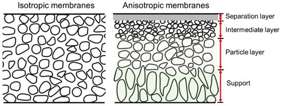
Figure 12. Schematic of isotropic and anisotropic membranes [13].
Schematic of isotropic and anisotropic membranes [38].
SiC membrane filters usually consist of multiple layers on macroporous supports. Depending on their application purpose, the layers can be designed to generate an upper layer with suitable pore sizes. SiC membrane filters are used mainly in pressure-driven processes, such as MF, UF, and NF, and they have found applications in water treatment, food, and gas cleaning industries. There are a variety of fabrication processes for the fabrication of SiC membrane filters with respect to support characteristics, the range of combinations of raw materials (such as SiC powder compositions, particle sizes, polymer precursors, and sintering additives), deposition techniques, thermal treatment, and applications, as listed in Table 12. The thickness of the top layers ranged from 7 to 125 µm, and the layers were sintered at temperatures up to 2250 °C (Table 12). It is worth noting that the thickness of the top layers (7–19 µm) with transition layers (intermediate layers) was considerably thinner than the top layers directly produced on supports because the transition layers prevent the top-layer solutions from permeating the supports. Additionally, the use of preceramic precursors (e.g., allyl-hydridopolycarbosilane, AHPCS) reduced the thermal treatment temperature significantly to 750 °C, reducing the SiC membrane production cost.
Table 12.
Fabrication process and properties of representative SiC membrane filtrations (MF and UF).
Shape and Pore Size of Supports Raw Materials of Layers on Supports Layer Deposition Method Top Layer Thickness [μm] Thermal Treatment Pore Size (Type: MF, UF) Applications and Other Remarks Ref.
Transition Layer Top Layer
Disk, 15 μm na. α-SiC powder (10 μm), SiC whisker, methylcellulose (MC) 2, CaO 5, ZrO2 5, mullite 5, TL-56NQ 4, water 1 Spray coating 125 1150–1250 °C, 2 h in air; then 1350–1500 °C, 4 h in Ar 2.31 μm (MF)
Figure 23. Schematic of SiC membrane preparation via the CVD/CVI deposition process. Adapted from [36] with permission from Elsevier.
Schematic of SiC membrane preparation via the CVD/CVI deposition process. Adapted from [59] with permission from Elsevier.
Figure 34.
Structures of typical precursors used in CVD/CVI techniques.
Table 23.
Representative processing parameters of SiC membranes obtained by CVD/CVI techniques.
Membranes Precursor Supports Deposition Temperature Ref.
SiCN SiH4/C2H2/NH3 α-Al2O3; disk 1050 °C in Ar [37][60]
  • Hot gas filtration (high permeability, dust removal efficiency, 99.95%)
  • Excellent corrosion resistance in both H2SO4 and NaOH
  • Excellent thermal shock resistance
[25][48]
Flat tube, 1.8 μm
SiCOna. SiH2Cl2/C2H2/H2SiC powder (0.55 μm), IPA 1, PVA 3, PEG 3, Darvan-CN 2, water γ-Al21 ODip-coating 12–30 3900–1300 °C, 1 h 75–155 nm (MF) /α-Al2O3; tube
  • Water filtration (high purity water permeance)
  • Crack-free oxidation-bonded SiC membranes
[ 800–900 °C in H2 [38][39][61,26][49]
62] Flat tube, 34.92 μm na. SiC powder (22 µm), B4C 5, PVA 3, TMAOH 2, water Dip-coating ~100 2200–2250 °C 9.93 μm (MF)
SiC Triisopropylsilane (TPS) SiC; disk; and tube 760–800 °C in Ar/He [36][59]
  • Gas filtration
  • SiC membranes prepared by co-sintering process
  • Good mechanical properties
[27][50]
Tube, 15 μm na. α-SiC powder (0.4 μm and 0.6 μm), Al(NO3)3·9H2O 5, Optapix CS-76 3, polysaccharide dicarbonic acid polymer 3, water 1
SiCDip-coating 27.3–29.4 1600–1900 °C 0.35 μm (MF) Silacyclobutane (SCB) Ni-γ-Al2O3/α-Al2O3; tube 515 °C in Ar [40][63]
  • Oily wastewater treatment (remarkable separation performance)
  • Multi-channeled tubular membranes
  • High chemical and mechanical stability
[28][51]
Flat sheet, 5.6–14.1 μm na. SiC powders (0.5 µm and 3 µm), PAA 2, CMC 3, water 1 Dip-coating 60 1900–2000 °C in vacuum 0.5 μm (1900 °C);

1.4 μm (2000 °C) (MF)
Dip-coating 10–19 200 °C, 1 h; 400 °C, 1 h; and then 750 °C, 2 h <50 nm (UF)
  • Water filtration
  • Nearly defect-free SiC membrane for UF applications
  • Complex pore structure
[30][53]
Tube/na. SiC powder (0.6 µm), acetone; pore diameter =130 nm PS 7, toluene 1, AHPCS 6, hexane 1 Slip-casting

+

dip-coating
7 200 °C, 1 h, 400 °C, 1 h, and then 750 °C, 2 h in Ar; 450 °C, 2 h in air Nanoporous SiC membranes
  • Gas separation
  • Polystyrene sacrificial interlayers
  • Improved membrane performance due to the sacrificial interlayers
[31][54]
Superscript notation: 1 = solvent; 2 = dispersant; 3 = binder; 4 = defoaming agent; 5 = sintering additive; 6 = polymeric precursor; 7 = pore former.
Currently, commercialized SiC membranes are mainly used in MF and UF applications. Regardless of the manufacturer, commercial SiC membranes with high permeability (or flux) and good rejection are used widely in water treatment, especially for MF applications [14][32][35,55]. Although the commercial-scale production of SiC membranes is already a mature technology, manufacturing membranes with smaller pore sizes and narrower pore size distributions is a major challenge, such as for water treatment via NF and RO, and particularly for gas separation using microporous SiC membranes. In recent decades, extensive research has been conducted on the preparation of microporous SiC membranes with productive achievements. The subsequent sections focus on the two main precursor/polymer-derived ceramic approaches for fabricating SiC membranes, namely CVD/CVI and the pyrolysis of preceramic precursors.

2.1. Chemical Vapor Deposition/Infiltration Route

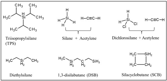
CVD/CVI involves exposing a heated substrate to one or more volatile precursors (e.g., organosilica) that react or decompose on the substrate surface (or on the pore walls) to deposit the desired thin film [33][34][56,57]. CVD/CVI is a versatile process for manufacturing coatings/films, fibers, powders, and monolithic components [35][58]. During the formation of SiC membranes, a schematic diagram of the phenomena that could occur via the CVD/CVI deposition process is shown in Figure 23. The precursor (e.g., triisopropylsilane, TPS) is carried by the carrier gas (e.g., Ar) into the pore space of the support, where it reacts to form SiC on the pore surface. SiC gradually shrinks/plugs the pores (especially the macropores) and forms a dense membrane layer [36][59]. Table 23 lists the representative processing parameters of the SiC membranes obtained by CVD/CVI techniques using the typical precursors shown in Figure 34. It is worth noting that the vast majority of support materials used to fabricate inorganic membranes, as well as SiC membranes, are α-Al2O3. This is due mainly to the ease of commercialization and high economic competitiveness of α-Al2O3.
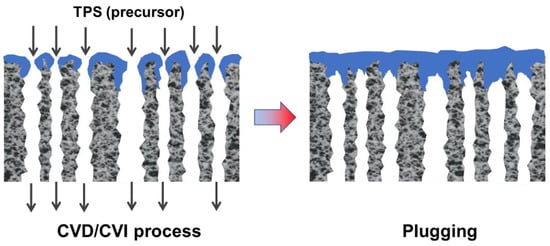
SiC
1,3-disilabutane (DSB); TPS
α-Al2O3; γ-Al2O3/α-Al2O3; tube TPS: 700–800 °C in He, and annealed at 1000 °C;

DSB: 650–750 °C in He
[41][42][64,65
  • Gas filtration
  • Homogeneous structure
[29][52]
] Flat disk, <100 μm Consisting of several SiC layers;

pore diameter <300 nm
α-SiC powder (0.4 µm), AHPCS 6, hexane 1, hexane/tetradecane 1
In an early effort, Hong et al. used the SiH4/C2H2/NH3 reaction system and α-Al2O3 supports to fabricate SiC membranes using hot-wall CVD [37][60]. SiC-Si3N4 nanoparticles were formed in the gas phase at 1050 °C and deposited in/on the support macropores to form a separation layer with an average pore size of 0.21 μm, which indicates that membrane pore sizes were still in the MF range. Takeda et al. reported the preparation of SiC membranes on γ-Al2O3-coated tubular α-Al2O3 supports via CVI using the SiH2Cl2/C2H2/H2 reaction system at 800–900 °C [39][62]. The final SiC membranes exhibited H2 permeances of 1 × 10⁻⁸ mol/(m2 s Pa) with an H2/N2 selectivity of 3.36 (Knudsen selectivity of 3.74) at 350 °C. Sea et al. reported pure SiC membranes prepared using triisopropylsilane (TPS) on the macropores of tubular α-Al2O3 supports using CVD at 700–800 °C, followed by calcination in Ar at 1000 °C [41][64]. However, these membranes exhibited a Knudsen-type diffusion mechanism without selectivity toward H2. Ciora and Tsotsis et al. were the first to report the fabrication of truly microporous SiC membranes on γ-Al2O3-coated tubular α-Al2O3 supports via a CVD/CVI technique using two different precursors (i.e., 1,3-disilabutane (DSB) and TPS) [42][65]. In their study, the TPS-derived membranes with He permeance ranging from 8.06 × 10⁻⁸ to 1.72 × 10⁻⁶ mol/(m2 s Pa) and He/N2 selectivity ranging from 4 to >100 at 550 °C were hydrothermally stable in the presence of high-pressure (1–3 bar) steam. However, DSB-derived versions with He permeance of 3.5 × 10⁻⁷ mol/(m2 s Pa) and He/N2 selectivity of ~55 at 550 °C were not. The preparation procedure of membranes using TPS involved multiple steps that required post-treatment for further structural tailoring at temperatures reaching 1000 °C, which increases the cost. Nagano et al. successfully synthesized a helium-selective SiC membrane on the outer surface of a γ-Al2O3-coated tubular α-Al2O3 support by the pyrolysis of polycarbosilane (PCS) at 800 °C under Ar and then modified by CVI using the SiH2Cl2/C2H2/H2 reaction system [38][61]. Compared to the original membrane, the membrane modified by CVI exhibited increased He/CO2 selectivity from 7.7 to 64 and increased He/H2 selectivity from 1.1 to 4.4. However, the He permeance significantly decreased from 8.9 × 10⁻⁷ to 7.7 × 10⁻⁸ mol/(m2 s Pa) at 600 °C. The authors attributed this to the densification of the Si-C network and the plugging of surface defects during CVI modification. Most recently, Nagano et al. synthesized amorphous SiC membranes on Ni-γ- Al2O3/Al2O3 supports by counter-diffusion CVD at 515 °C using silacyclobutane and Ar as the carrier gas [40][63]. As shown in Figure 45, the membrane possessed an H2 permeance of 1.2 × 10⁻⁷ mol/(m2 s Pa) and excellent H2/CO2 selectivity of 2600 at 400 °C at a deposition time of 9 min. The SiC layers were formed within minutes by the CVD/CVI deposition process, which improves the production efficiency of SiC membranes significantly from an industrial point of view. However, as mentioned above, a major issue that remains to be resolved is that SiC membranes formed using CVD/CVI deposition techniques possess dense structures, resulting in low permeability as well as high selectivity suitable for small-molecule gas separation, such as He/H2 and H2/CO2. However, such membranes may not be suitable for separating small-to-mid-sized molecules from larger ones.
Figure 45. Single-gas permeance of SiC membranes formed by the CVD deposition process. Reprinted from [40] with permission.
Single-gas permeance of SiC membranes formed by the CVD deposition process. Reprinted from [63] with permission.

2.2. Pyrolysis of the Polymeric Precursor Route

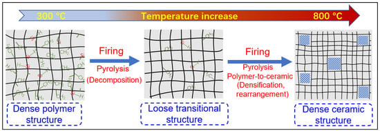
Another well-known method for preparing SiC membranes is the pyrolysis of coated polymeric precursors. The greatest advantage of this method over the CVD/CVI technique is its processing simplicity, low thermal treatment (pyrolysis) temperatures (≤850 °C), and the fact that production can be carried out either continuously or in a batch process. Furthermore, the preceramic polymeric precursor approach features significant advantages in manufacturing membranes with controlled properties and structures, such as composition, hydrophilic/hydrophobic properties, and pore size, which ultimately affect SiC membrane performance. Figure 56 presents a general schematic of the pyrolysis of the preceramic precursor for manufacturing SiC membranes. In particular, the employed polymeric precursors generally undergo three steps using this route to form SiC membranes, depending on the temperature (these steps are shown at the bottom of Figure 56): coating/shaping, curing for cross-linking, and pyrolysis under an inert atmosphere to complete the polymer-to-ceramic conversion [43][66]. In this multi-step process, each step is important for obtaining high-quality membranes.
Figure 56. Schematic of pyrolysis for the preceramic precursor route to manufacture SiC membranes. These steps are also temperature dependent and are shown at the bottom.

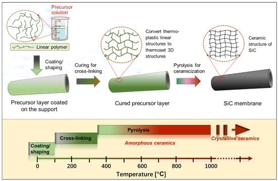
2.2.1. Si-Containing Precursors

The fabrication of SiC ceramics by the pyrolysis of a polymeric precursor process is strongly influenced by the chemistry and architecture of the Si-based preceramic precursors, their processing routes, and the parameters used for their pyrolysis. To be suitable for producing SiC ceramic materials, Si-based polymers must meet the following important requirements: (i) the polymers should have a sufficiently high molecular weight to avoid volatilization of components with low molecular weights during subsequent curing and pyrolysis processes; (ii) they should have appropriate rheological characteristics, as well as solubility for the coating/shaping process; (iii) they should have latent reactivity, provided by the presence of specific functional groups (e.g., Si–H, N–H, Si–OH, and Si–CH=CH2), which induce cross-linking during the curing process upon exposure to thermal stimuli, chemical stimuli, or irradiation (e.g., UV, electro-beam, and γ-ray).

2.2.2. Coating/Shaping

The quality of the coating/shaping depends on the deposition techniques and the solution properties of the precursors. Precursor coating methods mainly include dip-coating [44][31], wipe-coating [32][55], casting [31][54], spin-coating [45][80], spray-coating [25][48], and even three-dimensional (3D) printing [46][81]. Dip-coating and wipe-coating are the most frequently used methods for fabricating membranes because of their relative simplicity. An important factor affecting the coating layers is the viscosity (a rheological characteristic) of the coating solutions, which should be controlled carefully by changing the molecular architectures of the precursors, concentration, and solvent species to achieve coating layers with high quality. This is because the viscosity of the coating solutions could affect the thickness and uniformity of the membrane layers.

2.2.3. Curing and Pyrolysis Processes

Curing for Cross-Linking

The coated precursor typically requires to be cured at low temperatures (up to 300–400 °C) prior to pyrolysis [47][48][71,83], which plays an important role in determining the final quality of SiC ceramic materials, including their microstructural properties. The curing process of polymeric precursors for cross-linking converts the thermoplastic polymers into thermosetting polymers via a series of reactions, such as dehydrogenation and oxidation, which prevents the coating layers/shapes from fusing together during pyrolysis [49][84]. Additionally, curing is known to promote high ceramic yields of polymeric precursors because cross-linking prevents the volatilization of precursor components with low molecular weight at high temperatures. To date, several curing techniques have been carried out to produce SiC membranes, such as ultraviolet (UV) radiation, electron beam (EB)/γ-ray irradiation [50][51][85,86], and conventional thermal treatment under an oxidizing or inert atmosphere [52][53][73,87]. These curing techniques induce various condensation (dehydrogenation or demethanization) and addition reactions converting linear polymer networks to 3D polymer networks.

Pyrolysis for Polymer-To-Ceramic Conversion

After curing for cross-linking, further thermal treatment at elevated temperatures (usually ≥300 °C) and under an inert atmosphere, i.e., pyrolysis, results in an organic-to-inorganic conversion (from thermoset polymers to amorphous SiC ceramics) [43][52][66,73]. This conversion is caused mainly by radicals, condensation (dehydrogenation and demethanization), and rearrangement reactions, which lead to the cleavage of chemical bonds and the formation of new bonds accompanied by the elimination of organic groups and the release of gases, such as H2, CH4, and C6H6 [32][55]. For most polymeric precursors, the conversion from polymeric precursor to amorphous ceramic is complete at <900 °C, followed by crystallization from the amorphous phase at higher temperatures (>1100 °C) and resulting in phase separation [32][47][52][54][55][56][34,55,71,72,73,82].

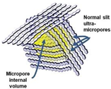
During the organic-to-inorganic ceramic transformation, the microstructure of polymeric precursors undergoes dramatic changes with increasing pyrolysis temperature [32][55]. As shown in Figure 67, the microporous properties and pore structure parameters (BET and micropore volume) of the pyrolytic precursor (polytitanocarbosilane, TiPCS) powders were analyzed by N2 adsorption–desorption isotherms [32][55]. The adsorption capacity, micropore volume, and BET surface area increased by firing from 500 °C to 650 °C and then decreased with increasing pyrolysis temperature from 650 °C to 1000 °C. It is worth noting that this is a general conclusion because PCS [55][57][72,96], polydimethylsilane (PMS) [58][97], and AHPCS [52][73] precursors follow the same trends within a similar pyrolysis temperature range of 300–850 °C. These trends suggest that the decomposition of organic groups generates many micropores at moderate temperatures and the micropores are then narrowed gradually as the pyrolysis temperature increases because of densification and rearrangement reactions.

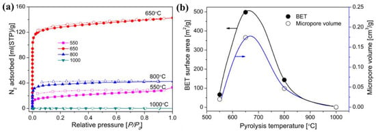
Figure 68. (a) N2 adsorption–desorption isotherms at 77 K, (b) BET surface area and micropore volume (at a relative pressure of P/P0 = 0.01, pore size ≤ 1 nm) of pyrolyzed precursor (TiPCS) powders. Adapted from [32][55] with permission from Elsevier.

The evolution of the network structure in polymeric precursors pyrolyzed at various temperatures is schematically illustrated in Figure 78. The evolution of the network structure starts with a dense polymer structure that passes through a loose transitional structure and is then transformed into a relatively denser ceramic structure [32][47][52][55][55,71,72,73]. It should be noted that this trend would ultimately affect the gas separation performance of membranes.
Figure 78. Schematic of the evolution of the network structure for polymeric precursors (e.g., AHPCS) pyrolyzed at different temperatures. Reprinted from [52][73] with permission from Elsevier.
ScholarVision Creations