Your browser does not fully support modern features. Please upgrade for a smoother experience.
Submitted Successfully!
 +1 credit
Thank you for your contribution! You can also upload a video entry or images related to this topic.
For video creation, please contact our Academic Video Service.
| Version | Summary | Created by | Modification | Content Size | Created at | Operation |
|---|---|---|---|---|---|---|
| 1 | Matiullah Ahsan | -- | 3534 | 2022-11-17 10:59:33 | | | |
| 2 | Beatrix Zheng | + 2 word(s) | 3536 | 2022-11-18 03:08:43 | | |
Video Upload Options
We provide professional Academic Video Service to translate complex research into visually appealing presentations. Would you like to try it?
Cite
If you have any further questions, please contact Encyclopedia Editorial Office.
Ahsan, M.; Baharom, M.N.R.B.; Zainal, Z.; Mahmod, L.H.; Ullah, I.; Yousof, M.F.M.; Jamail, N.A.M.; Kamarudin, M.S.; Rahman, R.A. Insulated Cross-Arm Technology. Encyclopedia. Available online: https://encyclopedia.pub/entry/35099 (accessed on 15 July 2026).
Ahsan M, Baharom MNRB, Zainal Z, Mahmod LH, Ullah I, Yousof MFM, et al. Insulated Cross-Arm Technology. Encyclopedia. Available at: https://encyclopedia.pub/entry/35099. Accessed July 15, 2026.
Ahsan, Matiullah, Md Nor Ramdon Bin Baharom, Zainab Zainal, Luqman Hakim Mahmod, Irshad Ullah, Mohd Fairouz Mohd Yousof, Nor Akmal Mohd Jamail, Muhammad Saufi Kamarudin, Rahisham Abd Rahman. "Insulated Cross-Arm Technology" Encyclopedia, https://encyclopedia.pub/entry/35099 (accessed July 15, 2026).
Ahsan, M., Baharom, M.N.R.B., Zainal, Z., Mahmod, L.H., Ullah, I., Yousof, M.F.M., Jamail, N.A.M., Kamarudin, M.S., & Rahman, R.A. (2022, November 17). Insulated Cross-Arm Technology. In Encyclopedia. https://encyclopedia.pub/entry/35099
Ahsan, Matiullah, et al. "Insulated Cross-Arm Technology." Encyclopedia. Web. 17 November, 2022.
Copy Citation
High-voltage transmission technology has advanced quickly with the overall development and increased use of renewable energy. More demands on the insulating system are made when high-voltage power systems evolve. One of the significant factors is the sharp rise in population density, which led to the high demand for electricity. Right-of-way infringement is a problem that frequently occurs these days. Transmission is done over a rated capacity; as a result, the transmission line heats up, the insulation ages, and the electric field becomes distorted. The insulating system is prone to fail too soon when the operating voltage inverses or when there is a significant temperature differential.
transmission lines
cross-arm
composite
1. Introduction
Electric power transmission is the bulk movement of energy from a generating site to an electrical substation. The interconnected lines that facilitate this movement are known as transmission networks. Efficient long-distance electric power transmission requires high voltages, which reduce the losses produced by heavy currents.
The steel tower has been used for high-voltage transmission lines for about 50 years [1]. The steel towers in Malaysia are of the type in the UK. This aging grid infrastructure requires increased power capacity to cope with increasing load demand. Infringement of high-voltage lines in populated areas, overheating of the conductor due to overrating, limitations of mechanical withstand capacity, and several other limitations result in the modification of cross-arm technology from time to time. This research presents a detailed analysis of advancements in cross-arm technology [2].
2. Insulated Cross-Arm Technology
Most transmission line towers have steel cross-arms with steel lattice towers. Although rust will always be a problem, the primary cause of ending the life of a steel cross-arm is reconducting with heavy conductors due to capacitance issues [3]. Support tie-bars are likely to fail in cross-arms because of their flexibility and low construction [4][5].
Reconductoring with a heavier conductor due to capacity issues is the primary cause of a steel cross-arm failing before its expected lifespan. In addition, because the support tie-bars are flexible and not as strong as the cross-arm, they are more likely to break before the cross-arm [5]. Conductor failures are not usual on average, 2000 conductors can fail in the UK each year through storms or corrosion. The primary causes of HD copper conductor failure are typical overloads caused by snow/ice, tree problems, and collisions (causing arcing) in high winds.
Insulator cross-arms are replaced by insulator strings and steel lattice cross-arms, which are mechanically strong enough to withstand the compression and tension forces. It has advantages such as allowing the voltage to be operated without compromising the necessary clearance to the tower and ground. Moreover, there is no swing angle because the insulator is an insulator [6].
Installing insulated cross-arms on an EHV transmission based on this concept began early in the mid-1960s. Kimoto et al. (1971) [7] successfully developed and tested a prototype insulator cross-arm for a 345 kV EHV transmission line. They proposed two design configurations, the first having four solid-core porcelain post-insulator columns of the quadruple type and the other using two solid-core columns and two-disc insulator strings (twin-arm type). Figure 1 shows an example of the quadrant type and twin-arm type. With these designs, no extra insulators are needed because the conductors are fitted directly to the end of the bridge.
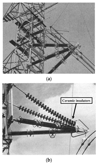
Figure 1. (a) Quadruple-type and (b) twin-arm ceramic insulator [7].
In 1998, Barbarito et al. published their work [8]. One year later, his group was involved in a work published by Cecchetti and Noferi [9]. These two papers discuss the idea of the use of insulators as cross-arms, using either regular insulator strings or solid-core porcelain insulators to be fitted on a new bi-dimensional steel tower structure. These configurations made the whole tower structure physically compact [10]. The new 400 kV tower design is calculated to reduce the right-of-way and tower/foundation costs by up to 10%. However, an increase of up to 5% is seen in the price of insulator fittings. A double-circuit 132 kV compact line was successfully built in 1987 in Italy.
In 1998, a similar concept was implemented near Lausanne in Switzerland by Energy Ouest Suisse. The new compact tower design was bi-dimensional with two legs, as shown in Figure 2. It was the first paper to explain in detail the use of hollow-core silicone rubber composite insulators as insulated cross-arms.

Figure 2. Comparison between compact lines and new lines for 400 kV [8].
Similar technology introduced by, Barbarito et al [11] is currently being applied by the utility company Tenga National Behard (TNB) Malaysia and has been for several years. The transmission lines are erected using the full composite tower type, as shown in Figure 3. However, this technology could only be utilised in the newly developed areas that enable new lines to be built but not on the existing lines within the developing township area. It can be seen that the technology applied to the power transmission lines erected along major routes in newly developed regions such as Cyberjaya, Selangor (Figure 3), Bandar Iskandar, Johor, and the DUKE highway in Kuala Lumpur. This technology is applied to the newly erected transmission lines in Cyberjaya. Although this technology enables only a small land area of occupation for the right-of-way route, it requires the complete removal of old tower structures on the existing lines (which is not viable for economic reasons). A solution for maintaining optimal current and voltage uprating the insulated cross-arms has potential benefits, such as allowing voltage uprating without compromising the needed clearances to the tower and ground. There is no swing angle because the cross-arm is an insulator [12]. Using novel technologies can achieve better mechanical and electrical performance at average operating temperatures.
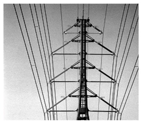
Figure 3. Front view of the compact tower [11].
In 2000, Cheong published work on the Chengal wooden cross-arm [13], which discusses the idea of the Chengal wooden cross-arm because Chengal cross-arms can withstand the weight of power cables and insulators. Also discussed are the drawbacks of wooden cross-arms. The disadvantages of wooden cross-arms are that attacks by fungi, termites, lightning strikes, and woodpeckers increase decomposition and ageing. The decay stages are categorised first by the amount of moisture the wood can absorb and second by the density of the wood at various decay stages at specific moisture content. Wood was categorised into severely decayed, incipiently decayed, sound categories, and interior deterioration or defective areas extending up to 2 cm from the wood’s surface. Figure 4 shows the failure of the wooden cross-arm due to the lighting cross-arm [14]. A higher amount of leakage current flows through a wet wood sample than a dry wood sample. Moisture content lowers the other wooden structures’ electrical resistivity and the risk of leakage currents [15]. The ability of decayed wood to absorb more water than the condition or quality of the wood cross-arm [16].
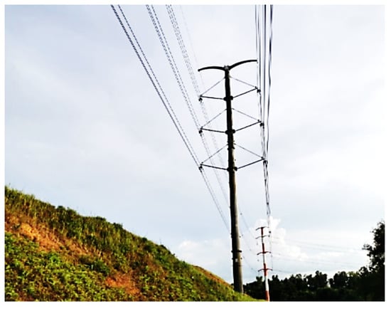
Figure 4. An example of TNB’s compact composite tower line erected in Cyberjaya Selangor [12].
In 2008, Grzybowski discussed the concept of a fibre cross-arm in place of the wooden cross-arm to investigate the electrical performance of the fibreglass cross in transmission lines based on AC voltage and current flash over voltage under dry and wet conditions [17][18]. There have been different tests on different lengths of fibre cross-arms. The benefits as compared with wooden cross-arms are listed below. Figure 5 shows a steel tower with a fibre cross-arm.
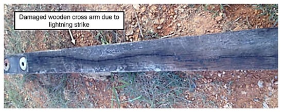
Figure 5. Failure of the wooden cross-arm due to lighting [14].
-
When all factors, particularly electrical performance, are considered, fibreglass cross-arms may be utilised instead of conventional cross-arms.
-
Fibreglass cross-arms cannot be the only insulation. It must be used as secondary insulation, with an insulator as the primary insulation.
-
For fibreglass cross-arms with porcelain insulators, the CFO voltage in dry and wet conditions is not significantly different. However, the AC flashover voltage in wet conditions is 50–60% lower than in dry conditions.
-
The CFO voltages of fibreglass cross-arms are 30–40% higher than wood in dry conditions and 40–50% higher in wet conditions.
-
The lightning impulse, wet flashover, wet withstand, and pollution withstand voltages of the FRP composite cross-arm increased by about 50%, 39.9%, 117%, and 30% compared with the iron cross-arm, respectively [19].
In 2009, Deng et al. published a paper on insulated cross-arms and towers made of composite material [20]. As a result, lightning protection and anti-pollution flashover for transmission lines have been improved; the transmission corridor width has been reduced; and land resources and total operation and maintenance costs have been saved. Compared with standard metal towers, composite material towers have unique advantages [21]. However, the present material does have some weak points or defects, such as large deflection, inadequate resistance to electrical erosion and electric arc, and weak hydrophobicity. The length of the cross-arm of fibreglass and wood increases, and the CFO voltage per unit length decreases [22]. This research reports that a 110 kV tower made of composite material was successfully built for the first time in China in 2009. Figure 6 shows a 110 kV tower of combined single-pole double-circuit material and a complete composite double-pole double-circuit material. The voltage of the power protection section changes from 10% to 50% under clear conditions to icy conditions because of the ice-covered insulator surface [23].
Figure 6. Fibre cross-arms on steel tower [18].
In 2010, Rowland et al. invented a new insulated cross-patent under PCT [24]. The inventors realized that an insulated cross-arm could replace the convention tower’s conductive cross-arm. The design of the new insulated cross-arm is shown in Figure 7 below.
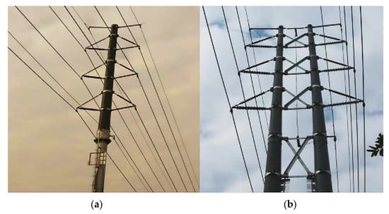
Figure 7. (a) 110 kV tower of combined composite single-pole double-circuit material and (b) 110 kV tower of complete composite double-pole double-circuit material [20].
-
The benefits of the cross-arms are below:
-
Resistance against buckling.
-
Lightweight.
-
Eliminate conductor swing toward the tower.
-
Used for high-voltage networks.
-
In 2010, Rowland et al. published work on increasing power capacity [25]. Using composite cross-arms with the new conductor overhead line tower shows a clear improvement in power capacity. The result of this paper is from a 275 kV tower in the UK.
The benefits of the composite cross arm are:
-
It allows voltage uprating to 400 kV without violating tower and ground clearances.
-
It allows the use of high-temperature HTLS conductors.
-
This structure’s advantage is that there is no swing angle.
-
Figure 8 shows the minimum clearance at 0°.
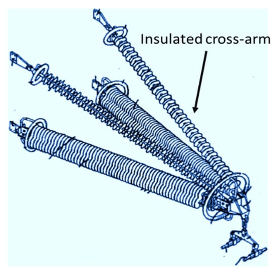
Figure 8. Insulated cross-patent under PCT [24].
In 2012, Selvaraj et al. published work on FRP pultruded profiles made of composite cross-arms [26][27]. In this case, FRP pultruded profiles are used [28]. The mechanical performance of the composite cross-arm was evaluated using experimental testing, an analytical solution, and a finite element simulation. A mechanical test on a composite cross-arm under simultaneous loads, applied in three perpendicular directions, is carried out, and the maximum deflection at the tip of the cross-arm is measured. The finite element model is developed to plot the leading stressed areas in good correlation, i.e., the error percentage is about 9–11% between theoretical and experimental results. A considerable reduction in transmission corridor is achieved by using the composite cross-arm in place of a steel cross-arm with ceramic insulators [29]. The systematics of the test setup and its photograph are shown in Figure 9.
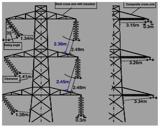
Figure 9. Clearances of 275 kV L3-type tower with regular suspension and modified composite cross-arm [25].
In 2012, Peesapati et al. published their work [30]. In these papers, composite insulators were replaced on the existing high-voltage insulator and the cross-arm of the transmission line tower. The analysis of the composite cross-arm justified it as an alternative solution. Moreover, the study is based on the scene when the composite arm is polluted or wet, which puts it under electrical stress [31]. Therefore, it is key to validating the design parameters widely accepted by electrical utilities. Figure 10 shows the full-scale model of the composite cross-arm.

Figure 10. (a) The systematics of the test setup and (b) photograph of the composite cross-arm under mechanical testing [26].
In 2013, Zachariades published their work on the behaviour of the cross-arm [32]. In this case, the electrical behaviour of the cross-arm is observed by monitoring the leakage current in real time. Due to the large cross-section area, the base leakage current profile of compression of the cross-arm is higher, and its response to changes in the weather is milder, with slight fluctuations. Extra work is being conducted to separate the effects of capacitive coupling and isolate the part of the leakage current caused by resistance. This research also reports that the two insulating cross-arms of 231 kV were successfully installed near the coast of Scotland [33]. The two insulating cross-arms of 231 kV on each side are on the west and the other on the south, as shown in Figure 11.
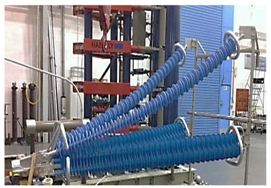
Figure 11. Full-scale prototype cross-arm [30].
In 2014, Yang et al. published a similar work on 750 kV [34]. In this work, they obtained the computational results of the potential and electric field distribution for composite cross-arms [35] in structural optimisation. The final design is made to omit the suspension insulator string, increase the length of post insulators, and configure proper grading and shielding rings. This research discusses the first composite cross-arm successfully installed on a 750 kV AC transmission line tower in China, shown in Figure 12 [36].
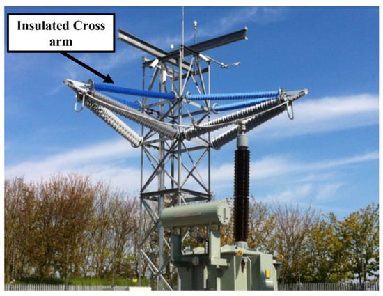
Figure 12. Two insulating cross-arms of 231 kV [32].
In 2015, Wang et al. published work on a 750 kV cross-arm [37]. The electric field distribution is calculated at the ultrahigh voltage of a 750 kV cross-arm with a silicone rubber sheath under light impulse voltage [38]. Each composite cross-arm insulator has similar voltages. As a result, fittings have similar electric field distributions. The maximum electric field strength difference is 0.6% to 2.9%. The impulse voltage tests [39] of the composite cross-arms are shown in Figure 13.
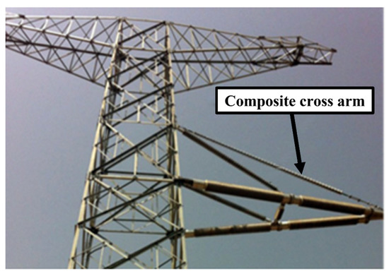
Figure 13. Picture of 750 kV composite cross-arms [34].
In 2017, Zhang et al. published work on a compact type of composite cross in tower design [40]. They analysed the cross-arm’s structural composition and connection mode by tightening the vibration and tower head structures of the cup tower, cathead tower, and upper-shape tower using composite cross-arms and made technical and economic comparisons among the three towers. As a result, the width of the corridor in the cup tower, the upper-shape tower, and the cathead tower were reduced by 3.2 m, 3 m, and 3.6 m, respectively. It solved the problem of making the corridor wider when the conventional tower was used. Technical and economic comparisons show that the width of the corridors in the three types of towers is reduced by 5.9 m, 5.8 m, and 3.2 m, respectively, and that the cost ratio is 116%, 120%, and 101%, respectively, compared with the cost ratio in conventional cup towers. After looking at everything, it was decided that the compact-type [41][42] cup tower with a composite cross-arm was the best in terms of technology and cost. The results of this research are taken from the Grid Henan Economic Research Institute in Henan, China.
In 2017, Bozkurt et al. published a paper on the economic analysis of transmission line towers [43]. As a result, right of way (ROW) decreases in 400 kV power transmission line towers using composite cross-arm insulators (four pultruded structure components) instead of pin-type and long-rod insulators, as shown in Figure 14. Moreover, insulator costs are reduced by using composite cross-arm insulators [44] instead of glass and porcelain pin-type insulators. In addition, as the span between towers increases, using composite cross-arm insulators instead of long-rod insulators is more economical. It saves energy during the time they are used.

Figure 14. Impulse voltage test for electric field computation [37].
In 2018, Syamsir et al. published a paper on the mechanical strength of fibre-reinforced polymers [45]. In this work, composites as an alternative to cross-arm structures are replaced by conventional cross-arms due to their simple production, light weight, mouldability, high-quality surface finishes, and superior mechanical qualities [46]. Creep is essential for an element’s maximum load-bearing capacity. Extreme creep deformation may damage or collapse a structure. After 6 and 14 months, GFRP creep lowered young’s modulus by 20%. The creep behaviour of the GFRP pultruded flexural component shows shear stiffness after 50 years with a 22% to 43% due to shear deformation instead of bending counterpart. Creep research on GFRP girders [47] shows an increase in immediate deflection of up to 40% after five months, demonstrating GFRP’s promise in structural sectors. The results of this research were taken from a 115 kV transmission line tower under the TNB transmission line division in Malaysia.
In 2019, Zhongguo et al. published a paper on a full-scale three-dimensional simulation model of an AC 500 kV transposition tower [48][49]. In 2015, certain composite insulators from Dongguan Power Supply Bureau’s 500 kV transposition towers were punctured, as shown in Figure 15. The electric field distribution was computed with the finite element method. As a result, the electric field in the transposition tower is more severely distorted, and the composite insulators are vulnerable. The electric field intensity on both ends of the same insulator is higher than that in the middle; that is to say, the distribution of electric fields is non-uniform along the composite insulator. The high-voltage end housing has the highest surface electric field intensity. The non-uniform electric field distributions on the surface of the insulator are caused by their different configurations of conductors, which is also why electric field distributions are different between transposition and regular towers. Changing the grading ring design or installing disc suspension porcelain insulators on the composite insulator’s high-voltage end helps balance the insulator’s electric field distribution on the transposition tower. The results of this research were taken from a report on a double-circuit 500 kV AC transmission line tower in China.
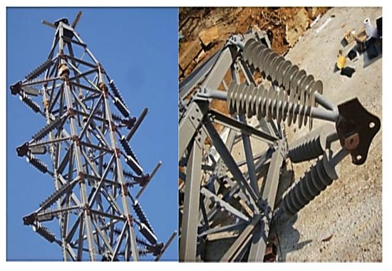
Figure 15. Composite cross-arm insulators (four pultruded structure components) [43].
In 2020, Asyraf et al. published work on green composite technology [48]. The cross-arm components are made from natural fibre with a reinforced biopolymer composite. It is a green composite material. Many researchers and industries are paying attention to this due to its excellent mechanical ability and the material’s green technology. Given that green composite cross- arms are novel in this area, some features, including creep, fatigue, and quasistatic mechanical performance, need to be found and assessed. It is thus essential to research more advanced processing procedures for natural fibre-reinforced biopolymer composite cross-arms to replace the traditional cross-arms in transmission towers. The green composite has the potential to substitute for FRP, PGFRP, and the wooden cross-arm shown in Figure 16.

Figure 16. Punctured insulator [49].
In 2021, Bao et al. published a paper on the model of a quadruple-circuit 500 kV transmission line [50]. The simulation and calculation analysis of lightning were completed with a steel tower. The research shows that the tolerance lighting level of CMCA towers is superior to conventional steel towers. The lightning withstand level of single-circuit flashover is 45% higher than that of a steel tower, and the minimum shielding failure lightning withstand level is 47% higher than that of the steel tower. The quadruple-circuit 500 kV transmission line CMCA tower is shown in Figure 17. The CMCA tower is more impacted by the grounding resistance change than the steel tower. The electrical withstand levels of the CMCA tower and steel tower decreased by 41.7% and 32.6%, respectively, as the ground resistivity increased from 5 to 20 Ω.

Figure 17. Potential application of green composite in cross-arm beams [48].
In 2021, Amir, A. et al. published a review on composite cross-arms [51]. The honeycomb-filled structure will still be a hotspot in engineering applications. The general honeycomb-filled concept is preferred over tandem and embedded honeycombs due to its easy manufacturing and straightforward configuration [52][53]. In addition to that, the honeycomb-filled structure allows an increase in strength, energy absorption, flexural behaviour, load-carrying capacity, and creep response shown in Figure 18. However, previous research shows that sandwich panels and beams with honeycomb-filled structures outperform the hollow system depicted in Figure 19 [54]. There is still limited information on the performance of pultruded glass fibre-reinforced polymer composite cross-arm (PGFRPC) honeycomb-filled structures. Several studies are needed to be identified and evaluated, such as:
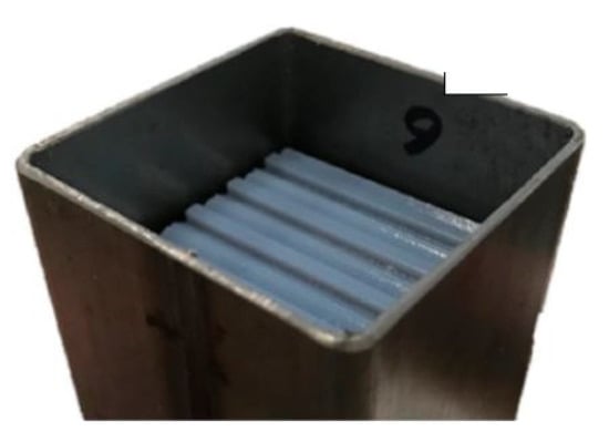
Figure 18. Honeycomb-filled structure [51].
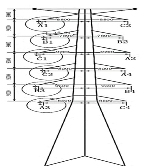
Figure 19. Structure of CMCA [50].
-
Improvement of the existing manufacturing process of composite structures to have an economical and highly efficient manufacturing method for honeycomb-filled PGFRPC cross-arm beams.
-
Furthermore, an actual-scale study of the honeycomb-filled PGFRPC cross-arm on related flexural characteristics, creep responses, load-carrying capacity, and failure mode behaviour.
-
They match honeycomb-core properties with PGFRPC beams due to deformation mode behaviour.
In 2021, Da Silva et al. published a paper on a Y-shaped tower [55]. A new Y-shaped composite pylon for a 2 × 400 kV overhead transmission line tower is proposed. Low-density polyethene material (LDPE) is used to fill in the cross-arm. In addition, the clamp structure was redesigned. The LPDE material prevents the electric field intensity in the cross-arm [56][57]. Furthermore, the conductor enclosure is removed, and the height of the clamp is reduced. A fully composite pylon without shield wires was the first alternative to using surge arresters to protect the pylon from electrical shocks [58].
-
The conductors are attached to the unibody cross-arm using special conductor clamps. The distance between phases on the pylon is the same as the arcing distances.
-
The two shield wires are fixed to the ends of the unibody cross-arm using clamps. As a result, the shielding angle is negative for the pylon.
-
The pylon requires a smaller transmission corridor than its counterparts. With a compact configuration, the pylon can fit more easily into the landscape and have less visual impact on the surrounding residents.
A Y-shaped composite pylon overhead line tower with a 30° tilt angle of the unibody cross-arm is shown in Figure 20, which indicates a unique visual form [59].
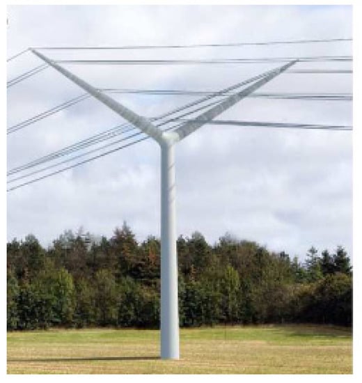
Figure 20. Y-shaped composite pylon overhead line tower [57].
In 2022, Asyraf et al. published a review on composite cross-arms [60]. In this paper, PGFRPC is replaced by a filament-wound polymer composite as the cross-arm structure in the lattice transmission tower. The materials used in filament winding are polyester resins [61]. The filament-wound composites improve stiffness, strength, and surface finish. The filament winding process makes it easy to install a cross-arm with a honeycomb-like core structure for better flexure properties and resistance to micro-cracking and flaking, shown in Figure 21.
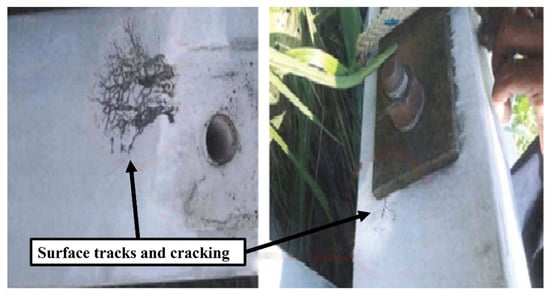
Figure 21. Surface tracking and cracks on the composite cross [60].
References
- Littler, D.J.; Davies, E.J.; Johnson, H.E. EHV Transmission, 3rd ed.; Elsevier: Amsterdam, The Netherlands, 1991; Volume K.
- Baharom, M. Composite Cross-Arms for Overhead Transmission. Ph.D. Thesis, School of Electrical Engineering, The University of Manchestor, Manchestor, UK, 2009.
- Rao, N.P.; Mohan, S.J.; Lakshmanan, N. A study on failure of cross arms in transmission line towers during prototype testing. Int. J. Struct. Stab. Dyn. 2005, 5, 435–455.
- Rao, N.P.; Knight, G.S.; Mohan, S.; Lakshmanan, N. Studies on failure of transmission line towers in testing. Eng. Struct. 2012, 35, 55–70.
- Papailiou, K. Composite insulators are gaining ground-25 years of Swiss experience. In Proceedings of the IEEE Power Engineering Society Transmission and Distribution Conference, New Orleans, LA, USA, 11–16 April 1999; Volume 2, pp. 827–833.
- I Performance: Combined Load Limitations of Composite Line Posts. 2022. Available online: https://www.inmr.com/combined-load-limitations-of-composite-line-posts (accessed on 18 March 2022).
- Kimoto, I.; Kito, K.; Ueno, K. Insulator Crossarms for 345-KV EHV Transmission Line. IEEE Trans. Power Appar. Syst. 1971, PAS-90, 756–767.
- Barbarito, M.; Clerici, A.; Paris, L.; Pelacchi, P. New type of compact line for urban and suburban areas. In Proceedings of the 1989 International Conference on Overhead Line Design and Construction: Theory and Practice, London, UK, 28–30 November 1988; Volume 297, pp. 40–45.
- Cecchett, E.; Noferi, P.L.; Barbarit, M.; Cleric, A.; Pelacch, P.; Sadelmi, S. Compact Lines for Urban Areas: A New Solution. Dev. Built Environ. 2016, 15, 1–23.
- Gençoğlu, M.T. The Comparison of Ceramic and Non-Ceramic Insulators. e-J. New World Sci. Acad. 2007, 2, 245.
- Burkhardt, B.; Baettig, G.; Terrasi, G.P.; Papailiou, K.O.; Schmuck, F. New Solutions With Composite Insulators And Composite Structures For Compact Lines. In Proceedings of the 17th International Conference on Electricity Distribution, Barcelona, Spain, 12–15 May 2003; pp. 12–15.
- Albizu, I.; Mazon, A.J.; Zamora, I. Methods for increasing the rating of overhead lines. In Proceedings of the IEEE Russia Power Tech, St. Petersburg, Russia, 27 January 2005; pp. 1–6.
- Khalid, K.; Hamami, M.; Cheong, N.K.; Fuad, S. Microwave reflection sensor for determination of decay in wooden cross-arms. In Proceedings of the IEEE International Conference on Properties and Applications of Dielectric Materials, Xi’an, China, 6 August 2002; pp. 595–598.
- Rawi, I.M.; Rahman, M.S.A.; Kadir, M.Z.A.A.; Izadi, M. Wood and fiberglass crossarm performance against lightning strikes on transmission towers. In Proceedings of the IPST—International Conference on Power Systems Transients, Seoul, Korea, 26–29 June 2017.
- Wong, K.L.; Pathak, S.; Yu, X.H. Leakage current flow through wooden pole structures of varying age on overhead distribution system. In Proceedings of the 2007 Australasian Universities Power Engineering Conference, Perth, WA, Australia, 9–12 December 2007; pp. 1–6.
- Khalida, K.; Sahrjb, M.H.; Keonga, N.K.; Fuadc, S.A. Microwave dielectric properties of wooden cross-arms. In Proceedings of the SPIE’s International Symposium on Optical Science, Engineering, and Instrumentation, Denver, CO, USA, 18–23 July 1999; Volume 3752.
- Grzybowski, S. Electrical performance of 115 kV transmission lines fiberglass crossarms aged in field. In Proceedings of the 5th International Conference on Properties and Applications of Dielectric Materials, Seoul, Korea, 25–30 May 1997; Volume 2, pp. 774–777.
- Klumb, F.R.; Chairman, G. 1986 IEEE/PES T&D Conference Update. In Proceedings of the Transmission and Distribution Conference and Exposition, Anaheim, CA, USA, 14–19 September 1986; Available online: https://ieeexplore.ieee.org/stamp/stamp.jsp?arnumber=5526542 (accessed on 10 October 2022).
- Dai, J.; Jia, Y.; Zhao, H.; Song, S.; Li, Z.; Wu, X. Investigation on the insulating properties of FRP composites cross arms for 10 kv distribution network. IET Conf. Publ. 2020, 2020, 1450–1453.
- Li, H.-M.; Deng, S.-C.; Wei, Q.-H.; Wu, Y.-N.; Xiang, Q.-Q. Research on composite material towers used in 110 kV overhead transmission lines. In Proceedings of the 2010 International Conference on High Voltage Engineering and Application, ICHVE, New Orleans, LA, USA, 11–14 October 2010; pp. 572–575.
- Chandrashekhara, K.; Watkins, S.E.; Nanni, A.; Kumar, P. Design and technologies for a smart composite bridge. In Proceedings of the 2004 IEEE Intelligent Transportation Systems Conference, Washington, DC, USA, 3–6 October 2004.
- An, L.; Yang, B. Structure Design and Analysis for 110 kV FRP Transmission Pole. In Proceedings of the International Con-ference on Logistics, Engineering, Management and Computer Science, Shenyang, China, 29–31 July 2015.
- Lu, J.; Zhao, C.; Jiang, Z.; Xie, P.; Hu, J. Simulation and experiment of a composite insulator with lightning protection and icing flashover prevention. In Proceedings of the 2014 International Conference on Lightning Protection, ICLP, Shanghai, China, 13–17 October 2014; pp. 1987–1991.
- Cotton, I.; Rowland, S.M.; Chambers, D.; Baharom, N.R.B.; Weatherby, N.; Thorne, M. Support Towers, Insulating Cross-Arms and Insulating Members for High Voltage Power Networks. Patent CA2771695C, 24 February 2011.
- Kopsidas, K.; Rowland, S.M.; Baharom, M.N.R.; Cotton, I. Power transfer capacity improvements of existing overhead line systems. In Proceedings of the 2010 IEEE International Symposium on Electrical Insulation, San Diego, CA, USA, 6–9 June 2010; pp. 1–5.
- Selvaraj, M.; Kulkarni, S.; Babu, R.R. Analysis and experimental testing of a built-up composite cross arm in a transmission line tower for mechanical performance. Compos. Struct. 2013, 96, 1–7.
- Izumi, K.; Takahashi, T.; Homma, H.; Kuroyagi, T. Development of line post type polymer insulation arm for 154 kV. IEEE Trans. Power Deliv. 2000, 15, 1304–1310.
- Wood, B.; Moore, T. Modifying Existing 138-kV Transmission Towers to 230-kV Capacity. In Proceedings of the 2005/2006 IEEE/PES Transmission and Distribution Conference and Exhibition, Dallas, TX, USA, 21–24 May 2006; pp. 1139–1143.
- Alipour, H.J.; Aminnejad, S.; Jazaeri, M. Decreasing the Right of Way of Transmission Lines by Using Towers with Polymer Insulation Arms. In Proceedings of the POWERENG 2007—International Conference on Power Engineering—Energy and Electrical Drives Proceedings, Setubal, Portugal, 12–14 April 2007; pp. 571–576.
- Peesapati, V.; Zachariades, C.; Li, Q.; Rowland, S.M.; Cotton, I.; Allison, F.; Chambers, D. 3D electric field computation of a composite cross-arm. In Proceedings of the Conference Record of IEEE International Symposium on Electrical Insulation, San Juan, PR, USA, 10–13 June 2012; pp. 464–468.
- Zachariades, C.; Cotton, I.; Rowland, S.M.; Peesapati, V.; Green, P.; Chambers, D.; Queen, M. A coastal trial facility for high voltage composite cross-arms. In Proceedings of the Conference Record of IEEE International Symposium on Electrical Insulation, San Juan, PR, USA, 10–13 June 2012; pp. 78–82.
- Zachariades, C.; Rowland, S.M.; Cotton, I. Real-time monitoring of leakage current on insulating cross-arms in relation to local weather conditions. In Proceedings of the 2013 IEEE Electrical Insulation Conference, EIC, Ottawa, ON, Canada, 2–5 June 2013; pp. 397–401.
- Zachariades, C.; Rowland, S.M.; Cotton, I.; Green, P.R.; Veerappan, C.A. A trial installation of high voltage composite cross-arms. In Proceedings of the 17th International Symposium on High Voltage Engineering, Hannover, Germany, 22–26 August 2011.
- Yang, X.; Li, N.; Peng, Z.; Liao, J.; Wang, Q. Potential distribution computation and structure optimization for composite cross-arms in 750 kV AC transmission line. IEEE Trans. Dielectr. Electr. Insul. 2014, 21, 1660–1669.
- Dumora, D.; Feldmann, D.; Gaudry, M. Mechanical behavior of flexurally stressed composite insulators. IEEE Trans. Power Deliv. 1990, 1999, 1660–1669.
- Shen, Z.; Yuze, L.; Bo, Z. Electric Fields Distribution of EHV AC Transmission Line Composite Insulators with Internal Conductive Defects. In Proceedings of the 2019 Asia Power and Energy Engineering Conference, APEEC, Macao, China, 1–4 December 2019; pp. 115–120.
- Yang, X.; Wang, Q.; Wang, H.; Zhang, S.; Peng, Z. Transient electric field computation for composite cross-arm in 750 kV AC transmission line under lightning impulse voltage. IEEE Trans. Dielectr. Electr. Insul. 2016, 23, 1942–1950.
- Lines, O.D. IEEE Standards. IEEE Spectr. 2012, 12, 98.
- Gao, Y.; Wang, E.; Li, Y.; Li, H. Analysis of transient electric field for epoxy spacer under lightning impulse voltage. IEEE Trans. Magn. 2006, 42, 595–598.
- Pei, H.; Zhang, Q.; Zhang, L.; Zhou, F.; Chen, C.; Niu, K. Application of Compact Type Composite Cross arm in Tower Design. In Proceedings of the 4th Annual International Conference on Material Engineering and Application (ICMEA 2017), Wuhan, China, 15–17 December 2018.
- Yao-Qin, L.; Feng, H.; Jing, N. Test and Simulation Analysis on the Electric Field Distribution Characteristics of UHVAC Composite Cross-arm Fittings. In Proceedings of the iSPEC 2019—2019 IEEE Sustainable Power and Energy Conference: Grid Modernization for Energy Revolution, Beijing, China, 21–23 November 2019; pp. 2905–2910.
- Hu, C.; Liu, T.; Liu, K.; Wu, T.; Xiao, B.; Peng, Y.; Su, Z.; Tang, P.; Le, X. Investigation on 110kV composite material pole: Effects of grounding methods on insulation of conductor-pole gaps. In Proceedings of the ICHVE 2016 IEEE International Conference on High Voltage Engineering and Application, Chengdu, China, 19–22 September 2016.
- Saudeger, K.; Bozkurt, A. Economic analysis of 400 KV transmission towers with cross arms in-sulators. Int. J. Acad. Res. Reflect. 2017, 5, 55–62.
- Rowland, S.M.; Maclaren, R.; Cotton, I.; Chambers, D.; Peesapati, V.; Zachariades, C. Development of insulating cross-arms for compact HV lattice tower structures. In Proceedings of the CIGRE Session 45–45th International Conference on Large High Voltage Electric Systems, Paris, France, 24–29 August 2014.
- Beddu, S.; Syamsir, A.; Ishak, Z.A.M.; Yusof, Z.M.; Hudi, N.S.; Nabihah, S. Creep behavior of glass fibre reinforced polymer structures in crossarms transmission line towers. In Proceedings of the AIP Conference Proceedings, Maharashtra, India, 5–6 July 2018; Volume 2031.
- Sanjay, M.R.; Yogesha, B. Studies on Natural/Glass Fiber Reinforced Polymer Hybrid Composites: An Evolution. Mater. Today Proc. 2017, 4, 2739–2747.
- Luís, J.; Martins, B. Quality and Durability Control of GFRP Structures Extended Abstract; Universidade Technica de Lisboa: Lisboa, Portugal, 2011.
- Asyraf, M.R.M.; Ishak, M.R.; Sapuan, S.M.; Yidris, N.; Ilyas, R.A.; Rafidah, M.; Razman, M.R. Potential Application of Green Composites for Cross Arm Component in Transmission Tower: A Brief Review. Int. J. Polym. Sci. 2020, 2020, 8878300.
- Guo, C.; Liu, L.; Yu, H.; Ma, Y.; Mei, H.; Wang, L. Electric Field Distribution Calculation and Analysis of Composite Insulators Operating on Double Circuit Transposition Tower in 500 kV Transmission Lines. In Proceedings of the 2nd International Conference on Electrical Materials and Power Equipment (ICEMPE), Guangzhou, China, 7–10 April 2019; pp. 486–489.
- Li, H.; Xiang, N.; Bao, H.; Jin, M.; Ding, L. Lightning protection performance of quadruple-circuit 500 kV transmission lines on the same tower with composite cross arm. Energy Rep. 2021, 8, 520–526.
- Amir, A.; Ishak, M.; Yidris, N.; Zuhri, M.; Asyraf, M. Potential of Honeycomb-Filled Composite Structure in Composite Cross-Arm Component: A Review on Recent Progress and Its Mechanical Properties. Polymers 2021, 13, 1341.
- Wang, Z.; Liu, J.; Lu, Z.; Hui, D. Mechanical behavior of composited structure filled with tandem honeycombs. Compos. Part B Eng. 2017, 114, 128–138.
- Wang, Z. Recent advances in novel metallic honeycomb structure. Compos. Part B Eng. 2019, 166, 731–741.
- Aktay, L.; Çakırolu, C.; Güden, M. Quasi-Static Axial Crushing Behavior of Honeycomb-Filled Thin-Walled Aluminum Tubes. Open Mat. Sci. J. 2011, 5, 184–193.
- Yin, K.; da Silva, F.F.; Bak, C.L.; Zhang, H.; Wang, Q.; Skouboe, H. Electric Field Computation and Optimization for A 400 kV Y-shaped Composite Cross-arm. In Proceedings of the ICEMPE 2021—3rd International Conference on Electrical Materials and Power Equipment, Chongqing, China, 11–15 April 2021; pp. 1–4.
- Jahangiri, T.; Wang, Q.; Bak, C.L.; da Silva, F.F.; Skouboe, H. Electric stress computations for designing a novel unibody composite cross-arm using finite element method. IEEE Trans. Dielectr. Electr. Insul. 2017, 24, 3567–3577.
- Anbarasan, R.; Usa, S. Electrical field computation of polymeric insulator using reduced dimension modeling. IEEE Trans. Dielectr. Electr. Insul. 2015, 22, 739–746.
- Jahangiri, T.; Wang, Q.; da Silva, F.F.; Bak, C.L. Overview of Composite-Based Transmission Pylons. In Lecture Notes in Electrical Engineering; Springer: Berlin, Germany, 2020; pp. 1–13.
- Wang, Q.; Bak, C.L.; da Silva, F.F.; Bystrup, E. A state of the art review-methods to evaluate electrical performance of composite cross-arms and composite-based pylons. In Proceedings of the 34th Electrical Insulation Conference, EIC, Montréal, QC, Canada, 19–22 June 2016; pp. 501–506.
- Asyraf, M.R.M.; Ishak, M.R.; Syamsir, A.; Amir, A.L.; Nurazzi, N.M.; Norrrahim, M.N.F.; Asrofi, M.; Rafidah, M.; Ilyas, R.A.; Rashid, M.Z.A.; et al. Filament-wound glass-fibre reinforced polymer composites: Potential applications for cross arm structure in transmission towers. Polym. Bull. 2022, 0123456789.
- Khennane, A. Filament winding processes in the manufacture of advanced fibre-reinforced polymer (FRP) composites. In Advanced Fibre-Reinforced Polymer (FRP) Composites for Structural Applications; Elsevier: Amsterdam, The Netherlands, 2013; pp. 187–206.
More
Information
Subjects:
Engineering, Electrical & Electronic
Contributors
MDPI registered users' name will be linked to their SciProfiles pages. To register with us, please refer to https://encyclopedia.pub/register
:
View Times:
6.1K
Revisions:
2 times
(View History)
Update Date:
18 Nov 2022
Table of Contents


Notice
You are not a member of the advisory board for this topic. If you want to update advisory board member profile, please contact office@encyclopedia.pub.
OK
Confirm
Only members of the Encyclopedia advisory board for this topic are allowed to note entries. Would you like to become an advisory board member of the Encyclopedia?
Yes
No
${ textCharacter }/${ maxCharacter }
Submit
Cancel
Back
Comments
${ item }
|
${ item.createdUser.fullName }
${ item.createdAt }
${ item.vote }
${ item.reply }
Delete
${ reply.createdUser.fullName }
${ reply.createdAt }
${ reply.vote }
Delete
There is no reply to this comment~
${ item.replyTextCharacter }/${ item.replyMaxCharacter }
Submit
Cancel
More
No more~
There is no comment~
${ textCharacter }/${ maxCharacter }
Submit
Cancel
${ selectedItem.replyTextCharacter }/${ selectedItem.replyMaxCharacter }
Submit
Cancel
Confirm
Are you sure to Delete?
Yes
No