Your browser does not fully support modern features. Please upgrade for a smoother experience.
Please note this is a comparison between Version 1 by Matiullah Ahsan and Version 2 by Beatrix Zheng.
High-voltage transmission technology has advanced quickly with the overall development and increased use of renewable energy. More demands on the insulating system are made when high-voltage power systems evolve. One of the significant factors is the sharp rise in population density, which led to the high demand for electricity. Right-of-way infringement is a problem that frequently occurs these days. Transmission is done over a rated capacity; as a result, the transmission line heats up, the insulation ages, and the electric field becomes distorted. The insulating system is prone to fail too soon when the operating voltage inverses or when there is a significant temperature differential.
- transmission lines
- cross-arm
- composite
1. Introduction
Electric power transmission is the bulk movement of energy from a generating site to an electrical substation. The interconnected lines that facilitate this movement are known as transmission networks. Efficient long-distance electric power transmission requires high voltages, which reduce the losses produced by heavy currents.
The steel tower has been used for high-voltage transmission lines for about 50 years [1]. The steel towers in Malaysia are of the type in the UK. This aging grid infrastructure requires increased power capacity to cope with increasing load demand. Infringement of high-voltage lines in populated areas, overheating of the conductor due to overrating, limitations of mechanical withstand capacity, and several other limitations result in the modification of cross-arm technology from time to time. This researchticle presents a detailed analysisreview of advancements in cross-arm technology [2].
2. Insulated Cross-Arm Technology
Most transmission line towers have steel cross-arms with steel lattice towers. Although rust will always be a problem, the primary cause of ending the life of a steel cross-arm is reconducting with heavy conductors due to capacitance issues [3][16]. Support tie-bars are likely to fail in cross-arms because of their flexibility and low construction [4][5][17,18].
Reconductoring with a heavier conductor due to capacity issues is the primary cause of a steel cross-arm failing before its expected lifespan. In addition, because the support tie-bars are flexible and not as strong as the cross-arm, they are more likely to break before the cross-arm [5][18]. Conductor failures are not usual on average, 2000 conductors can fail in the UK each year through storms or corrosion. The primary causes of HD copper conductor failure are typical overloads caused by snow/ice, tree problems, and collisions (causing arcing) in high winds.
Insulator cross-arms are replaced by insulator strings and steel lattice cross-arms, which are mechanically strong enough to withstand the compression and tension forces. It has advantages such as allowing the voltage to be operated without compromising the necessary clearance to the tower and ground. Moreover, there is no swing angle because the insulator is an insulator [6][19].
Installing insulated cross-arms on an EHV transmission based on this concept began early in the mid-1960s. Kimoto et al. (1971) [7][20] successfully developed and tested a prototype insulator cross-arm for a 345 kV EHV transmission line. They proposed two design configurations, the first having four solid-core porcelain post-insulator columns of the quadruple type and the other using two solid-core columns and two-disc insulator strings (twin-arm type). Figure 13 shows an example of the quadrant type and twin-arm type. With these designs, no extra insulators are needed because the conductors are fitted directly to the end of the bridge.
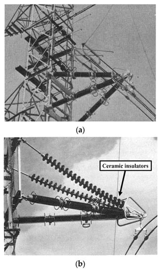
Figure 13.
(
a
) Quadruple-type and (
In 1998, Barbarito et al. published their work [8][21]. One year later, his group was involved in a work published by Cecchetti and Noferi [9][22]. These two papers discuss the idea of the use of insulators as cross-arms, using either regular insulator strings or solid-core porcelain insulators to be fitted on a new bi-dimensional steel tower structure. These configurations made the whole tower structure physically compact [10][23]. The new 400 kV tower design is calculated to reduce the right-of-way and tower/foundation costs by up to 10%. However, an increase of up to 5% is seen in the price of insulator fittings. A double-circuit 132 kV compact line was successfully built in 1987 in Italy.
In 1998, a similar concept was implemented near Lausanne in Switzerland by Energy Ouest Suisse. The new compact tower design was bi-dimensional with two legs, as shown in Figure 24. It was the first paper to explain in detail the use of hollow-core silicone rubber composite insulators as insulated cross-arms.

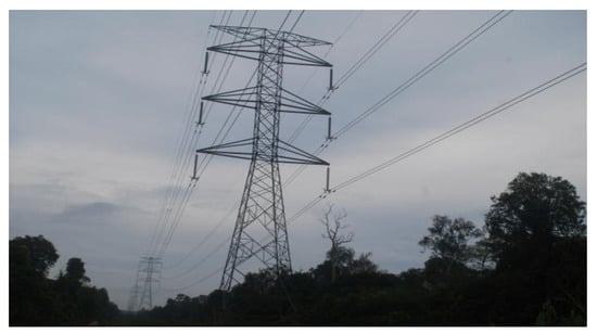
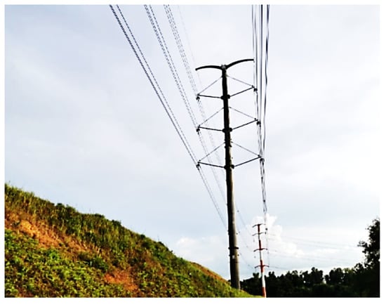
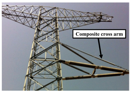
Similar technology introduced by, Barbarito et al [11][24] is currently being applied by the utility company Tenga National Behard (TNB) Malaysia and has been for several years. The transmission lines are erected using the full composite tower type, as shown in Figure 35. However, this technology could only be utilised in the newly developed areas that enable new lines to be built but not on the existing lines within the developing township area. ItWe can be seen that thsee the technology applied to the power transmission lines erected along major routes in newly developed regions such as Cyberjaya, Selangor (Figure 35), Bandar Iskandar, Johor, and the DUKE highway in Kuala Lumpur. This technology is applied to the newly erected transmission lines in Cyberjaya. Although this technology enables only a small land area of occupation for the right-of-way route, it requires the complete removal of old tower structures on the existing lines (which is not viable for economic reasons). A solution for maintaining optimal current and voltage uprating the insulated cross-arms has potential benefits, such as allowing voltage uprating without compromising the needed clearances to the tower and ground. There is no swing angle because the cross-arm is an insulator [12][25]. Using novel technologies can achieve better mechanical and electrical performance at average operating temperatures.
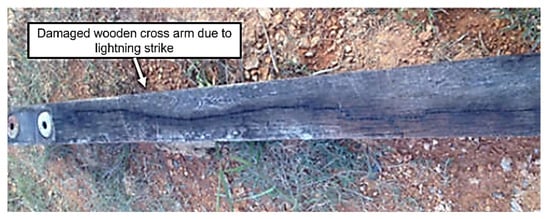
In 2000, Cheong published work on the Chengal wooden cross-arm [13][26], which discusses the idea of the Chengal wooden cross-arm because Chengal cross-arms can withstand the weight of power cables and insulators. Also discussed are the drawbacks of wooden cross-arms. The disadvantages of wooden cross-arms are that attacks by fungi, termites, lightning strikes, and woodpeckers increase decomposition and ageing. The decay stages are categorised first by the amount of moisture the wood can absorb and second by the density of the wood at various decay stages at specific moisture content. Wood was categorised into severely decayed, incipiently decayed, sound categories, and interior deterioration or defective areas extending up to 2 cm from the wood’s surface. Figure 46 shows the failure of the wooden cross-arm due to the lighting cross-arm [14][27]. A higher amount of leakage current flows through a wet wood sample than a dry wood sample. Moisture content lowers the other wooden structures’ electrical resistivity and the risk of leakage currents [15][28]. The ability of decayed wood to absorb more water than the condition or quality of the wood cross-arm [16][29].
In 2008, Grzybowski discussed the concept of a fibre cross-arm in place of the wooden cross-arm to investigate the electrical performance of the fibreglass cross in transmission lines based on AC voltage and current flash over voltage under dry and wet conditions [17][18][30,49]. There have been different tests on different lengths of fibre cross-arms. The benefits as compared with wooden cross-arms are listed below. Figure 57 shows a steel tower with a fibre cross-arm.
-
When all factors, particularly electrical performance, are considered, fibreglass cross-arms may be utilised instead of conventional cross-arms.
-
Fibreglass cross-arms cannot be the only insulation. It must be used as secondary insulation, with an insulator as the primary insulation.
-
For fibreglass cross-arms with porcelain insulators, the CFO voltage in dry and wet conditions is not significantly different. However, the AC flashover voltage in wet conditions is 50–60% lower than in dry conditions.
-
The CFO voltages of fibreglass cross-arms are 30–40% higher than wood in dry conditions and 40–50% higher in wet conditions.
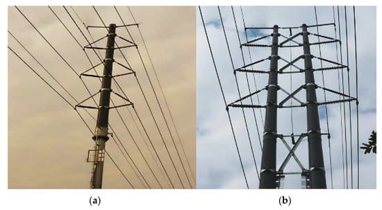
In 2009, Deng et al. published a paper on insulated cross-arms and towers made of composite material [20][31]. As a result, lightning protection and anti-pollution flashover for transmission lines have been improved; the transmission corridor width has been reduced; and land resources and total operation and maintenance costs have been saved. Compared with standard metal towers, composite material towers have unique advantages [21][32]. However, the present material does have some weak points or defects, such as large deflection, inadequate resistance to electrical erosion and electric arc, and weak hydrophobicity. The length of the cross-arm of fibreglass and wood increases, and the CFO voltage per unit length decreases [22][51]. This rpapesearchr reports that a 110 kV tower made of composite material was successfully built for the first time in China in 2009. Figure 68 shows a 110 kV tower of combined single-pole double-circuit material and a complete composite double-pole double-circuit material. The voltage of the power protection section changes from 10% to 50% under clear conditions to icy conditions because of the ice-covered insulator surface [23][52].
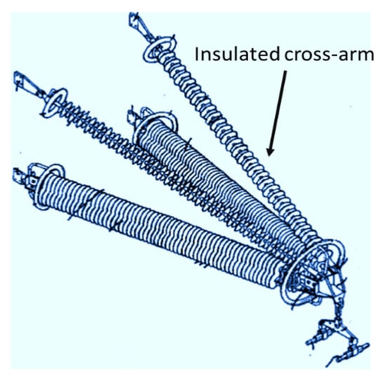
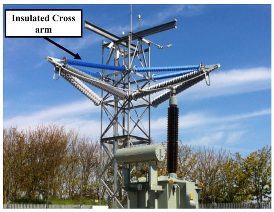
In 2010, Rowland et al. invented a new insulated cross-patent under PCT [24][53]. The inventors realized that an insulated cross-arm could replace the convention tower’s conductive cross-arm. The design of the new insulated cross-arm is shown in Figure 79 below.
[33]. Using composite cross-arms with the new conductor overhead line tower shows a clear improvement in power capacity. The result of this paper is from a 275 kV tower in the UK.
The benefits of the composite cross arm are:
-
It allows voltage uprating to 400 kV without violating tower and ground clearances.
-
It allows the use of high-temperature HTLS conductors.
-
This structure’s advantage is that there is no swing angle.
-
Figure 810 shows the minimum clearance at 0°.
-
The benefits of the cross-arms are below:
-
Resistance against buckling.
-
Lightweight.
-
Eliminate conductor swing toward the tower.
-
Used for high-voltage networks.
-
In 2012, Selvaraj et al. published work on FRP pultruded profiles made of composite cross-arms [26][27][34,54]. In this case, FRP pultruded profiles are used [28][55]. The mechanical performance of the composite cross-arm was evaluated using experimental testing, an analytical solution, and a finite element simulation. A mechanical test on a composite cross-arm under simultaneous loads, applied in three perpendicular directions, is carried out, and the maximum deflection at the tip of the cross-arm is measured. The finite element model is developed to plot the leading stressed areas in good correlation, i.e., the error percentage is about 9–11% between theoretical and experimental results. A considerable reduction in transmission corridor is achieved by using the composite cross-arm in place of a steel cross-arm with ceramic insulators [29][56]. The systematics of the test setup and its photograph are shown in Figure 911.
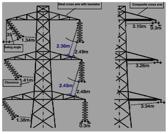
Figure 911. Clearances of 275 kV L3-type tower with regular suspension and modified composite cross-arm [25].
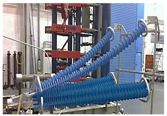
In 2012, Peesapati et al. published their work [30][35]. In these papers, composite insulators were replaced on the existing high-voltage insulator and the cross-arm of the transmission line tower. The analysis of the composite cross-arm justified it as an alternative solution. Moreover, the study is based on the scene when the composite arm is polluted or wet, which puts it under electrical stress [31][57]. Therefore, it is key to validating the design parameters widely accepted by electrical utilities. Figure 102 shows the full-scale model of the composite cross-arm.

Figure 102.
(
a
) The systematics of the test setup and (
In 2013, Zachariades published their work on the behaviour of the cross-arm [32][36]. In this case, the electrical behaviour of the cross-arm is observed by monitoring the leakage current in real time. Due to the large cross-section area, the base leakage current profile of compression of the cross-arm is higher, and its response to changes in the weather is milder, with slight fluctuations. Extra work is being conducted to separate the effects of capacitive coupling and isolate the part of the leakage current caused by resistance. This rpapesearchr also reports that the two insulating cross-arms of 231 kV were successfully installed near the coast of Scotland [33][58]. The two insulating cross-arms of 231 kV on each side are on the west and the other on the south, as shown in Figure 113.
In 2014, Yang et al. published a similar work on 750 kV [34][37]. In this work, they obtained the computational results of the potential and electric field distribution for composite cross-arms [35][59] in structural optimisation. The final design is made to omit the suspension insulator string, increase the length of post insulators, and configure proper grading and shielding rings. This rpapesearchr discusses the first composite cross-arm successfully installed on a 750 kV AC transmission line tower in China, shown in Figure 124 [36][60].
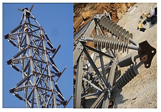
In 2015, Wang et al. published work on a 750 kV cross-arm [37][38]. The electric field distribution is calculated at the ultrahigh voltage of a 750 kV cross-arm with a silicone rubber sheath under light impulse voltage [38][61]. Each composite cross-arm insulator has similar voltages. As a result, fittings have similar electric field distributions. The maximum electric field strength difference is 0.6% to 2.9%. The impulse voltage tests [39][62] of the composite cross-arms are shown in Figure 135.
In 2017, Zhang et al. published work on a compact type of composite cross in tower design [40][39]. They analysed the cross-arm’s structural composition and connection mode by tightening the vibration and tower head structures of the cup tower, cathead tower, and upper-shape tower using composite cross-arms and made technical and economic comparisons among the three towers. As a result, the width of the corridor in the cup tower, the upper-shape tower, and the cathead tower were reduced by 3.2 m, 3 m, and 3.6 m, respectively. It solved the problem of making the corridor wider when the conventional tower was used. Technical and economic comparisons show that the width of the corridors in the three types of towers is reduced by 5.9 m, 5.8 m, and 3.2 m, respectively, and that the cost ratio is 116%, 120%, and 101%, respectively, compared with the cost ratio in conventional cup towers. After looking at everything, it was decided that the compact-type [41][42][63,64] cup tower with a composite cross-arm was the best in terms of technology and cost. The results of this rpapesearchr are taken from the Grid Henan Economic Research Institute in Henan, China.
In 2017, Bozkurt et al. published a paper on the economic analysis of transmission line towers [43][40]. As a result, right of way (ROW) decreases in 400 kV power transmission line towers using composite cross-arm insulators (four pultruded structure components) instead of pin-type and long-rod insulators, as shown in Figure 146. Moreover, insulator costs are reduced by using composite cross-arm insulators [44][65] instead of glass and porcelain pin-type insulators. In addition, as the span between towers increases, using composite cross-arm insulators instead of long-rod insulators is more economical. It saves energy during the time they are used.

In 2018, Syamsir et al. published a paper on the mechanical strength of fibre-reinforced polymers [45][41]. In this work, composites as an alternative to cross-arm structures are replaced by conventional cross-arms due to their simple production, light weight, mouldability, high-quality surface finishes, and superior mechanical qualities [46][42]. Creep is essential for an element’s maximum load-bearing capacity. Extreme creep deformation may damage or collapse a structure. After 6 and 14 months, GFRP creep lowered young’s modulus by 20%. The creep behaviour of the GFRP pultruded flexural component shows shear stiffness after 50 years with a 22% to 43% due to shear deformation instead of bending counterpart. Creep research on GFRP girders [47][66] shows an increase in immediate deflection of up to 40% after five months, demonstrating GFRP’s promise in structural sectors. The results of this rpapesearchr were taken from a 115 kV transmission line tower under the TNB transmission line division in Malaysia.
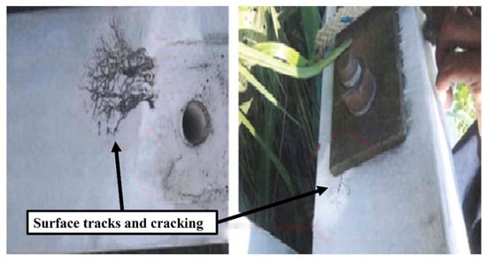
In 2019, Zhongguo et al. published a paper on a full-scale three-dimensional simulation model of an AC 500 kV transposition tower [48][49][43,67]. In 2015, certain composite insulators from Dongguan Power Supply Bureau’s 500 kV transposition towers were punctured, as shown in Figure 157. The electric field distribution was computed with the finite element method. As a result, the electric field in the transposition tower is more severely distorted, and the composite insulators are vulnerable. The electric field intensity on both ends of the same insulator is higher than that in the middle; that is to say, the distribution of electric fields is non-uniform along the composite insulator. The high-voltage end housing has the highest surface electric field intensity. The non-uniform electric field distributions on the surface of the insulator are caused by their different configurations of conductors, which is also why electric field distributions are different between transposition and regular towers. Changing the grading ring design or installing disc suspension porcelain insulators on the composite insulator’s high-voltage end helps balance the insulator’s electric field distribution on the transposition tower. The results of this rpapesearchr were taken from a report on a double-circuit 500 kV AC transmission line tower in China.
In 2020, Asyraf et al. published work on green composite technology [48][43]. The cross-arm components are made from natural fibre with a reinforced biopolymer composite. It is a green composite material. Many researchers and industries are paying attention to this due to its excellent mechanical ability and the material’s green technology. Given that green composite cross- arms are novel in this area, some features, including creep, fatigue, and quasistatic mechanical performance, need to be found and assessed. It is thus essential to research more advanced processing procedures for natural fibre-reinforced biopolymer composite cross-arms to replace the traditional cross-arms in transmission towers. The green composite has the potential to substitute for FRP, PGFRP, and the wooden cross-arm shown in Figure 168.
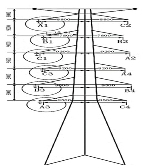
In 2021, Bao et al. published a paper on the model of a quadruple-circuit 500 kV transmission line [50][45]. The simulation and calculation analysis of lightning were completed with a steel tower. The research shows that the tolerance lighting level of CMCA towers is superior to conventional steel towers. The lightning withstand level of single-circuit flashover is 45% higher than that of a steel tower, and the minimum shielding failure lightning withstand level is 47% higher than that of the steel tower. The quadruple-circuit 500 kV transmission line CMCA tower is shown in Figure 179. The CMCA tower is more impacted by the grounding resistance change than the steel tower. The electrical withstand levels of the CMCA tower and steel tower decreased by 41.7% and 32.6%, respectively, as the ground resistivity increased from 5 to 20 Ω.

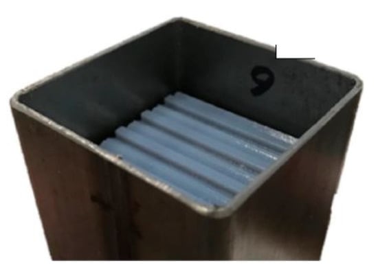
In 2021, Amir, A. et al. published a review on composite cross-arms [51][68]. The honeycomb-filled structure will still be a hotspot in engineering applications. The general honeycomb-filled concept is preferred over tandem and embedded honeycombs due to its easy manufacturing and straightforward configuration [52][53][44,69]. In addition to that, the honeycomb-filled structure allows an increase in strength, energy absorption, flexural behaviour, load-carrying capacity, and creep response shown in Figure 1820. However, previous research shows that sandwich panels and beams with honeycomb-filled structures outperform the hollow system depicted in Figure 219 [54][46]. There is still limited information on the performance of pultruded glass fibre-reinforced polymer composite cross-arm (PGFRPC) honeycomb-filled structures. Several studies are needed to be identified and evaluated, such as:
-
Improvement of the existing manufacturing process of composite structures to have an economical and highly efficient manufacturing method for honeycomb-filled PGFRPC cross-arm beams.
-
Furthermore, an actual-scale study of the honeycomb-filled PGFRPC cross-arm on related flexural characteristics, creep responses, load-carrying capacity, and failure mode behaviour.
-
They match honeycomb-core properties with PGFRPC beams due to deformation mode behaviour.
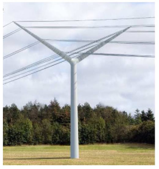
In 2021, Da Silva et al. published a paper on a Y-shaped tower [55][47]. A new Y-shaped composite pylon for a 2 × 400 kV overhead transmission line tower is proposed. Low-density polyethene material (LDPE) is used to fill in the cross-arm. In addition, the clamp structure was redesigned. The LPDE material prevents the electric field intensity in the cross-arm [56][57][70,71]. Furthermore, the conductor enclosure is removed, and the height of the clamp is reduced. A fully composite pylon without shield wires was the first alternative to using surge arresters to protect the pylon from electrical shocks [58][72].
-
The conductors are attached to the unibody cross-arm using special conductor clamps. The distance between phases on the pylon is the same as the arcing distances.
-
The two shield wires are fixed to the ends of the unibody cross-arm using clamps. As a result, the shielding angle is negative for the pylon.
-
The pylon requires a smaller transmission corridor than its counterparts. With a compact configuration, the pylon can fit more easily into the landscape and have less visual impact on the surrounding residents.
A Y-shaped composite pylon overhead line tower with a 30° tilt angle of the unibody cross-arm is shown in Figure 202, which indicates a unique visual form [59][73].
In 2022, Asyraf et al. published a review on composite cross-arms [60][48]. In this paper, PGFRPC is replaced by a filament-wound polymer composite as the cross-arm structure in the lattice transmission tower. The materials used in filament winding are polyester resins [61][74]. The filament-wound composites improve stiffness, strength, and surface finish. The filament winding process makes it easy to install a cross-arm with a honeycomb-like core structure for better flexure properties and resistance to micro-cracking and flaking, shown in Figure 213.

