Interaction of the ionizing radiation with the coolant (water) results in the generation of a variety of radiolysis products, with those being identified to include e−aq, H, OH, H2O2, HO2, HO2-, O2, O2-, O22-, O−, O, H2, OH−, H+ and possibly others. These species are electroactive (i.e., they can participate in charge transfer reactions at metal/solution interfaces), thereby impacting corrosion processes and may lead to enhanced damage and to failure of components in the reactor primary coolant circuits by generating an excessively high electrochemical corrosion potential (ECP). Therefore, to understand and predict the impact of corrosion on the structural materials in the IBED PHTS of the ITER, the concentrations of these species must be known. While methods are available for measuring the concentrations of some of the radiolysis products (e.g., O2, H2, H2O2) in the laboratory, few techniques are presently available for measuring the concentrations of the more energetic species, such as e−aq, OH, HO2, O−, O, O2-, O22- and O2−, all of which are present at very low concentrations, in a plant environment, although absorption spectroscopic methods are used with great success in the laboratory and might be adapted to the field. However, from an electrochemical/corrosion viewpoint, there is no pressing need for knowing the concentrations of many of these highly energetic species. This is because the contribution that any given species makes to determining the ECP and the corrosion rate is roughly proportional to its concentrations because the rate of transport to the surface and the partial current density are often mass transport controlled and hence are proportional to the concentration.
2. A Brief Primer on the Physics and Technology of ITER
One great advantage afforded by fusion as an energy source is demonstrated in Table 1, which summarizes the mass conversions for five different energy production technologies. The conversion values are calculated using Einstein’s energy/mass equivalence formula: ΔE=Δmc2, from the known energy yields, where ΔE is the energy produced upon conversion of a rest mass of Δm and c is the velocity of light (3 × 10⁸ m/s). One sees from these data that the nuclear technologies—fission of 235U92 and the fusion of deuterium and tritium—are by far the most efficient in converting mass into energy, except for particle/antiparticle annihilation (e.g., e−-p+), for which the conversion efficiency is 100%. However, a cost-effective method for producing antiparticles (positrons) in sufficient amounts has yet to be devised to render this reaction to be of practical interest. It is also noted that of the technologies identified in Table 1, all but fusion and particle/antiparticle annihilation are currently contributing electrical energy to the national grid.
Table 1. Mass conversion factors for various energy production technologies.
A second great advantage of fusion power is the limited amount of waste that is produced per unit of energy produced. Thus, according to an ORNL pamphlet, a small US city of 100,000 homes over 1 month requires 330,000,000 MJ of energy. If powered by coal, 150 railroad cars of bituminous coal are required that would produce 31,135 metric tons of CO2; 31 metric tons of CO; 67 metric tons of NOx; 365 tons of SOx; 411 metric tons of particulates; and 33 kg of formaldehyde, in addition to about 22 lbs (10 kg) of U and 57.6 lbs (26 kg) of Th. On the other hand, a fusion reactor would consume 5 kg of D (2H1) and T (3H1) and produce 4 kg of helium (4He2), for which a market already exists. Clearly, from an environmental impact viewpoint, fusion is the preferred technology. However, the production of high-energy neutrons necessarily means that neutron activation and transformation of some elements in the structural materials will occur. Accordingly, a radioactive disposal problem upon decommissioning will be faced, not unlike that in the decommissioning of a fission reactor.
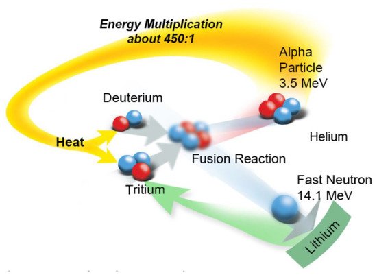
A schematic of the D–T fusion reaction, which has the lowest “ignition temperature” of alternative fission reactions listed in
Table 2, is presented in
Figure 1. It is seen that fusion is envisioned to occur via the fusion of the two nuclei to produce an unstable quasi-nucleus, comprising two protons and three neutrons. This entity then decomposes to produce a high-energy alpha particle (
4He
2, 3.5 MeV) and a high-energy neutron (
1n
0, 14.1 MeV) with a concomitant loss of mass, in addition to γ-photons of 15–25 MeV. For fusion to occur, the D and T nuclei must approach one another to within a few diameters of the nucleus (a few femtometers), where the strong nuclear force can overcome coulombic repulsion and quantum mechanical tunneling of nucleons from one nucleus to the other can occur. This can only occur at very high kinetic energies that are sufficiently high that positively charged nuclei can approach one another to the requisite distance for tunneling to occur; that requires very high temperatures, of the order of 20 keV or more than 300,000,000 K. The energy released during the fusion process theoretically represents a 450:1 multiplication over the energy required to heat hydrogen nuclei to the fusion point
[1].
Figure 1. Schematic of the D–T fusion reaction. ©2018 US ITER.
Attempts to harness fusion power have been underway since the 1950s, during which two basic approaches have evolved. The first, toroidal magnetic confinement fusion (MCF), is a Russian invention in which a low-density D–T plasma is confined magnetically in a toroidal chamber and is heated to fusion temperatures using extremely-high-density current and high-energy neutral particle and/or ion injection. In the second approach, inertial confinement fusion (ICF), or laser implosion, a mixture of D–T is contained within a small pellet, which is pulse irradiated from all sides using high-energy lasers, with the resulting adiabatic compression raising the temperature to the fusion threshold. Thus, these two fusion devices attempt to emulate the processes that power the sun and the stars—viz. the fusion of deuterium (2H1) and tritium (3H1): 2H1 + 3H1 → 4He2 (3.5 MeV) + 1n0 (14.1 MeV), as noted above, and that occur in thermonuclear weapons, respectively. However, several other fusion reactions involving the isotopes of hydrogen, as summarized in Table 2, are also possible. As noted above, the D–T reaction has the lowest “ignition temperature”, and hence this reaction is of the greatest interest in current fusion technology. It is also the reaction that results in the greatest conversion of mass into energy. Because this case uses tritium, which is not naturally occurring, tritium must be “bred” from some other nucleus, such as that described by the reaction 7Li3(1n0,4He2)3H1. On the other hand, if the D–D reaction was chosen, D is of plentiful supply in nature, as about 140 ppm of this isotope exists in natural water and the technology for its extraction is well developed. However, it requires a higher ignition temperature, and the mass conversion factor is not as attractive as the D–T reaction.
In 1957, Lawson
[2] derived the conditions that must be attained in the plasma for “breakeven” fusion (i.e., energy produced by fusion exceeding the energy input) as the “triple product”:
ITER is an example of the first approach (MCF) and is the logical extension of JET (Joint European Torus), which is operated in Oxford, England, UK. JET achieved a Q-value (i.e., the energy produced from fusion/input energy to heat the plasma) of 0.67 (16 MW out for 24 MW in), but ITER is expected to yield Q ≥ 10 (500 MW out for 50 MW in) over a sustained “burn” of about 550 s followed by a dwell period of 1250 s, to yield a repetition period of 1800 s (Table 3). Thus, ITER is a confined plasma device comprising a toroidal vacuum chamber and 5.3 T, Nb3Sn superconducting magnets that are designed to confine the hot plasma away from the walls.
Table 3. ITER Tokamak operating parameters (from ITER Technical Basis
[3]).
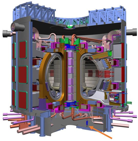
Figure 2 provides a schematic layout of ITER’s Tokamak building, with the scale being indicated at the bottom of the figure. The Tokamak, itself, is located within a reinforced concrete building. The effluent of greatest concern is tritium (
3H
1 →
3He
2+ +
0e
−1− +
v¯e,
t1/2 = 12.32 years,
E = 18.6 keV) because it readily diffuses through steel pipe walls. Accordingly, tritium must be removed by various scrubbing devices. Moreover,
16N
7 and
17N
7, which are produced by the nuclear reactions
16O
8(
1n
0,
1p
1)
16N
7 and
17O
8(
1n
0,
1p
1)
17N
7, respectively, are a potential radiological contamination issue. Both are radioactive (
16N
7 →
16O
8 + β + γ and
17N
7 → 17O
8 + β +
ν¯e) and will be produced in the radiation zone. They will then be carried by the coolant to non-irradiated regions of the PHTS, where they will establish γ fields that will contribute to the main REM cost of operation, like that of a BWR operating on Hydrogen Water Chemistry (HWC). One critically important engineering consideration is the need for great rigidity of the tokamak structure, particularly the coils because they are subjected to high Lorentz forces produced by the circulating plasma in the magnetic field. Any distortion of the structure could affect the shape and stability of the plasma. Additional details on the structure of the Tokamak and the reactor building and related matters are given in
[2][3][4][5][6][7][8][9][10][11][12][13][14][15][16][17][18][19][20][21][22][23][24][25][26][27][28][29][30][31].
Figure 2. Cutaway view of the ITER fusion reactor (from ITER Technical Basis
[3]). Note the size of the device in comparison with the human figure. ©2002 IAEA.
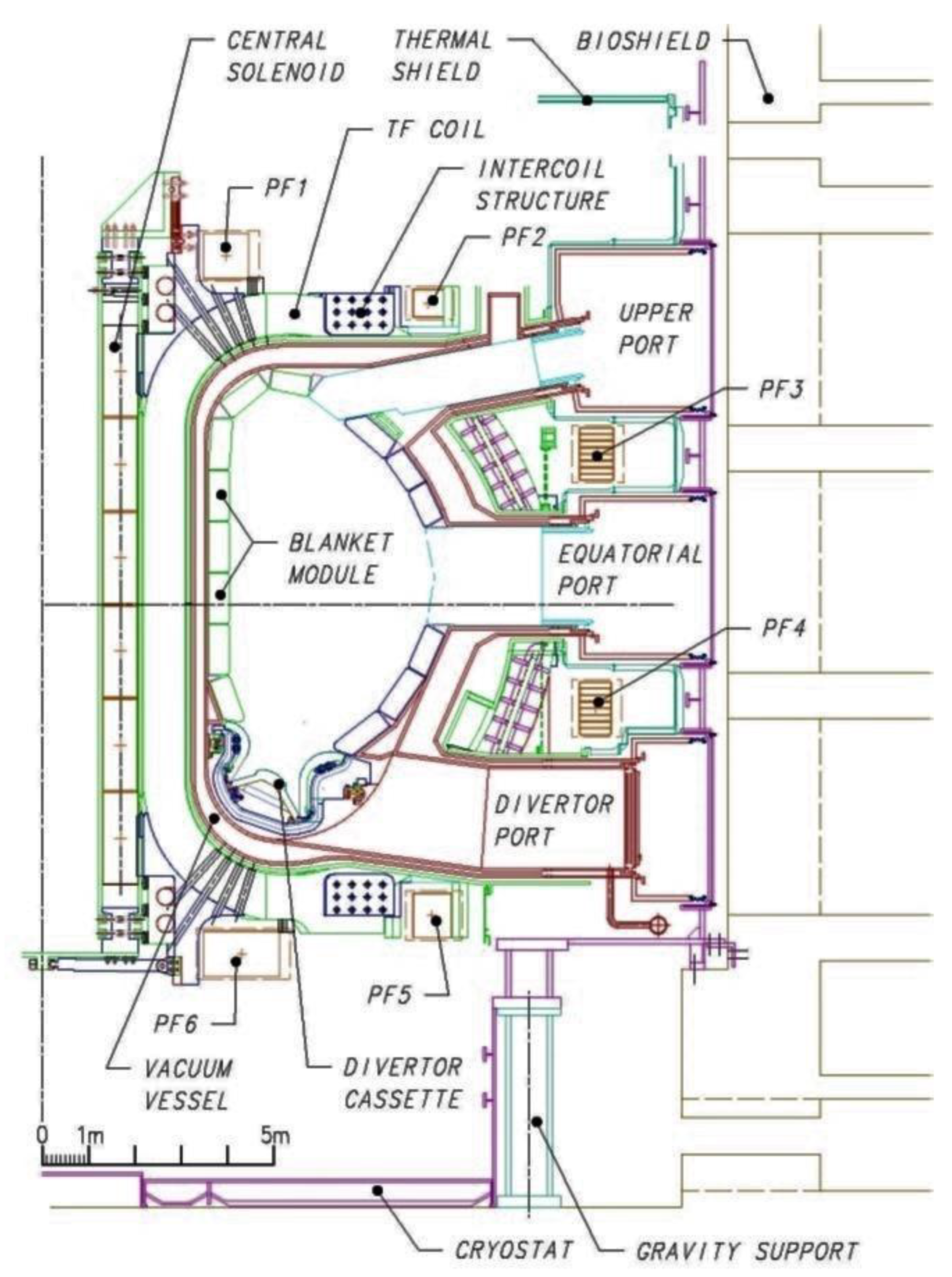
As noted above, the plasma is confined within the toroid by the magnetic field generated by the superconducting toroidal field (TF) coils and the central solenoid and is shaped by the six poloidal field (PF) coils (PF1 … PF6), which also protect the ports into the vacuum chamber, the blanket modules, the DIV cassette, and the control coils, as shown in Figure 3. The principal objective of this strong, shaped magnetic field is to keep the plasma away from the toroid walls. Since the plasma is at a temperature that corresponds well more than 300,000,000 K, no material, including beryllium, could withstand a “plasma strike”. Even if it did survive a transitory strike, the plasma would be contaminated that would interfere with the fusion process. Accordingly, the containment of the plasma is vitally important in magnetic confinement fusion technology.
Figure 3. Vertical cross section of the ITER Tokamak. TF = toroidal field; PF = poloidal field. The six poloidal field coils that are used to shape the plasma are depicted as PF1, PF2, …, PF6 (from ITER Technical Basis
[3]). ©2002 IAEA.
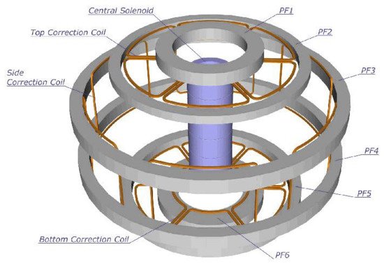
Figure 4 illustrates the spatial arrangement of the PF coils and error field correction coils in the ITER Tokamak. The error correction coils are used to correct for any imperfections in the magnetic field symmetry that is shaped by the TF and PF coils (Figure 3 and Figure 4).
Figure 4. Correction coil arrangement in the ITER Tokamak (PF coils and error field correction coils (from ITER Technical Basis
[3]). ©2002 IAEA.
Table 3 summarizes the operating conditions envisioned for ITER. These are various design parameters and actual conditions that will be ascertained upon operation. Because the minimal Q value (Q = 10) is required for the demonstration of fusion power viability, the Q-value is particularly important. Anything short of this goal would require a major redesign of ITER and possibly development of an entirely new machine.
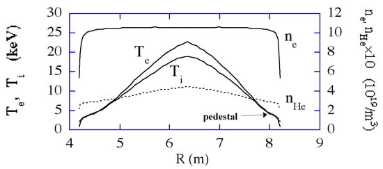
Figure 5 provides the electron temperature, ion temperature, electron density, and helium density, and Figure 6 depicts the configuration of the plasma. Most important is the need to ensure that the extremely hot plasma does not contact the walls of the cavity because no material can withstand contact with the plasma without vaporizing. Preventing this contact is primarily the role of the six poloidal field coils (Figure 3), which also ensure plasma stability. The toroidal vacuum vessel is double-walled stainless steel and lined with Be-armored blanket modules, whose function is, amongst others, to breed tritium via 6Li3 + 1n0 → 3H1 + 4He2 and to shield the vacuum vessel wall from errant instabilities of the plasma.
Figure 5. Profiles of electron temperature (
Te), ion temperature (
Ti), electron density (
ne), and helium density (
nHe) through the toroidal cavity (from ITER Technical Basis
[3]). ©2002 IAEA.
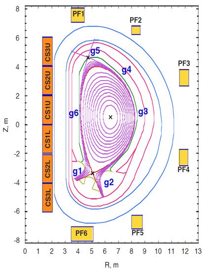
Figure 6. ITER nominal plasma configuration. The upper and lower “×” points are on different magnetic surfaces, defining two separatrixes, the primary one within the secondary one. The g1, g2, …, g6 refer to gaps whose sizes are control variables for plasma stability. The six poloidal field coils that are used to shape the plasma are depicted as PF1, PF2, …, PF6 (from ITER Technical Basis
[3]). ©2002 IAEA.
 +1 credit