 +1 credit
Video Upload Options
Batteries and hydrogen storage technologies are treated as complementary technologies in some cases, but in other ones they are considered opposed technologies.
1. Introduction
| Technology | Advantages | Drawbacks |
|---|---|---|
| Hydro pumped [6] |
|
|
| CAES [6] |
|
|
| Ultracapacitors [6,7] |
|
|
| Flywheels [6] |
|
|
| SMES [6] |
|
|
| SynGas storage (CO+H2+CO2+ minority gases) [8] |
|
|
| Batteries [6] |
|
|
| Hydrogen storage [9] |
|
|
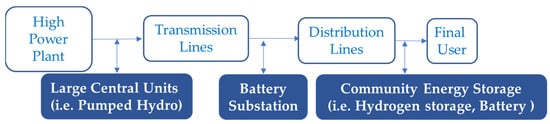
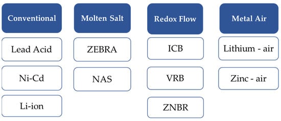
According to Figure 1, both battery and hydrogen storage systems are two feasible options for energy storage at the connection point closest to the customer. This article presents a technical study of current technologies involving batteries and hydrogen storage systems and their uses in the market in an attempt to better understand the path their future developments should take. Then, conventional, molten salt, redox flow and metal-air battery technologies are studied; while regarding hydrogen storage systems, solutions based on compressed hydrogen, liquid hydrogen and metal hydrides storage are analysed in the paper.
The main contributions of the paper are listed below:
- A detailed study of battery and hydrogen storage technologies. The study includes fundamental principles of operation, classification and degree of technological maturity.
- A mathematical model for each technology, that allows to know the state of charge of the storage system in real time. In this way, it is possible to address energy management strategies in plants that combine storage systems of different nature such as hydrogen storage systems and battery systems.
- A technical analysis of all the studied technologies that allows to understand research trends and future possibilities in an attempt to aid in planning deciding policies.
2. Battery: History and technical analysis
2.1. History
As for the history of the different battery technologies, the 19th century was the starting point for conventional battery technologies (including lead acid, lithium ion and nickel cadmium batteries). Furthermore, the first conventional battery technology, rechargeable lead-acid battery, was invented in 1860 [15,16] by the French scientist Gaston Planté, by comparing different large lead sheet electrodes (like silver, gold, platinum or lead electrodes) immersed in diluted aqueous sulfuric acid; experiment from which it was obtained that in a cell with lead electrodes immersed in the acid, the secondary current that flowed through it was the highest and flowed for the longest period of time. Although that first battery did not have a large capacity, it attracted the interest of scientists such as Fauré (who coated lead plates with a paste of water, sulfuric acid and red lead oxide), Volckmar (who replaced the lead sheet with a lead grid) or Sellon (who used lead-antimony grids instead of pure lead grids), so the capacity of these batteries was increased. Nowadays, as a result of the rapid development of the automobile after Second World War, which led to an exponential increase in the production of lead-acid batteries, these are used in various vehicles such as aircraft, submarines or hybrid electric vehicles. Nevertheless, these batteries are still under study and present different challenges such as increasing their power performance or their specific energy [15,16].
On the other hand, the rechargeable Nickel-cadmium (NiCd) battery was created in 1899 by the Swedish chemist Waldemar Jungner. Compared to lead-acid batteries, this battery has drawbacks such as its high initial cost. However, it has other advantages over lead-acid battery such as a lower maintenance, due to higher corrosion resistance [17]. This battery is currently used for portable electronics applications, but one of its major drawbacks is that it is made of toxic materials, so proper management and recycling of those materials is a current challenge for this technology [18].
As for the last group of conventional batteries, experiments for lithium-ion batteries began in 1912, but it was not until 1980 that John B. Goodenough created rechargeable lithium-ion batteries, such as those used in electronic devices around the world [19,20]. Lithium-ion batteries replaced zinc-mercury batteries used up to the moment in medical devices, such as pacemakers, extending the replacement time from two to five years, and improving the survival rate from 75% to 100% [21].
Regarding the history of molten salt batteries, ZEBRA batteries were invented in South Africa and were first applied in 1978. For two decades, it was developed by Daimler-Chrysler and its current production depends on MES-DEA [22]. A few years after the appearance of ZEBRA, in 1983, Tokyo Electric Power Company (TEPCO) and NGK Insulators, Ltd. introduced sodium sulphur (NAS) batteries [23].
As for the history of redox flow batteries (RFBs), Iron-Chromium Batteries (ICBs) were pioneered and studied extensively by NASA in the 70′s–80′s and by Mitsui in Japan [24]. However, the conceptual design of flow batteries was introduced in 1933 in a patent by Pissoort, who described the use of a vanadium redox couple. In the late 1970s, NASA studied flow batteries and considered the Fe-Cr and Fe-Ti redox pair to be the most promising systems. Later, in 1978, Pellegri and Spaziante patented the idea of using vanadium redox salts (without relevant developments), but it was not until 1986 that a group of Australian scientists at the University of New South Wales led by Skyllas-Kazacos achieved the first successful demonstration of a commercial vanadium cell, followed in 1989 by the development of vanadium redox batteries. As for Zinc Bromide (ZNBR) batteries, their concept appeared more than a hundred years ago; however, it was not until 1970–1980 when Exxon and Gould brought the first proposals to practical use [25].
Finally, regarding metal-air batteries, although this technology is receiving more attention recently, their origin dates back to more than twenty years ago, when Abraham et al. in 1996 [26] first presented a rechargeable Li-air battery. Nevertheless, due to the rising costs of lithium and its relative scarcity compared to other materials, various scientists have been working with other materials. Then, Iudice et al. [27] propose aluminium/air batteries in seawater, with the advantage that these batteries are more stable against corrosion.
2.2. Influence. Fundamental principles
2.2.1. Conventional batteries
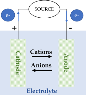
Batteries included in this group are the most common and the most extended in the market, such as Lead-Acid, Nickel-Cadmium (Ni-Cd) and Lithium-ion (Li-ion) batteries. All of them have in common a redox reaction in which one of the electrodes releases electrons, which are used to supply the load in the external circuit and, after that, are carried to the other electrode. The electrode that releases electrons becomes positively charged (and will release cations to the other electrode through the electrolyte), while the electrode that receives electrons becomes negatively charged (and will release anions to the other electrode through the electrolyte), Figure 5, [28,29].
 |
 |
| (a) | (b) |
Figure 5. Cell configuration of a conventional battery during: (a) charge, (b) discharge.
The chemical characteristics of the three types of batteries that have a cell configuration similar to this conventional design are shown in Table 2.
Table 2. Conventional batteries. Characteristics.
|
Battery |
Cell Reaction |
|
Lead-Acid |
Anode: Pb + HSO4−⇄ 4Pb(II)SO4 + H+ +2e− Cathode: Pb(IV)O2 + 3H+ + HSO4− + 2e− ⇄ Pb(II)SO4 + 2H2O Overall cell: PbO2 + Pb+ 2H2SO4 ⇄ 2PbSO4 + 2H2O |
|
NiCd |
Anode: Cd + 2OH− ⇄ Cd(OH)2 + 2e− Cathode: 2NiO(OH) + 2H2O + 2e− ⇄ 2Ni(OH)2 + 2OH− Overall cell: 2NiO(OH) + Cd + 2H2O ⇄ 2Ni(OH)2 + Cd(OH)2 |
|
Li-ion |
Anode: LixC6 ⇄ xLi+ + C6 + xe− Cathode: Li1−xXXO2+xLi++xe−⇄ LiXXO2 Overall cell: LixC6 + Li1−xXXO2 ⇄ LiXXO2+C6 |
2.2.2. Molten salt batteries
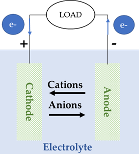
Molten salt batteries (ZEBRA batteries and sodium sulphur batteries) are designed to take advantage of the conductivity of sodium ions, higher than 0.2 S/cm at 260 °C and with a positive temperature gradient. Consequently, they are used in applications where the temperature varies between 270 °C and 350 °C [22].
Both batteries proposals share the cylindrical design which characterizes this kind of batteries and, in both of them, a ceramic electrolyte made from β-Al2O3 (alumina) transfers the sodium ions between the positive and negative electrodes, Figure 6. In this kind of batteries, there is no side reaction, so there is no charge loss due to the ceramic electrolyte and, consequently, their efficiency is high.
The two mentioned proposals can be used in different energy storage applications such as electric vehicles [22,23]; however, both present a series of disadvantages that are a challenge for the development of both technologies. In the case of ZEBRA batteries, due to the high operation temperature, the development of ZEBRA batteries for automotive applications has been affected, since they present self-discharge issues. In this sense, the combination of ZEBRA batteries with Electrochemical Double Layer Capacitors (EDLCs) is being studied as a possible solution [30]. On the other hand, NAS battery also presents a high operation temperature that reduces its efficiency, moreover, the solid electrolyte can become brittle and break during operation, which can result in an increased risk of fire and explosion due to the penetration of molten sodium through the cell. In this sense, the use of a ceramic electrolyte and molten electrodes in this kind of batteries presents different challenges such as increasing the safety of their operation or reducing their operating temperature, which limit the applications of this technology [31].
Despite their drawbacks, these kinds of batteries have lifetime and specific energy three and four times respectively, as higher as conventional batteries. In addition, they can provide power peaks in less than 30 s, so they are used in applications where the quality of the power supply is the main decision factor.
The main features of this kind of batteries are shown in Table 3.
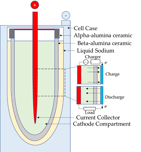 Figure 6. Cell configuration of molten salt batteries.
Table 3. Molten Salt batteries. Characteristics.
|
Battery |
Cell Reaction |
|
ZEBRA |
Anode: Molten sodium (Na) Cathode: Ni and NaCl impregnated with NaAlCl4 Overall cell: NaAlCl4 + 3Na ⇄ 4NaCl + Al |
|
NAS |
Anode: Sodium (Na) Cathode: Sulfur (S) Overall cell: 2Na + xS ⇄ Na2Sx |
2.2.3. Redox Flow Batteries
The two groups of batteries presented so far have well-defined applications based on their cell structure (conventional batteries for portable applications and molten salt batteries for applications requiring high quality power supply).
Nevertheless, none of these previous batteries accomplishes the requirements of the large-scale grid. First, at the grid connection line (a huge physical infrastructure, with almost no storage capability) grid storage is vital because it must uncouple oscillating customer demand from generation, which has a clear fluctuating character in the case of renewable energy sources.
Additionally, grid storage must be able to separate power from energy, tolerate a high number of charge/discharge cycles, to have good round-trip efficiency, to exhibit fast response to load or input changes, and all at reasonable capital costs [32].
Based on the above, a new cell design (Redox Flow Batteries, RFBs are also called Regenerative Fuel Cells, RFBs) was thought of where the reactants are not stored inside the electrode itself (as in previous battery designs), but are dissolved in the electrolyte solution and stored in external tanks, Figure 7, [33]. Then, additional balance-of-plant devices (pump, level sensors, etc.) are needed to make the liquid electrolyte flow. In addition, an Ion Exchange Membrane (IEM) separates the anolyte and catholyte solutions and allows for the transport of charge-carrying species. Furthermore, the IEM can act as an effective barrier to prevent permeation of active species and improve the ionic selectivity of the system by reducing the crosstalk of active species and addressing important drawbacks such as self-discharge or loss of capacity [34].
Figure 7. Cell configuration of redox flow batteries (“Me” refers to reactant dissolved in the electrolyte solution).
Additionally, thanks to the fact that there is no physical transfer of material across the electrode/electrolyte interface, the lifetime of this type of batteries is not directly influenced by the depth-of-discharge (DOD), as it is the case in conventional rechargeable batteries. In this type of batteries, the power is determined by the number of stacked cells and the stored energy depends on the reactants: their nature, their concentration, and the size of tanks. In addition, for one of the batteries of this technology (Zinc Bromide battery), one of the potential risks is the formation of zinc dendrites, which will start their growth if the critical potential value is reached (at that moment, the equilibrium state will be broken and the growth of zinc dendrites will start). Furthermore, the growth of zinc dendrites will be accelerated in case the current density at the electrode surface is high and non-uniform [35].
There are three different electrolytes that form the basis of existing flow batteries designs, currently in demonstration or in development of large-scale projects, which are: Iron-Chromium (IC), Vanadium (VRB) and Zinc Bromide (ZNBR). Within the ZNBR batteries, it is possible to find other variants such as Polysulphide Bromide (PSB), in which the role played by zinc in the anode side is replaced by polysulphide.
The main features of the three types of batteries classified as RFB are shown in Table 4.
Table 4. Redox Flow Batteries. Characteristics.
|
Battery |
Cell Reaction |
|
ICB |
Anode: Cr2+ ⇄ Cr3+ + 1e− Cathode: Fe3+ + 1e− ⇄ Fe2+ |
|
VRB |
Anode: V 4+ ⇄ V5+ + 1e− Cathode: V 3+ + 1e− ⇄ V2+ |
|
ZNBR |
Anode: Zn ⇄ Zn2+ + 2e− Cathode: Br2 + 2e− ⇄ 2Br− |
2.2.4. Metal-air batteries
In order to achieve batteries with higher specific energy and lower maintenance than conventional rechargeable batteries, metal-air batteries were developed. These batteries have an open cell structure, i.e., on the one side the electrode is a metal (lithium or zinc) and, on the other side, the electrode is oxygen (regarding the different designs of the cell structures studied along the paper, this last group of metal-air batteries have a cell design that likely approach to fuel cells design), taken from the air, for the reaction to take place. Air is introduced through a channels-based structure and a catalyst ensures oxygen reduction. The intermediate electrolyte allows the flow of ions, and its nature establishes the type of battery: aqueous, non-aqueous, hybrid and solid-state metal–air batteries. In the case of aqueous and hybrid electrolyte, a metal ion conducting polymer membrane is required [36]. The configuration of the different metal–air batteries is shown in Figure 8. Although, there are primary (non-rechargeable) metal–air batteries, such as aluminium–air (Al-air) or magnesium–air (Mg–air) batteries, our study will be focused on secondary (rechargeable) batteries: lithium–air (Li–air) and zinc–air batteries (Zn–air) [37] as shown in Table 5.
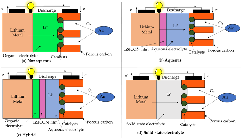
Figure 8. Metal–Air batteries cell configuration.
Table 5. Metal–Air Batteries. Characteristics.
|
Battery |
Cell Reaction |
|
Li-Air |
Anode: Li ⇄ Li+ + 1e− Cathode: Li+ + 1e− + O2⇄ LiO2 |
|
Zn-Air |
Anode: Zn + 4OH− ⇄ Zn(OH)42− + 2e− Cathode: 1/2O2 + H2O + 2e− ⇄ 2OH− |
2.3. Technical analysis
2.3.1. Conventional batteries
Currently, the battery industry relies on lithium for its most efficient batteries, but this element is expensive and geographically unsustainable, as most of the current lithium mines are not in ideal locations for the US or Europe. This may be the reason why sodium batteries are slowly being developed to have the same energy capacity as their lithium counterparts, as these batteries are much cheaper, and the required sodium can simply be extracted from the ocean or practically anywhere, given that it is the sixth most common element in the Earth’s crust [38].
In the beginning, lithium batteries were tested out with a bunch of different cathodes, before settling on the first commercial cathode: magnesium dioxide. Now that both anode and cathode materials have reached a plateau of sorts, the challenge is to further improve the specific energy of batteries and make them more affordable, which will require a lot of effort [39].
From a technical point of view, Li-ion batteries can reach a high lifetime of 1000–10,000 cycles [2,40], ~8,000 cycles [41], ~10,000 cycles [42], while NiCd batteries can reach a lifetime of >2000 cycles [2], 2,000–2,500 cycles [40,42] and, on the other hand, lead-acid batteries can only reach a lifetime of 500–1500 cycles [40], <2000 cycles [41], ~2500 cycles [42]; Li-ion batteries have the greatest specific energy (80–200 Wh/kg [2], 75–200 Wh/kg [40,41], ~200 Wh/kg [42], 100–265 Wh/kg [43]), compared to lead-acid batteries (30–50 Wh/kg [40], ~50 Wh/kg [42], 30–40 Wh/kg [43]) and NiCd batteries (50–75 Wh/kg [2,43], 45–80 Wh/kg [40], 55–75 Wh/kg [42]); and Li-ion batteries exhibit higher average round-trip efficiency (<97% [2], 85–95% [40], 90–95% [41,44], 85–90% [42], 92–95% [43]) than lead-acid batteries (80% [2], 60–95% [40], ~80% [41], 80–82% [43], 70–90% [44]) and NiCd batteries (60–91% [40], 72% [43]). Furthermore, Li-ion batteries have higher specific power (500–2000 W/kg [2], 400–1,200 W/kg [40], 150–3,000 W/kg [44]) than Ni-Cd batteries (150–300 W/kg [40]) and lead-acid batteries (75–300 W/kg [40,44]); and for Li-ion batteries a wider power range can be found (0–50 MW [40], 0–100 MW [44] for Li-ion batteries, compared to 0–40 MW [40] for NiCd batteries and 0–20 MW [40], 0–40 MW [44] for lead-acid batteries) although these three batteries can have a wide power range.
Table 6 shows a summary of a technical comparison between the different conventional batteries.
Table 6. Comparison of the main technical parameters of the different conventional batteries.
|
Parameters |
Lead-Acid |
Li-Ion |
NiCd |
|
Efficiency (%) |
60–95 |
85–97 |
60–91 |
|
Life cycles |
500–2500 |
1000–10,000 |
2000–2500 |
|
Specific energy (Wh/kg) |
30–50 |
75–265 |
45–80 |
2.3.2. Molten Salt Batteries
From a technical point of view, ZEBRA batteries can reach a lifetime from 2600 cycles [42] to 4000 cycles [45], while NAS batteries can reach a lifetime of 2500–4000 cycles [40], 2500–4500 cycles [42,44]; both batteries have similar operating temperature (265–350 °C [45], 270–350 °C [42] for ZEBRA batteries and 250–350 °C [2], 300–350 °C [46] for NAS batteries) and high specific energy that is higher for NAS batteries (150–240 Wh/kg [2,40], 100–240 Wh/kg [44]) than for ZEBRA batteries (approximately 100–120 Wh/kg [45,47]). However, NAS batteries have a higher round-trip efficiency than ZEBRA batteries (80–90% [2], 75–90% [40], 75–85% [42,44] vs. 70.7–80.9% [45]). On the other hand, NAS batteries present slightly higher specific power (150–230 W/kg [2], 100–230 W/kg [44]) than ZEBRA batteries (150–200 W/kg [2]).
A summary of a technical comparison between the different molten salt batteries is shown in Table 7.
Table 7. Comparison of the main technical parameters of the different molten salt batteries.
|
Parameters |
ZEBRA |
NAS |
|
Efficiency (%) |
70.7–80.9 |
75–90 |
|
Life cycles |
2600 – 4000 |
2500–4500 |
|
Specific energy (Wh/kg) |
100–120 |
100–240 |
2.3.3. Redox Flow Batteries
From a technical point of view, ZNBRs present the highest specific energy (30–85 Wh/L [2], 30–60 Wh/L [44], 30–50 Wh/kg [40,44]) compared to VRBs (10–50 Wh/kg [2], 10–35 Wh/kg [40], 10–30 Wh/kg [44], 20–70 Wh/L [44]) and ICBs (15.8 Wh/L [22]); ICBs present lower round-trip efficiency (76.3–79.6% [48]) than VRBs (75–85% [2], 85–90% [40], 65–85% [44]) and slightly higher than ZNBRs (65–70% [2], 65–85% [40], 60–65 % [42], 70–80% [44]) and a higher operating temperature (40–60 °C) than VRBs and ZNBRs (10–40 °C) [25,49]. Finally, redox flow batteries present a high lifetime: 10,000–16,000 cycles [2], 12,000–18,000 cycles [40], >13,000 cycles [42], 10,000–13,000 cycles [44] for VRBs and >2000 cycles [40], 2000–10,000 cycles [44] for ZNBRs. Table 8 shows a summary of a technical comparison between the different RFBs.
Concerning current trends in redox flow batteries, RFBs can be found to present challenges such as research on the flow management and parameter estimation [50]. Furthermore, the possibility of modifying VRB systems in order to increase the density of the active material and, above all, to find replacements for vanadium, a relatively rare material, is currently being studied [25]. Another challenge faced by redox flow batteries are the limitations associated with IEMs, such as their high costs, safety concerns due to the evolution of toxic intermediates, or temperature limitations due to corrosive gases released at temperatures above 150 °C [51].
Table 8. Comparison of the main technical parameters of the different RFBs.
|
Parameters |
ICB |
VRB |
ZNBR |
|
Efficiency (%) |
76.3–79.6 |
65–90 |
60–85 |
|
Life cycles |
- |
100,000–18,000 |
2000–10,000 |
|
Specific energy |
15.8 Wh/L |
20–70 Wh/L 10–50 Wh/kg |
30–85 Wh/L 30–50 Wh/kg |
2.3.4. Metal-Air Batteries
The main characteristics of these batteries are good thermal stability in the range of 30–105 °C, high specific energy of 250–300 Wh/kg and 75% efficiency [52], as well as low pollution level (so they can be considered an environmentally friendly option) [37,53] and low cost, as a consequence of the abundance of raw materials [54]. However, the main drawback of these batteries is their reduced lifetime [1000 cycles] due to the precipitation of carbonate inside the electrode pores in the electrode open to the air [52].
Although these batteries have high potential, they have not fulfilled it, because this technology presents challenges with the metal anode, the air cathode, the electrolyte and its short lifetime. Therefore, before this technology becomes a real option in electric vehicles or electrochemical energy storage, it is a challenge to achieve, through research and development, a specific energy of 500 Wh/kg and a lifetime of more than 1000 cycles [53].
Table 9 shows a summary of a technical comparison between the different battery technologies analysed in the paper.
Table 9. Summary of the technical parameters of the batteries studied in the paper.
|
Comparison of Battery Storage Technologies |
||||
|
Characteristics |
Conventional Batteries |
Molten Salt Batteries |
RFBs |
Metal-Air Batteries |
|
Efficiency (%) |
60–97 |
70.7–90 |
60–90 |
75 |
|
Life cycles |
500–10,000 |
2500–4000 |
2000–18,000 |
<1000 |
|
Specific energy (Wh/kg) |
30–200 |
100–240 |
10–50 |
250–300 |
3. Hydrogen Fuel: Ways to storage
3.1. History
As for hydrogen storage technologies history, there are different starting points. In the case of compressed hydrogen storage technology, the use of this technique is not new. In Teeside, England, 5 MPa compressed hydrogen was stored in caverns and, in France, between 1956–1972, an aquifer was used to store a synthetic gas of 50–60% hydrogen [59]. However, as subway hydrogen storage systems were too limited to be implemented on a large scale [60], coupled with a growing interest in hydrogen in the 1970s as a result of the oil crisis [61], led to the research and development of hydrogen storage tanks, whose vessels were initially made of aluminium; however, as they were not strong enough, vessel materials were changed to a carbon-fibre composite [62].
As for the liquid hydrogen histort, although hydrogen began to be stored in liquid form in the 1940s, it was not until the 1980s and 1990s that liquid hydrogen began to be studied seriously because of its high potential [62].
On the other hand, the origins of metal hydrides storage technology date back to 1810, when Luigi Sementini, a professor of chemistry in Naples, published a report of a new method for extracting potassium and sodium. Many years later, Thomas Graham became interested in metal hydrides because he saw in this technology a new aspect of his studies on gas diffusion and extended the research with metals from platinum to palladium to observe the high adsorption of hydrogen. However, it was not until the laboratory work of Winkler (whose work led to the discovery of a larger number of metal hydrides), Moissan and others, that industrial developments became possible. Thus, in 1905, Bitterfeld claimed in a patent that molten calcium in an iron vessel rapidly absorbed hydrogen, and a 1943 patent established the idea of hydrogen as a fuel cell in a chemical energy package thanks to metal hydrides [63].
In the case of complex hydrides storage technology history, although they are known since 19th century (there is a report [64] on metal amides from 1809), it was not until the 1960s when they were started to be studied as potential hydrogen storage materials [64]. Many years later [65], in the mid-nineties, Bogdanovic discovered hydrogen uptake and release for sodium alanate, NaAlH4, at moderate conditions. Later, in 2002 [65], P. Chen discovered reversible nitrogen-based complex hydrides and, in 2003, A. Züttel, and co-workers were the first to start investigating tetrahydridoboranates, such as LiBH4, [65].
Finally, regarding alkalimetal+H2O technology, it is far from be implemented, as it is still in the development phase. It was in 2003 that Li et al. generated hydrogen from a reaction between sodium borohydride (NaBH4), with a gravimetric density of 10.6 wt. %, and water at an operating temperature of 60 °C [66].
3.2. Influence. Fundamental Principles
3.2.1. Compressed Hydrogen Storage
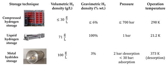
Compressed hydrogen storage is currently the most common method of hydrogen storage. Typically, hydrogen gas is pressurized in a metal-composite tank at a given pressure, which can vary widely depending on the tank and its use, from 200 bar to 700 bar [67]. Higher pressures have been used for the storage of gaseous hydrogen in order to achieve volumetric densities close to that of liquid hydrogen, 70.8 g/L (about 1000 times the volumetric density of hydrogen gas at ambient pressure and temperature).
3.2.2. Liquid Hydrogen Storage
To obtain liquid hydrogen, it is necessary to reach the hydrogen critical temperature, 33 K, i.e., almost to absolute zero. In this sense, liquid hydrogen storage tanks are at ambient pressure and a temperature of 21.2 K; in addition, the process to obtain it is a Joule-Thomson cycle in which gaseous hydrogen is first compressed, then cooled in a heat exchanger and finally expanded in a valve isenthalpically to form liquid. Although theoretically only 3.23 kWh/kg of energy are needed to liquefy hydrogen, in the practice, this values are as high as 15.2 kWh/kg, i.e., half of the Lower Heating Value (LHV) of hydrogen (33.36 kWh/kg) [68].
3.2.3. Metal Hydrides Storage
Metal hydrides (MHx) are the most technologically relevant class of hydrogen storage materials, as they can be used in a variety of applications at ambient pressure and temperature. In this case, gaseous hydrogen molecules are absorbed by the material in the solid state to form metallic hydrogen compounds and the hydrogen is distributed compactly throughout the metal lattice.
|
Metal + H2 ⇄ MxHy + Heat |
(1) |
The reaction is reversible and exists as an equilibrium state under certain conditions of pressure and temperature. In other words, by changing the conditions, the reaction can move in the forward or backward direction. The heat on the right-hand side indicates that heat or energy is released when the MHx is formed (during the charging process), and therefore heat must be put into the system to release the hydrogen from the metal hydride (during the discharging process).
3.2.4. Physisorption
The physisorption of gas molecules, Figure 10, onto the surface of a solid, is the result of resonant fluctuations of charge distributions (i.e., Van der Waals interactions, composed of two terms: an attractive and a repulsive one, which decrease with distance, , in a ratio of and , respectively). For this reason, physisorption is weak, and significant physisorption can only be observed at low temperatures (<273 K) [68]. Porous materials are a potentially promising storage technology for absorbing hydrogen, since they can reach a high capacity and can release the gas reversibly [69,70]. Among all porous materials, porous carbon materials and Metal Organic Frameworks (MOFs) are known to be promising. This technology has advantages such as low cost of materials, high surface area, faster charging and discharging processes or the possibility of mitigating thermal management issues. However, the need for low pressure and temperature, the weight of carrier materials and low gravimetric and volumetric density make the application of this technology difficult. These disadvantages have meant that experiments with this technology have been unsatisfactory; and it is far from be widely used, being only possible to find applications in small-scale experiments [70].
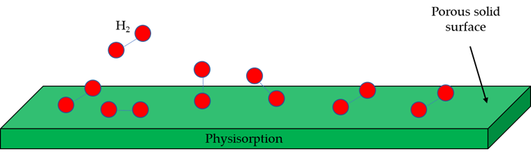
Figure 10. Physisorption process.
3.2.5. Complex Hydrides Storage
Complex hydrides are generally solid ions composed of cations bonded to complex anion groups (centered on Al, B or N, among others), such as AlH4−, NH2− or NH2−, through a covalent bond, in which hydrogen participates. Due to slow kinetics reactions, decomposition of complex metal hydrides take place at high temperatures (in the case of LiBH4, it takes place at 500 °C), while hydriding reaction take place at high pressures (up to 200 MPa) because of a faster reaction rate [71]. Figure 11 shows physical process of complex hydrides.

Figure 11. Complex hydrides process.
3.2.6. Alkalimetal+H2O
This technology combines a particular case in complex hydrides (which it is made, for this hydrogen storage technique, from alkali or alkaline earth cations bonded to the complex anions introduced above) with water to cause a simple reaction in which hydrogen is obtained as a product [72]. Figure 12 shows the physical process of this technology.

Figure 12. Alkalimetal+H2O physical process.
3.3. Technical Comparison
From a technical point of view, for compressed hydrogen storage technologies there are currently different types of compressed hydrogen tanks: type I are all-metal tanks in which hydrogen is usually stored between 200 and 300 bar (this type of tank has a low gravimetric density of about 1 wt. % due to the materials from which it is made); type II are metal tanks with their cylindrical part reinforced by Carbon Fibre Reinforced Polymer (CFRP) composite material, which allows this kind of tank to reach a slightly higher storage capacity than type I tanks (both type I and type II tanks are used in stationary applications); type III are tanks that have a fully CFRP-wrapped metal liner; type IV tanks are similar to type III tanks except that their liner is polymeric and not metallic (type IV tanks have reached a gravimetric density of 4.2 wt. %, because these tanks are made of lighter materials, and a volumetric density of 24 g/L at 700 bar); and, finally, type V tanks are in the development phase and are completely made of composite materials (unlined structures). Among these tanks, the most common and widely used are type III and type IV tanks due to their light weight and fatigue resistance, as well as the fact that their nominal working pressure is usually 350 to 700 bar (considerably higher than type I and type II tanks), which explains the use of these type of tanks in the automotive sector or for industrial purposes [73–75]. In addition, the industry has set a target of storing compressed hydrogen in 700 bar tanks, whereby a 6 wt. % gravimetric density and a 30 g/L volumetric density can be achieved [69]; in comparison, a 350 bar hydrogen tank has a gravimetric density of 5.5 wt. % and a volumetric density of 17.6 g/L [76]. Furthermore, this technique has the advantage that it can be used to repeatedly (and frequently) charge and discharge the hydrogen in the tank up to a lifetime of 20 years [77]. In fact, in the case of type III tanks, they can be charged and discharged up to 5122 times before their lifetime comes to an end [78]. Although this technique consumes 2.21 kWh/kg for an isothermal compression from 0.1 to 80 MPa, this value is much lower than that of other techniques such as hydrogen liquefaction [69].
Regarding liquid hydrogen storage, this technique has the advantage of a high volumetric density, 71 g/L, compared to compressed gaseous hydrogen storage tanks [79], but the disadvantage of having to deal with boiloff ratio, which can be 0.1 to 0.2% per day of the total liquid hydrogen depending on the ratio of area to volume, so in order to reduce these losses, it is necessary to reduce the area, in proportion, more than the volume [80]. Furthermore, according to the U.S. Department of Energy (DOE), liquid hydrogen storage tanks lifetime are set at 30 years by 2025 [81].
As for metal hydrides storage technology, current metal hydride tanks can reach an operating charge pressure of more than 100 bar. However, for practical and economic reasons, less than 30 bar is preferred; on the other hand, the discharge process must be carried out at a pressure of about 2 bar and at a temperature below 100 °C. Although this technology provides a high volumetric density, 100 g H2/L, its maximum gravimetric density is below 7 wt. %, but in practice, it is usually around 3 wt. %. Although this storage method has efficiency of 88% [82], its main disadvantage is the lifetime (up to 1500 cycles or 10 years) [83].
The storage materials to be combined with hydrogen in this technology include Ni, Co, Al, Mn, Sn, Cr, Fe, V, Mg, among others [82,84].
On the other hand, for the complex hydrides storage technology, high volumetric and gravimetric densities can be found (which will be different based on the material used). For example, for ammonia borane, NH3BH3, a 19.6 wt. % and a 150 g/L gravimetric and volumetric densities, respectively, are found [85], while for Mg2FeH6, a 5.5 wt. % and a 150 g/L gravimetric and volumetric densities, respectively, are found [86]. Furthermore, this technology has a long lifetime, with more than 5000 adsorption/desorption cycles [65]. Although these densities made complex hydrides storage a serious option to store large amounts of hydrogen (up to 700 kg [65]), this technology has to cope with issues such as thermal management (heat removal at several hundred of degrees) during refuelling [85].
Finally, for Alkalimetal+H2O technology, the materials that can be used have a wide range for both volumetric and gravimetric densities, varying from 25.86 g/L for CsH to 138.08 g/L for BeH2 in the case of volumetric density, and from 0.75 wt. % for CsH to 18.39 wt. % for LiBH4 in the case of gravimetric density [72]. Furthermore, an advantage of this technology over complex hydrides is a lower operating temperature, for example, the decomposition temperature of NaBH4 to obtain hydrogen is 565 °C [72], while for the reaction of this material with water, the operating temperature is just 60 °C [66]. Due to their higher gravimetric and volumetric densities, together with a higher stability of borohydrides, some of the most promising materials in this technology (still under research), LiBH4, NaBH4 or Ca(BH4)2, among others [72], can be found.
Once the different hydrogen storage techniques have been analysed, a comparison has been made between gravimetric and volumetric densities for the different hydrogen storage alternatives, Figure 13 (where alkali metals are treated as a particular case of complex hydrides, but in the case of a reaction with water, the operating temperature is much lower). In addition, Table 10 gives a technical comparison between the different commercial hydrogen storage technologies discussed in the paper.
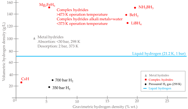
Figure 13. Alternatives for hydrogen storage: technical comparative.
Table 10. Summary of technical parameters of commercial hydrogen storage technologies.
|
Technology |
Lifetime |
Efficiency |
Volumetric Density |
|
Compressed hydrogen storage |
20 years |
90–95% |
30 g/L |
|
Liquid hydrogen storage |
30 years (2025 DOE target) |
75–80% |
70.8 g/L |
|
Metal hydrides storage |
10 years |
85–90% |
100 g/L |
|
Complex hydrides storage |
30 years |
- |
150 g/L |
4. Battery and hydrogen storage technologies applications
Regarding the possible applications of the different energy storage systems that have been previously studied, different applications in a wide range of power can be found.
First, in the case of batteries, different applications depending on the technology that is studied can be found. For example, regarding conventional batteries applications, for lead-acid batteries applications such as household Uninterruptible Power Supply (UPS) of the order of few Wh or such as submarine power or load-levelling of the order of several MWh can be found [87], while for Li-ion batteries applications such as portable electronic devices or electric vehicles (EVs) can be found [88] and finally for NiCd batteries applications such as aviation safety, telecommunication network or off-grid PV can be found [47].
As for the applications of molten salt batteries, ZEBRA batteries can be used in electric and hybrid electric vehicles or energy storage applications, while NAS batteries can be used for wind power integration or high-value grid services [46].
On the other hand, regarding the applications of RFBs, different examples such as UPS, interseasonal storage, load levelling function or electric and hybrid vehicles, especially those of large dimensions (due to the low specific energy) [50] can be found.
Regarding the hydrogen storage technologies, compressed hydrogen storage technique can be used in different applications, such as small-scale storage, so it can be used in different vehicles like cars and buses [82], as a storage system in a microgrid [89] or even stored in a 700 bar tank in a hydrogen-powered snow groomer [90].
On the other hand, although it is currently a problem to implement liquid hydrogen storage in hydrogen-powered automotive applications, it is used in aerospace engineering [91] and in marine applications as temperature sensors [92]. One future direction for this technology is to combine with compressed hydrogen storage technology to obtain cryocompressed hydrogen storage tanks, which are capable of increasing volumetric density from 70 g/L at 1 atm to 87 g/L at 237 atm [62].
As for metal hydrides storage, this technology can be found to be used in different applications such as stationary and mobile, heat storage, automotive, railroads or a high pressure metal hydride tank (>875 bar) for refuelling fuel cell vehicles [84,93].
Finally, complex hydrides storage technology can be used in different applications such as on-board hydrogen storage, stationary storage, or portable power [71].
If a summary study for the application field of each and every storage technique (for both hydrogen and battery storage techniques) is done, Figure 14, it can be found that none of the technologies that have been analyzed can be used in the order of bulk power (greater than 100 MW), what explains why large scale energy storage is not currently available; however, they can be used in other applications such as UPS Power Quality (for example, lead acid batteries, ZEBRA batteries or redox flow batteries), in vehicles (such as ion lithium batteries, hydrogen composite cylinders or potentially metal-air batteries) or as a grid support (for example, compressed hydrogen composite cylinders or lead acid batteries, among others).
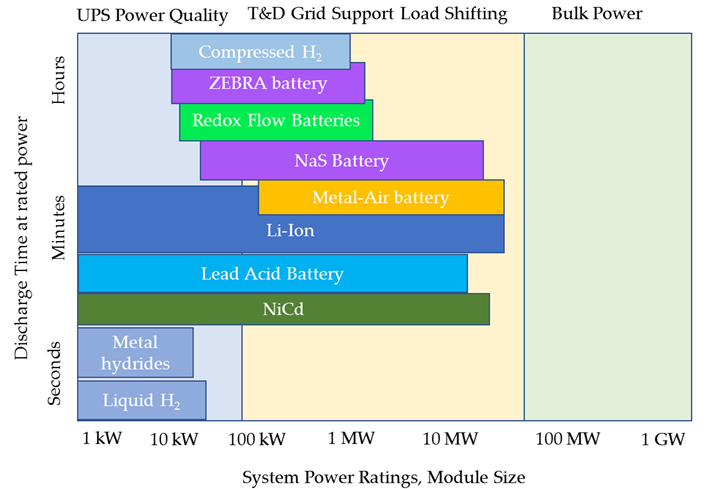
Figure 14. Application field for each technology
5. Why and when choose one energy storage system over another
Currently, there are two major green energy storage alternatives that people are considering for small and medium-sized applications: batteries and hydrogen storage. It is obvious that batteries are the most widespread (computers, mobile phones, vehicles), while hydrogen storage is used in lesser-known applications like heavy transport (trucks, buses, railways, submarines or spy-planes), or renewable sources-based microgrids.
In order to select the best choice, the first comparison to be made is the lifetime of the storage systems. For example, for a hydrogen storage system, a lifetime of 5122 cycles can be found for a type III compressed hydrogen tank [78], which is a longer lifetime than most of the batteries (only redox flow batteries and some lithium-ion batteries can present better behaviour in terms of lifetime), while for a metal hydride tank, the lifetime is up to 1500 cycles [83], which is only competitive against some battery technologies such as metal-air batteries or lead-acid batteries. On the other hand, regarding storage systems round trip efficiency, for metal hydride tanks, efficiencies of 88% can be found [82]. Although some batteries can be found with higher round-trip efficiency, this storage system is competitive against battery ones. However, contrary to battery storage systems (which convert electrical energy into chemical energy to store energy in the charging process and, in the discharging process, batteries convert chemical energy into electrical energy), a hydrogen storage system does not convert the electrical energy into chemical energy in the charging process by itself (as well as it does not convert chemical energy into electrical energy in the discharging process), since a device is needed to produce hydrogen from electrical energy. If green hydrogen (the one obtained via renewable powered electrolysis) is required to be produced, it is necessary to use an electrolyser to produce hydrogen. For an alkaline electrolyser (the most developed electrolysis technology) this process has efficiencies between 43–66% [94]. Furthermore, once the hydrogen is stored in the tank, to obtain electrical energy from it, another device is needed; if that device is a polymeric electrolyte membrane fuel cell (such as the one used to discharge the metal hydride tank in the article), its efficiency is around 45%. In this sense, for the whole process (production, storage and conversion into electricity), even if the energy losses associated with storage process (which in the case of metal hydride tanks, are about 12% of the stored energy), the overall efficiency is 20–31%, while for battery storage systems, the round-trip efficiency varies from 60% to 95%, i.e., between 2 and 4.75 times the hydrogen process efficiency (even if the losses associated with storage process are ignored). In addition, since the fuel cell efficiency is 45% (i.e., much lower than the whole round-trip efficiency of battery storage systems), the equivalent energy in a hydrogen storage tank needs to be considerably higher than the energy stored in a battery in order to obtain the same electrical energy.
Finally, although hydrogen systems (i.e., apart from the hydrogen storage, an electrolyser to produce hydrogen and a fuel cell to convert chemical energy from hydrogen into electric energy are needed) hardly can compete with batteries in terms of overall efficiency, in terms of specific energy density, hydrogen has no rival. Hydrogen has a lower heating value of 33.36 kWh/kg, i.e., more than a hundred times batteries specific energy. Therefore, hydrogen storage systems can complement batteries and be used in renewable sources-based plants as a long-term storage system, while batteries would act as short and medium-term storage system.
Author Contributions: Conceptualization, J.R. and F.S.; methodology, F.S. and J.R.; software, F.J.V.; validation, F.J.V.; formal analysis, J.R. and F.S.; investigation, J.R. and F.J.V.; resources, J.M.A.; data curation, F.J.V.; writing—original draft preparation, J.M.A., F.S. and J.R; writing—review and editing, J.R. and F.S.; visualization, F.J.V.; supervision, F.S. and J.M.A.; project administration, J.M.A.; funding acquisition, J.M.A. All authors have read and agreed to the published version of the manuscript.
Funding: This research was funded by 1) Spanish Government, grant Ref: PID2020-116616RB-C31, 2) Andalusian Regional Program of R+D+i, grant Ref: P20-00730, and 3) FEDER-University of Huelva 2018, grant Ref: UHU-1259316.
Institutional Review Board Statement: Not applicable
Informed Consent Statement: Not applicable
Data Availability Statement: Not applicable.
Conflicts of Interest: The authors declare no conflict of interest.
Nomenclature
|
CFRP |
Carbon Fibre Reinforced Polymer |
|
DOD |
Depth Of Discharge |
|
DOE |
Department Of Energy |
|
ESS |
Energy Storage Systems |
|
IEM |
Ion-Exchange Membrane |
|
LHV |
Lower Heating Value |
|
MHx |
Metal Hydride |
|
O&M |
Operation and Maintenance |
|
PEM-FC |
Polymeric Electrolyte Membrane-Fuel Cell |
|
RES |
Renewable Energy Sources |
|
RFB |
Redox Flow Battery |
|
SMES |
Superconducting Magnetic Energy Storage |
|
SOC |
State Of Charge |
|
ZEBRA |
Zero Emission Battery Research Activity |
References
- Russo, M.A.; Carvalho, D.; Martins, N.; Monteiro, A. Forecasting the inevitable: A review on the impacts of climate change on renewable energy resources. Energy Technol. Assess. 2022, 52, 102283. https://doi.org/10.1016/J.SETA.2022.102283.
- Zhang, Z.; Ding, T.; Zhou, Q.; Sun, Y.; Qu, M.; Zeng, Z.; Ju, Y.; Li, L.; Wang, K.; Chi, F. A review of technologies and applications on versatile energy storage systems. Sustain. Energy Rev. 2021, 148, 111263. https://doi.org/10.1016/J.RSER.2021.111263.
- Communication, L.S. The smart grid: An introduction. Smart Grid Electr. Power Transm. 2011, 1–45. https://doi.org/10.1002/9781119521129.ch15.
- Walker, T.J. EPRI Intelligrid/Smart Grid Demonstration Joint Advisory Meeting. System 2010, 1–16.
- Eustis, C.; Gyuk, I. Energy Storage Safety Strategic Plan Acknowledgements. 2014. Available online: https://vdocuments.net/energy-storage-safety-strategic-safety-strategic-planenergy-storage-safety-strategic.html?page=1 (accessed on 25 July 2022).
- AL Shaqsi, A.Z.; Sopian, K.; Al-Hinai, A. Review of energy storage services, applications, limitations, and benefits. Energy Rep. 2020, 6, 288–306. https://doi.org/10.1016/J.EGYR.2020.07.028.
- Pershaanaa, M.; Bashir, S.; Ramesh, S.; Ramesh, K. Every bite of Supercap: A brief review on construction and enhancement of supercapacitor. Energy Storage 2022, 50, 104599. https://doi.org/10.1016/J.EST.2022.104599.
- Fiore, M.; Magi, V.; Viggiano, A. Internal combustion engines powered by syngas: A review. Energy 2020, 276, 115415. https://doi.org/10.1016/J.APENERGY.2020.115415.
- Rullo, P.; Braccia, L.; Luppi, P.; Zumoffen, D.; Feroldi, D. Integration of sizing and energy management based on economic predictive control for standalone hybrid renewable energy systems. Energy 2019, 140, 436–451. https://doi.org/10.1016/J.RENENE.2019.03.074.
- Piccolino, M. The bicentennial of the Voltaic battery (1800-2000): The artificial electric organ. Trends Neurosci. 2000, 23, 147–151. https://doi.org/10.1016/S0166-2236(99)01544-1.
- Kurzweil, P. Gaston Planté and his invention of the lead-acid battery-The genesis of the first practical rechargeable battery. Power Sources 2010, 195, 4424–4434. https://doi.org/10.1016/J.JPOWSOUR.2009.12.126.
- Kandeeban, R.; Saminathan, K.; Manojkumar, K.; Dilsha, C.G.; Krishnaraj, S. Battery economy: Past, present and future. Today Proc. 2019, 48, 143–147. https://doi.org/10.1016/J.MATPR.2020.04.238.
- Mitali, J.; Dhinakaran, S.; Mohamad, A.A. Energy storage systems: A review. Energy Storage Sav. 2022. https://doi.org/10.1016/J.ENSS.2022.07.002.
- Winter, M.; Brodd, R.J. What are batteries, fuel cells, and supercapacitors? Rev. 2004, 104, 4245–4269. https://doi.org/10.1021/cr020730k.
- Ruetschi, P. Review on the lead-acid battery science and technology. Power Sources 1977, 2, 3–120. https://doi.org/10.1016/0378-7753(77)85003-9.
- Pavlov, D. Lead-acid batteries : Science and Technology : A Handbook of Lead-Acid Battery Technology and Its Influence on the Product; Elsevier: Amsterdam, The Netherlands, 2011, p. 722.
- Industrial Batteries 101 n.d. Available online: http://site.ieee.org/fw-pes/files/2018/07/Industrial-Batteries-101-IEEE-PES-Ft-Worth.pdf (accessed on 25 April 2022).
- Johnson, S.C.; Todd Davidson, F.; Rhodes, J.D.; Coleman, J.L.; Bragg-Sitton, S.M.; Dufek, E.J.; Webber, M.E. Selecting Favorable Energy Storage Technologies for Nuclear Power. Storage Hybrid. Nucl. Energy Techno-Econ. Integr. Renew. Nucl. Energy 2019, 119–175. https://doi.org/10.1016/B978-0-12-813975-2.00005-3.
- Sarma, D.D.; Shukla, A.K. Building better batteries: A travel back in time. ACS Energy Lett. 2018, 3, 2841–2845. https://doi.org/10.1021/acsenergylett.8b01966.
- Xie, J.; Lu, Y.C. A retrospective on lithium-ion batteries. Commun. 2020, 11, 9–12. https://doi.org/10.1038/s41467-020-16259-9.
- Scrosati, B. History of lithium batteries. Solid State Electrochem. 2011, 15, 1623–1630. https://doi.org/10.1007/s10008-011-1386-8.
- Dustmann, C.H. Advances in ZEBRA batteries. Power Sources 2004, 127, 85–92. https://doi.org/10.1016/J.JPOWSOUR.2003.09.039.
- Wen, Z.; Cao, J.; Gu, Z.; Xu, X.; Zhang, F.; Lin, Z. Research on sodium sulfur battery for energy storage. Solid State Ion. 2008, 179, 1697–1701. https://doi.org/10.1016/J.SSI.2008.01.070.
- Bartolozzi, M. Development of redox flow batteries. A historical bibliography. Power Sources 1989, 27, 219–234. https://doi.org/10.1016/0378-7753(89)80037-0.
- Vanýsek, P.; Novák, V. Redox flow batteries as the means for energy storage. Energy Storage 2017, 13, 435–441. https://doi.org/10.1016/J.EST.2017.07.028.
- Abraham, K.M.; Jiang, Z. A Polymer Electrolyte—Based Rechargeable Lithium/Oxygen Battery TECHNICAL PAPERS ELECTROCHEMICAL SCIENCE AND TECHNOLOGY A Polymer Electrolyte-Based Rechargeable lithium/Oxygen Battery. Electrochem. Soc. 1996, 143, 1–5. https://doi.org/10.1149/1.1836378.
- Iudice de Souza, J.P.B.; Belem, U.F.d.P.; Vielstich, W.B. IQSC, Sao Carlos, Universidade de Sao Paulo Seawater aluminum/air cells. Fuel Cells Fundam. Technol. Appl. 2003, 1, 409–415.
- Ghiji, M.; Novozhilov, V.; Moinuddin, K.; Joseph, P.; Burch, I.; Suendermann, B.; Gamble, G. A Review of Lithium-Ion Battery Fire Suppression. Energies 2020, 13, https://doi.org/10.3390/EN13195117.
- Riaz, A.; Sarker, M.R.; Saad, M.H.M.; Mohamed, R. Review on Comparison of Different Energy Storage Technologies Used in Micro-Energy Harvesting, WSNs, Low-Cost Microelectronic Devices: Challenges and Recommendations. Sensors 2021, 21, 5041. https://doi.org/10.3390/S21155041.
- Capasso, C.; Veneri, O. Integration between Super-capacitors and ZEBRA Batteries as High Performance Hybrid Storage System for Electric Vehicles. Energy Procedia 2017, 105, 2539–2544. https://doi.org/10.1016/J.EGYPRO.2017.03.727.
- Kumar, D.; Kuhar, S.B.; Kanchan, D.K. Room temperature sodium-sulfur batteries as emerging energy source. Energy Storage 2018, 18, 133–148. https://doi.org/10.1016/J.EST.2018.04.021.
- Chauhan, A.; Saini, R.P. A review on Integrated Renewable Energy System based power generation for stand-alone applications: Configurations, storage options, sizing methodologies and control. Sustain. Energy Rev. 2014, 38, 99–120. https://doi.org/10.1016/j.rser.2014.05.079.
- Weber, A.Z.; Mench, M.M.; Meyers, J.P.; Ross, P.N.; Gostick, J.T.; Liu, Q. Redox flow batteries : A review. Appl. Electrochem. 2011, 41, 1137–1164. https://doi.org/10.1007/s10800-011-0348-2.
- Sun, C.; Negro, E.; Nale, A.; Pagot, G.; Vezzù, K.; Zawodzinski, T.A.; Meda, L.; Gambaro, C.; Di Noto, V. An efficient barrier toward vanadium crossover in redox flow batteries: The bilayer [Nafion/(WO3)x] hybrid inorganic-organic membrane. Acta 2021, 378, 138133. https://doi.org/10.1016/j.electacta.2021.138133.
- Xu, Z.; Fan, Q.; Li, Y.; Wang, J.; Lund, P.D. Review of zinc dendrite formation in zinc bromine redox flow battery. Sustain. Energy Rev. 2020, 127, 109838. https://doi.org/10.1016/J.RSER.2020.109838.
- Lee, J.-S.; Kim, S.T.; Cao, R.; Choi, N.-S.; Liu, M.; Lee, K.T.; Cho, J. Metal-air batteries with high energy density: Li-air versus Zn-air. Energy Mater. 2011, 1, 34–50. https://doi.org/10.1002/aenm.201000010.
- Wang, Y.; Pan, W.; Luo, S.; Zhao, X.; Kwok, H.Y.H.; Xu, X.; Leung, D.Y. High-performance solid-state metal-air batteries with an innovative dual-gel electrolyte. J. Hydrogen Energy 2022, 47, 15024–15034. https://doi.org/10.1016/j.ijhydene.2022.03.011.
- Lutgens, F.K.; Tarbuck, E.J.; Tasa, D.G. Essentials of Geology, Global Edition; Pearson: London, UK, 2015.
- Scrosati, B.; Garche, J. Lithium batteries: Status, prospects and future. Power Sources 2010, 195, 2419–2430. https://doi.org/10.1016/j.jpowsour.2009.11.048.
- Wang, W.; Yuan, B.; Sun, Q.; Wennersten, R. Application of energy storage in integrated energy systems—A solution to fluctuation and uncertainty of renewable energy. Energy Storage 2022, 52, 104812. https://doi.org/10.1016/j.est.2022.104812.
- Choudhury, S. Review of energy storage system technologies integration to microgrid: Types, control strategies, issues, and future prospects. Energy Storage 2022, 48, 103966. https://doi.org/10.1016/J.EST.2022.103966.
- Zakeri, B.; Syri, S. Electrical energy storage systems: A comparative life cycle cost analysis. Sustain. Energy Rev. 2015, 42, 569–596. https://doi.org/10.1016/J.RSER.2014.10.011.
- Liu, J.; Hu, C.; Kimber, A.; Wang, Z. Uses, Cost-Benefit Analysis, and Markets of Energy Storage Systems for Electric Grid Applications. Energy Storage 2020, 32, 101731. https://doi.org/10.1016/J.EST.2020.101731.
- Elio, J.; Phelan, P.; Villalobos, R.; Milcarek, R.J. A review of energy storage technologies for demand-side management in industrial facilities. Clean. Prod. 2021, 307, 127322. https://doi.org/10.1016/J.JCLEPRO.2021.127322.
- Shamim, N.; Thomsen, E.C.; Viswanathan, V.V.; Reed, D.M.; Sprenkle, V.L.; Li, G. Evaluating ZEBRA Battery Module under the Peak-Shaving Duty Cycles. Materials 2021, 14, https://doi.org/10.3390/MA14092280.
- Aneke, M.; Wang, M. Energy storage technologies and real life applications—A state of the art review. Energy 2016, 179, 350–377. https://doi.org/10.1016/J.APENERGY.2016.06.097.
- Energy Storage Technology Descriptions-EASE-European Associaton for Storage of Energy. Available online: www.ease-storage.eu. (accessed on 11 April 2022).
- Zeng, Y.K.; Zhou, X.L.; An, L.; Wei, L.; Zhao, T.S. A high-performance flow-field structured iron-chromium redox flow battery. Power Sources 2016, 324, 738–744. https://doi.org/10.1016/J.JPOWSOUR.2016.05.138.
- Solid Electrode Battery Technology|Energy Storage Assocation. Available online: https://energystorage.org/why-energy-storage/technologies/solid-electrode-batteries/ (accessed on 12 April 2022).
- Clemente, A.; Costa-Castelló, R. Redox Flow Batteries: A Literature Review Oriented to Automatic Control. Available online: www.mdpi.com/journal/energies. (accessed on 12 April 2022).
- Prifti, H.; Parasuraman, A.; Winardi, S.; Lim, T.M.; Skyllas-Kazacos, M. Membranes for redox flow battery applications. Membranes 2012, 2, 275–306. https://doi.org/10.3390/membranes2020275.
- Crompton, T.R. Battery reference book—Second Edition. Fuel Energy Abstr. 1996, 37, 192. https://doi.org/10.1016/0140-6701(96)88678-4.
- Li, Y.; Lu, J. Metal−Air Batteries: Will They Be the Future Electrochemical Energy Storage Device of Choice? ACS Energy Lett. 2017, 2, 15. https://doi.org/10.1021/acsenergylett.7b00119.
- Li, S.; Guo, H.; He, S.; Yang, H.; Liu, K.; Duan, G.; Jiang, S. Advanced electrospun nanofibers as bifunctional electrocatalysts for flexible metal-air (O2) batteries: Opportunities and challenges. Des. 2022, 214, 110406. https://doi.org/10.1016/j.matdes.2022.110406.
- Paidar, M.; Fateev, V.; Bouzek, K. Membrane electrolysis???History, current status and perspective Acta 2016, 209, 737–756. https://doi.org/10.1016/j.electacta.2016.05.209.
- Bhasker, J.P.; Porpatham, E. Effects of compression ratio and hydrogen addition on lean combustion characteristics and emission formation in a Compressed Natural Gas fuelled spark ignition engine Fuel 2017, 208, 260–270. https://doi.org/10.1016/j.fuel.2017.07.024.
- Fuel Cells and Hydrogen 2 Joint Undertaking (FCH JU). Addendum to the Multi-Annual Work Plan 2014-2020; European Commission's Horizon 2020 Programme for Research and Innovation; FCH JU: Brussels, Belgium, 2018.
- Menezes, M.W.; Simmons, D.R.; Winberg, S.; Baranwal, R.; Hoffman, P.; Genatowski, S.L. U.S. Department of Energy Hydrogen Program Plan. Available online: https://www.hydrogen.energy.gov/pdfs/hydrogen-program-plan-2020.pdf (accessed on 23 April 2022).
- Lindblom, U.E. A Conceptual Design for Compressed Hydrogen Storage in Mined Caverns. J. Hydrogen Energy 1985, 10, 667–675.
- Thiyagarajan, S.R.; Emadi, H.; Hussain, A.; Patange, P.; Watson, M. A comprehensive review of the mechanisms and efficiency of underground hydrogen storage. Energy Storage 2022, 51, 104490. https://doi.org/10.1016/J.EST.2022.104490.
- Arsad, A.Z.; Hannan, M.A.; Al-Shetwi, A.Q.; Mansur, M.; Muttaqi, K.M.; Dong, Z.Y.; Blaabjerg, F. Hydrogen energy storage integrated hybrid renewable energy systems: A review analysis for future research directions. J. Hydrogen Energy 2022, 47, 17285–17312. https://doi.org/10.1016/J.IJHYDENE.2022.03.208.
- Durbin, D.J.; Malardier-Jugroot, C. Review of hydrogen storage techniques for on board vehicle applications. J. Hydrogen Energy 2013, 38, 14595–14617. https://doi.org/10.1016/j.ijhydene.2013.07.058.
- Farber, E. The Development of Metal Hydride Chemistry. Chymia 1962, 8, 165–180. https://doi.org/10.2307/27757223.
- Milanese, C.; Jensen, T.R.; Hauback, B.C.; Pistidda, C.; Dornheim, M.; Yang, H.; Lombardo, L.; Zuettel, A.; Filinchuk, Y.; Ngene, P.; et al. Complex hydrides for energy storage. J. Hydrogen Energy 2019, 44, 7860–7874. https://doi.org/10.1016/J.IJHYDENE.2018.11.208.
- Ley, M.B.; Jepsen, L.H.; Lee, Y.-S.; Cho, Y.W.; Bellosta Von Colbe, J.M.; Dornheim, M.; Rokni, M.; Jensen, J.O.; Sloth, M.; Filinchuk, Y.; et al. Complex hydrides for hydrogen storage—New perspectives. Today 2014, 17, 122–128. https://doi.org/10.1016/J.MATTOD.2014.02.013.
- Li, Z.P.; Liu, B.H.; Arai, K.; Asaba, K.; Suda, S. Evaluation of alkaline borohydride solutions as the fuel for fuel cell. Power Sources 2004, 126, 28–33. https://doi.org/10.1016/J.JPOWSOUR.2003.08.017.
- Quantum Fuel Systems Technologies, Worldwide I. High-Pressure Hydrogen Storage Systems, 2004. Available online: http://www.pnl.gov/fuelcells/docs/summits/summit8/presentations/day2/abele%7B%5C_%7D915am.pdf (accessed on 24 April 2004).
- Züttel, A. Materials for hydrogen storage. Today 2003, 6, 24–33. https://doi.org/10.1016/S1369-7021(03)00922-2.
- Zhou, L. Progress and problems in hydrogen storage methods, Sustain. Energy Rev. 2005, 9, 395–408. https://doi.org/10.1016/J.RSER.2004.05.005.
- Moradi, R.; Groth, K.M. Hydrogen storage and delivery: Review of the state of the art technologies and risk and reliability analysis. J. Hydrogen Energy 2019, 44, 12254–12269. https://doi.org/10.1016/J.IJHYDENE.2019.03.041.
- Majzoub, E.H.; Rönnebro, E.C.E. Methodology of materials discovery in complex metal hydrides using experimental and computational tools. Sci. Eng. R Reports 2012, 73, 15–26. https://doi.org/10.1016/J.MSER.2012.01.001.
- George, L.; Saxena, S.K. Structural stability of metal hydrides, alanates and borohydrides of alkali and alkali- earth elements: A review. J. Hydrogen Energy 2010, 35, 5454–5470. https://doi.org/10.1016/J.IJHYDENE.2010.03.078.
- Zhao, L.; Zhao, Q.; Zhang, J.; Zhang, S.; He, G.; Zhang, M.; Su, T.; Liang, X.; Huang, C.; Yan, W. Review on studies of the emptying process of compressed hydrogen tanks. J. Hydrogen Energy 2021, 46, 22554–22573. https://doi.org/10.1016/J.IJHYDENE.2021.04.101.
- Landi, D.; Vita, A.; Borriello, S.; Scafà, M.; Germani, M. A Methodological Approach for the Design of Composite Tanks Produced by Filament Winding. Des. Appl. 2020, 17, 1229–1240. https://doi.org/10.14733/cadaps.2020.1229-1240.
- Hassan, I.A.; Ramadan, H.S.; Saleh, M.A.; Hissel, D. Hydrogen storage technologies for stationary and mobile applications: Review, analysis and perspectives. Sustain. Energy Rev. 2021, 149, 111311. https://doi.org/10.1016/j.rser.2021.111311.
- Technical Assessment of Compressed Hydrogen Storage Tank Systems for Automotive Applications Nuclear Engineering Division, 2010. Available online: Available: www.anl.gov (accessed on 13 April 2022).
- Monforti Ferrario, A.; Bartolini, A.; Segura Manzano, F.; Vivas, F.J.; Comodi, G.; McPhail, S.J.; Andujar, J.M. A model-based parametric and optimal sizing of a battery/hydrogen storage of a real hybrid microgrid supplying a residential load: Towards island operation. Appl. Energy 2021, 3, 100048. https://doi.org/10.1016/j.adapen.2021.100048.
- Zhang, M.; Lv, H.; Kang, H.; Zhou, W.; Zhang, C. A literature review of failure prediction and analysis methods for composite high-pressure hydrogen storage tanks. J. Hydrogen Energy 2019, 44, 25777–25799. https://doi.org/10.1016/J.IJHYDENE.2019.08.001.
- Choi, Y.; Kim, J.; Park, S.; Park, H.; Chang, D. Design and analysis of liquid hydrogen fuel tank for heavy duty truck. J. Hydrogen Energy 2022, 47, 14687–14702. https://doi.org/10.1016/J.IJHYDENE.2022.02.210.
- Berstad, D.; Gardarsdottir, S.; Roussanaly, S.; Voldsund, M.; Ishimoto, Y.; Nekså, P. Liquid hydrogen as prospective energy carrier: A brief review and discussion of underlying assumptions applied in value chain analysis. Sustain. Energy Rev. 2022, 154, 111772. https://doi.org/10.1016/J.RSER.2021.111772.
- Aziz, M. Liquid hydrogen: A review on liquefaction, storage, transportation, and safety. Energies 2021, 14, 5917. https://doi.org/10.3390/en14185917.
- Ni, M. An Overview of Hydrogen Storage Technologies. ENERGY Explor. Exploit. 2006, 24, 197–209.
- Bhattacharyya, R.; El-Emam, R.S.; Khalid, F. Multi-criteria analysis for screening of reversible metal hydrides in hydrogen gas storage and high pressure delivery applications. J. Hydrogen Energy 2022, 47, 19718–19731. https://doi.org/10.1016/J.IJHYDENE.2021.12.168.
- Tarasov, B.P.; Fursikov, P.V.; Volodin, A.A.; Bocharnikov, M.S.; Shimkus, Y.Y.; Kashin, A.M.; Yartys, V.A.; Chidziva, S.; Pasupathi, S.; Lototskyy, M.V. Metal hydride hydrogen storage and compression systems for energy storage technologies. J. Hydrogen Energy 2021, 46, 13647–13657. https://doi.org/10.1016/J.IJHYDENE.2020.07.085.
- Mcwhorter, S.; Read, C.; Ordaz, G.; Stetson, N. Materials-based hydrogen storage: Attributes for near-term, early market PEM fuel cells. Opin. Solid State Mater. Sci. 2011, 15, 29–38. https://doi.org/10.1016/j.cossms.2011.02.001.
- Millet, P. Hydrogen storage in hydride-forming materials. Hydrog. Prod. Storage Distrib. 2014, 368–409. https://doi.org/10.1533/9780857097736.3.368.
- Banerjee, A.; Ziv, B.; Shilina, Y.; Levi, E.; Luski, S.; Aurbach, D. Single-wall carbon nanotube doping in lead-acid batteries: A new horizon. ACS Appl. Mater. Interfaces 2017, 9, 3634–3643. https://doi.org/10.1021/acsami.6b13377.
- Gangaja, B.; Nair, S.; Santhanagopalan, D. Reuse, Recycle, and Regeneration of LiFePO4Cathode from Spent Lithium-Ion Batteries for Rechargeable Lithium- and Sodium-Ion Batteries. ACS Sustain. Chem. Eng. 2021, 9, 4711–4721. https://doi.org/10.1021/acssuschemeng.0c08487.
- Ferrario, A.M.; Vivas, F.J.; Manzano, F.S.; Andújar, J.M.; Bocci, E.; Martirano, L. Hydrogen vs. Battery in the long-term operation. A comparative between energy management strategies for hybrid renewable microgrids. Electronics 2020, 9, 698. https://doi.org/10.3390/electronics9040698.
- Composite cylinders for hydrogen-powered snow groomer. Plast. 2021, 65, 66. https://doi.org/10.1016/J.REPL.2021.02.018.
- Tang, X.; Pu, L.; Shao, X.; Lei, G.; Li, Y.; Wang, X. Dispersion behavior and safety study of liquid hydrogen leakage under different application situations. J. Hydrogen Energy 2020, 45, 31278–31288. https://doi.org/10.1016/J.IJHYDENE.2020.08.031.
- Nakano, A.; Shimazaki, T.; Sekiya, M.; Shiozawa, H.; Ohtsuka, K.; Aoyagi, A.; Iwakiri, T.; Mikami, Z.; Sato, M.; Sugino, Y.; et al. Research and development of liquid hydrogen (LH2) temperature monitoring system for marine applications. J. Hydrogen Energy 2021, 46, 15649–15659. https://doi.org/10.1016/J.IJHYDENE.2021.02.052.
- Bellosta von Colbe, J.; Ares, J.-R.; Barale, J.; Baricco, M.; Buckley, C.; Capurso, G.; Gallandat, N.; Grant, D.M.; Guzik, M.N.; Jacob, I.; et al. Application of hydrides in hydrogen storage and compression: Achievements, outlook and perspectives. J. Hydrogen Energy 2019, 44, 7780–7808. https://doi.org/10.1016/j.ijhydene.2019.01.104.
- Renewable Energy Agency, Making the Breakthrough: Green Hydrogen Policies and Technology Costs, 2021. Available online: Available: www.irena.org. (accessed on 4 August 2022).

