Submitted Successfully!
To reward your contribution, here is a gift for you: A free trial for our video production service.
Thank you for your contribution! You can also upload a video entry or images related to this topic.
Version Summary Created by Modification Content Size Created at Operation
1 -- 2200 2022-06-08 16:14:47 |
2 format correct -1 word(s) 2199 2022-06-09 05:43:08 |

Video Upload Options

Do you have a full video?

Confirm

Are you sure to Delete?
Cite
If you have any further questions, please contact Encyclopedia Editorial Office.
Schenk, J.; Cappel, J.; , . LD-Steelmaking. Encyclopedia. Available online: https://encyclopedia.pub/entry/23843 (accessed on 29 March 2024).
Schenk J, Cappel J,  . LD-Steelmaking. Encyclopedia. Available at: https://encyclopedia.pub/entry/23843. Accessed March 29, 2024.
Schenk, Johannes, Jürgen Cappel,  . "LD-Steelmaking" Encyclopedia, https://encyclopedia.pub/entry/23843 (accessed March 29, 2024).
Schenk, J., Cappel, J., & , . (2022, June 08). LD-Steelmaking. In Encyclopedia. https://encyclopedia.pub/entry/23843
Schenk, Johannes, et al. "LD-Steelmaking." Encyclopedia. Web. 08 June, 2022.
LD-Steelmaking
Edit

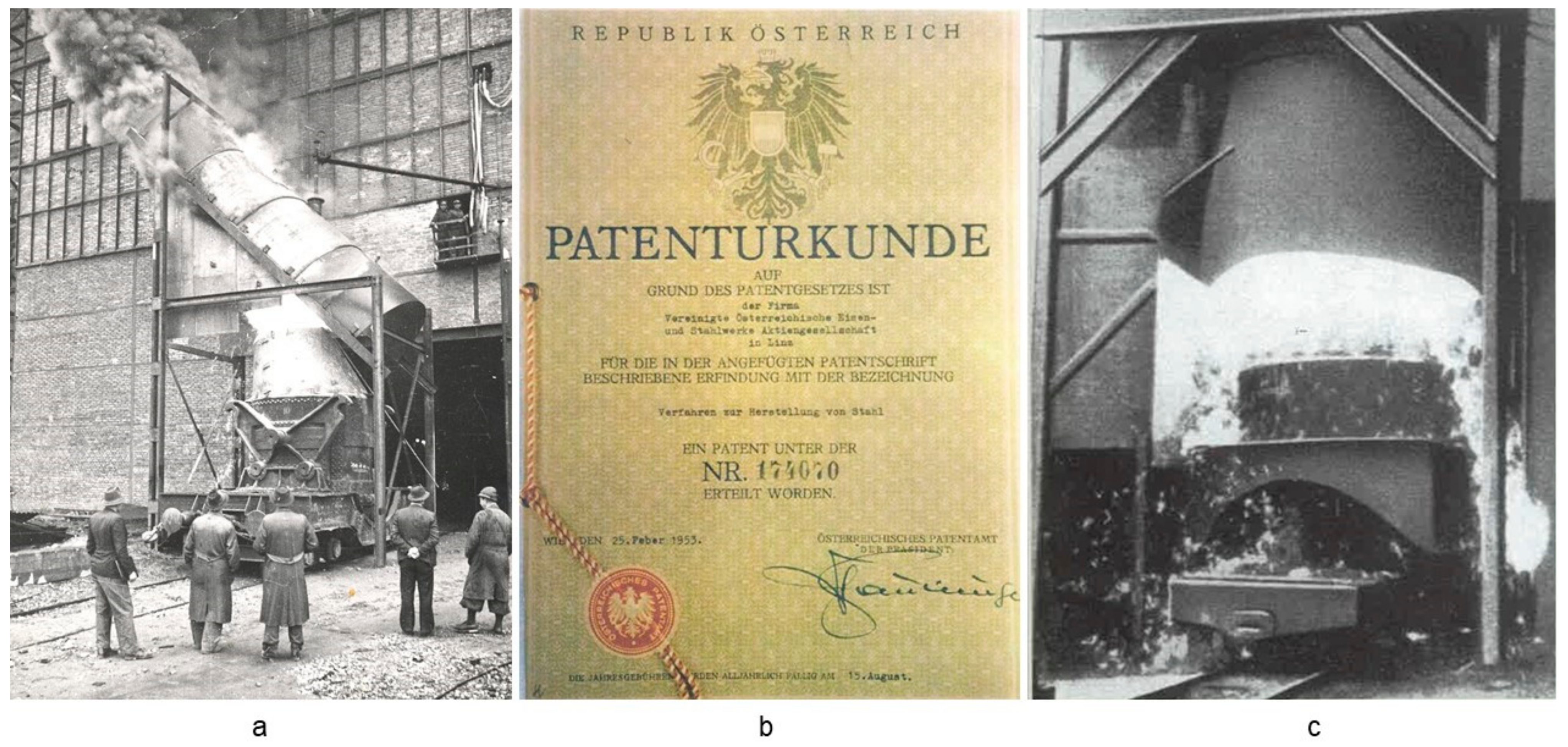
Basic Oxygen Furnace (BOF) steelmaking is, worldwide, the most frequently applied process. According to the world steel organization statistical report, 2021, it saw a total production share of 73.2%, or 1371.2 million tons per year of the world steel production in 2020. The rest is produced in Electric Arc Furnace (EAF)-based steel mills (26.3%), and only a very few open-hearth and induction furnace-based steel mills. The BOF technology remains the leading technology applied based on its undoubted advantages in productivity and liquid steel composition control. The BOF technology started as the LD process 70 years ago, with the first heat applied in November 1952 in a steel mill in Linz, Austria. The name LD was formed from the first letters of the two sites with the first industrial scale plants, Linz and Donawitz, both in Austria. The history and development of the process have been honored in multiple anniversary publications over the last few decades. Nevertheless, the focus of the steel industry worldwide is significantly changing following a social and political trend and the requirement for fossil-free energy generation and industrial production to be in accordance with the world climate targets committed to in relation to the decades leading up to 2050.

oxygen steelmaking LD-process BOF zero carbon process technology history advancements

1. How It Started

At the end of WWII, Austria was occupied by the allied forces: the USA, UK, France, and the Soviet Union. All industrial assets had been heavily damaged by air raids during the war. In 1946, the assets were returned to the newly formed Republic of Austria, and reconstruction under the framework of the Marschall Plan started at VÖEST-Linz and ÖAMG-Donawitz. In June 1947, the first blast furnace in Linz was blown-in, and steel production restarted with a repaired open-hearth furnace. In 1948 the new government launched the “Iron and Steel Plan”, which allocated the production of flat steel to Linz and the production of long products to Donawitz. The plan included starting the production of finished products in a heavy-plate mill, restored after air raids and demolition, and building a new slabbing and hot-strip mill in Linz.
In the meantime, all important players in the LD-history: T. Suess, H. Trenkler, H. Hauttmann, and H. Weitzer had arrived back in Austria from their former employments in the German steel industry [1]. From the very beginning, it was obvious that basing the future flat production in Linz on open-hearth technology was too expensive to succeed, but time was running out because the new facilities were already under construction. Based on this conclusion and knowledge about trials carried out during the war to produce steel from hot metal by oxygen refining, the team searched for other activities in this field in Europe [2].
When they heard about successful trials with oxygen purification at the von Roll steel mill in Gerlafingen, Switzerland, directed from Prof. R. Durrer, the Austrian engineers visited the plant for a technical exchange. After this visit, the decision was taken to develop the process [3].
In May 1949, a conference on oxygen metallurgy was held at the Montanuniversität, Leoben, with participants from Austria, Germany, and Switzerland. A division of tasks in developing oxygen for steel production was agreed upon between von Roll’s Gerlafingen, Mannesmann AG, VÖEST, and ÖAMG. In Gerlafingen, oxygen refining would take place in the EAF, in Huckingen, bottom injection would be carried out in the Thomas converter, in Donwitz, oxygen was used for ore reduction in a shaft furnace and for obtaining a manganese-rich slag for alloying purposes, and in Linz, the refining of hot metal with pure oxygen was to be developed [4].
Trials began in Linz on 2 June 1949. In a two-ton converter with vertical blowing of oxygen onto a hot metal melt, the breakthrough was achieved on 25 June after initial failures. Hot metal could be refined in a reproducible manner into steel with lower oxygen pressure and a greater distance of the blowing lance from the melt. The steel could be rolled without any problems, and the testing laboratory managed by H. Hauttmann judged the quality of the new steel to be excellent.
In Linz, the trials were systematically continued. In parallel, a refining station for blowing oxygen in a 15-ton vessel was built on the outer wall of the steel plant, which was commissioned with the first batch on 2 October 1949; see Figure 1 [5]. These trials subsequently clarified questions of the large-scale feasibility of the process, its economy, and the new steel’s service properties. It was possible to roll plates of excellent quality from 11-ton slab blocks [6].
Figure 1. First blowing trials with 15-ton vessel in Linz (a), LD-Patent from February 1953 (b), and blowing trials with 10-ton ladle in Donawitz (c), Reprinted with permission from Refs. [5][7][8], 2022, Voestalpine AG.

2. State-of-The-Art in Technology

The past decade has seen numerous innovations in both plant technology and process control across the entire LD-process. A graphical representation of the technological innovations implemented over the past decades is given in Figure 2. The focus was on improved plant availability and process stability, mainly driven by the increasing quality requirements for the blowing process itself. Furthermore, the requirements for the post-treatment to produce high-quality steel grades increased [9][10].
Figure 2. Overview of the technological innovations in the LD converter.

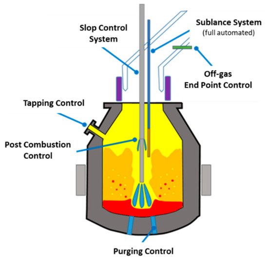
2.1. Converter Equipment

In the case of new construction or enlargement of the converter vessels themselves, models for the optimal design of the converter geometry support many plant engineers. The increase in the service life of the converter vessel shell is improved, for example, by additional cooling systems in the hat area or the trunnion ring itself (ring gap systems). High-strength steel materials with correspondingly high heat resistance are increasingly used, even if their processing and repairs are associated with significantly higher costs (temperature control) to avoid cracking. Innovative trunnion ring systems whose task is to create a secure connection between the ring and the converter vessel itself are being used and contribute to increasing the service life and operational safety. [11] Removable converter bottoms enable rapid dismantling and assembly of the vessel bottom and shell. In combination with modern brick lining machines, the relining times of a converter could be reduced [12]. The use of fast frequency-controlled tilting drives with corresponding torque for moving the high masses of vessel, refractory material, and contents goes hand in hand, whereby increasing automation requires an ever-higher accuracy of the rotation angles.

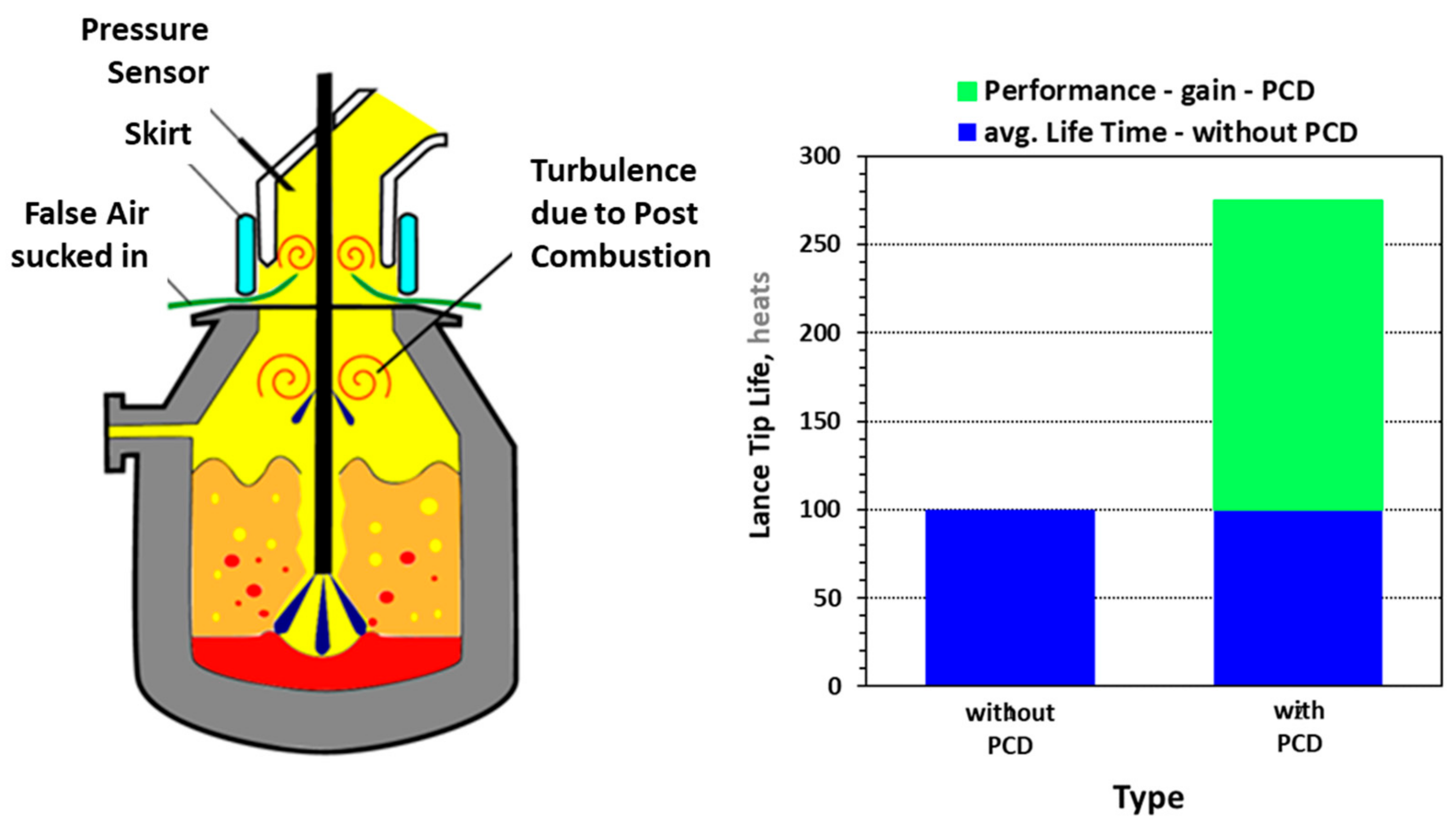
2.2. Blowing Process

The blowing lance geometry was optimized for the larger converter vessels based on sophisticated CFD models in combination with water model tests [13]. Post-combustion distributors (PCD), through which a portion of the oxygen is injected via fine ring channels along the lance, make it possible to reduce lance skulling and increase the operating time of the blast lance by post-combustion of the converter gas, Figure 3 [14][15][16].
Figure 3. Advantage of PCD-units for increased lifetime of oxygen-blowing lance and lance tips [16].
At the same time, this technique reduces the skulls in the top cone area of the converter. A separate controlled system for the post-combustion unit (dual flow post-combustion (DFPC) lance) enables additional heat to be recovered in a targeted manner. It thus allows the scrap rate to be increased, but in return reduces the amount of energy to be recovered during electricity generation. Increasing the scrap rate at the converter is currently one feasible possibility to reduce the CO2 emissions of the integrated route. In addition to the DFPC lance, lances for scrap preheating also show potential here [17].
Depending on the availability of hot metal and its chemically bound heat (carbon, silicon, manganese, and others), the hot metal ratio in the ferrous charge differs in variable proportions between 72 and 95% of hot metal. An overview of the hot metal ratio for different BOF steelmaking plants in the Americas, Europe, and Asia is presented in Figure 4. The dots marked with CSA and VASL are the extreme cases for medium-sized converter steel plants. In case of intensive hot metal use, a considerable number of additional coolants (iron ore, sinter, iron dust, other) is necessary, which can lead to an unsteady blowing behavior. The same effect occurs with very low hot metal ratios, because here the addition of heating agents (ferrosilicon, coke, other) interrupts the de-carburization during the refining. A balanced heat balance or correspondingly high reaction volume in the converter should be aimed for, if possible, to avoid slopping. For the early detection and reduction of slopping, numerous measuring systems are in operation or in test use, which predict the blowing process’s stability, based either on acoustic signals or vibration measurements [18].
Figure 4. Overview of hot metal ratio of steel producers worldwide.

2.3. Bottom-Purging

The arrangement and availability of the bottom purge, which is indispensable for achieving the lowest phosphorus content, were optimized. High purging performance with high availability up to the end of the lining campaign of up to more than 4000 melts are demanded from the purging systems. An essential specification is that wear of the purging blocks and their surrounding refractory material should coincide [13]. The use of multi-hole plug (MHP) purging blocks compared to single-hole plug (SHP) blocks is becoming increasingly common. The corresponding upgrading of the purging gas control station to supply the purging gas media argon and nitrogen in sufficient quantities is mandatory. Purging with constantly high purging rates ensures the necessary good mixing of the melt and promotes the steel/slag reaction. Separate control of the individual plugs to generate additional effective turbulence and homogenization of the steel has been suggested in some cases [19].

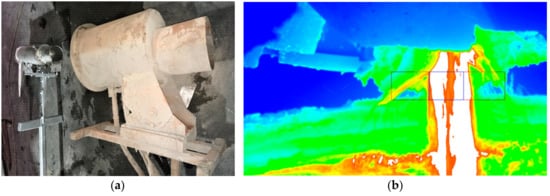
2.4. Endpoint Detection
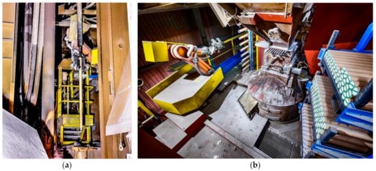
For the predetermination of the carbon content at the end of the main blowing process as well as the final blowing temperature and the determination of the final blowing point, powerful process models are used. They are combined with waste gas analysis systems using spectrometers or laser systems and sublance systems. The main advantages are an increase in efficiency in the quality fulfilment, the steel yield, and the protection of the refractory material with an overall significant cost reduction [14][20][21].
Sublance systems were innovatively adapted with robot technology to ensure availability on the one hand and to completely take over the manipulation of the large probe bodies from the employee on the other (see Figure 5). Camera systems are also combined with sophisticated system logic to control the entire manipulation and measuring process. This provides additional safety for employees by eliminating the risky steel sampling from the converter [22][23]. The endeavor regarding an on-site steel analysis without the necessary preparation of the sample to analyze the steel composition is already partly in use. For this purpose, container laboratories with fully integrated laboratory technology, including automatic manipulation with high sample throughput and analytical accuracy, are installed [24].
Figure 5. Installation of the new sublance probe manipulation system. The robot attaches the probe to the sublance (a); robot with the magazine for probe storage (b) [22].

2.5. Tapping

The primary objective during crude steel tapping from the converter is the prevention of the carry-over of the phosphorus-rich LD slag to the steel ladle. While ball and dart systems based on gravity are still used in some LD steel plants, most plants have switched to pneumatic closure devices [25]. Infrared-based camera systems have replaced electromagnetic detectors (EMLI) due to their low availability (see Figure 6). By detecting the different emission spectra of steel and slag, an almost slag-free tapping (2–3 kg slag/ton crude steel) can be achieved with pneumatic closure units (slag stopper hammer) despite harsh conditions caused by smoke and dust. New camera systems allow higher resolution, higher availability, and significantly smaller size. This leads to a considerable reduction in maintenance costs.
Figure 6. (a) Slag stopping systems with (b) infrared slag detection latest generation.
In recent years, the development of semi-automatic or automatic tapping technology has been an endeavor for steel manufacturers. The aim is to achieve a high level of system availability, with the tapping process merely being monitored by the operating personnel. The basic conditions for this are a suitable, exact control of the tilting drives as well as the necessary video equipment, including image evaluation. The positioning of the LD converter under the condition of the maximum steel bath level height above the tapping spout and the avoidance of the converter slag overflowing the converter mouth are mandatory requirements. New generation, model-supported camera systems offer a high degree of reliability in this respect, even in harsh environmental conditions [26][27].

2.6. Off-Gas Cleaning

In many LD steel plants, off-gas purification and utilization are carried out by waste heat boilers in which steam is generated by the hot converter gas (1600 °C), which is primarily utilized in the steel plant (vacuum systems, blast furnaces, hot water preparation). In the evaporative cooler, water and steam are used as atomizers to remove the coarse dust from the exhaust gas, which is then further cooled (200 °C). Fine dust is separated from the dry gas in electro dry filter systems. Sensors monitoring for optimum dust separation and avoidance of skull formation in the exhaust system have been used for years and are also used for process control. The dry, coarse, and fine dust is further processed by hot briquetting, pelletizing, or granulation. Inline zinc measurements are used to control the extraction of zinc-containing byproducts. The granules (>10% Zn, ~15 moisture content) offer higher durability, especially when transported to recycling plants. The low Zn fractions (<10%) of dry dust briquettes are used in the LD-process as additional cooling agents during the main blowing process.

References

  1. Kreulitsch, H.; Krieger, W.; Antliger, K.; Jungreithmeier, A. Der LD-Prozess ein Ökologisch Optimiertes Verfahren; Neue Hütte: Schmalkalden, Germany, 1992; Volume 37, pp. 313–320.
  2. Stein-Versen, R. 40 Jahre LD-Verfahren. Stahl Eisen 1992, 112, 72–79.
  3. Durrer, R.; Hellbrügge, H.; Richter-Brohm, H. Die Entstehung des LD-Sauerstoffaufblas-Verfahrens. Stahl Eisen 1965, 85, 1751–1754.
  4. Kalla, U.; Kreutzer, W. Entwicklungsrichtungen in der Stahlerzeugung. Stahl Eisen 1970, 90, 1146–1154.
  5. Habashi, F. Pioneers of the Steel Industry: Part 7 Oxygen in Steelmaking. Steel Times Int. Jan./Febr. 2012, 44.
  6. ASME. Oxygen Process Steelmaking Vessel; ASME Publication: New York, NY, USA, 1985.
  7. Gebert, W.; Müller, J.; Hiebler, M. Worldwide Trends and Development in LD Converter Steelmaking. In Proceedings of the IS’06–Siemens VAI’s Iron and Steelmaking Conference, Linz, Austria, 9–11 October 2006.
  8. Werk Donawitz Entwicklung und Umfeld 50 Jahre LD-Verfahren; Voestalpine Bahnsystem GmbH: Munchen, Germany, 2002.
  9. Höfer, W.; Auberger, E.; Apfolterer, R.; Exenberger, R.; Ebner, K. Converter Vessel exchange at voestalpine Stahl GmbH in Linz. In Proceedings of the EOSC Proceeding, Stockholm, Sweden, 7–9 September 2011.
  10. Zuliani, D.; Scipolo, V. iBOF® Technology Improves BOF Process Control, Endpoint Detection and Slop Mitigation. In Proceedings of the AISTech Proceeding, Pittsburgh, PA, USA, 16–19 May 2016.
  11. Torok, S.; Wimmer, G.; Unterrainer, G.; Vailancourt, D. Revamp of BOF Converters at AK Steel-Middletown Works Using Vaicon Link 2.0 Converter Vessel Suspension System. In Proceedings of the AISTech Proceeding, Cleveland, OH, USA, 31 August–2 September 2020.
  12. Demuner, L.; Voraberger, B.; Correa, W.; Wimmer, G. Increased Safety and Performance of BOF Relining at Ternium Brasil. In Proceedings of the AISTech Proceeding, Nashville, TN, USA, 29 June–1 July 2021.
  13. Wimmer, E.; Schwaha, R.; Wimmer, G. Optimization of Converter Design with CFD—Practical application for converter Revamps. In Proceedings of the ESTAD proceeding, Paris, France, 26–29 June 2017.
  14. Külchen, R.; Metzul, A.; Bläser, M. In-situ Laser Gas Measurement at the Converter. In Proceedings of the EOSC Proceeding, Trinec, Czech Republic, 9–11 September 2014.
  15. Panhofer, H.; Egger, M.W.; Strelbisky, M. First Operating Experiences with Post-Combustion Lances at BOF shop LD3. In Proceedings of the ESTAD Proceeding, Dusseldorf, Germany, 15–19 June 2015.
  16. Lehner, J.; Egger, M.W.; Panhofer, H.; Strelbisky, M. First Operating Experiences with Post-Combustion Lances at BOF shop LD3. In Proceedings of the ESTAD Proceeding, Vienna, Austria, 26–29 June 2017.
  17. Wimmer, G.; Ke, J.W.; Dimitrov, S.; Voraberger, B. Increase of Scrap Rate in Converter Steelmaking; CSST: Tianjin, China, 2018.
  18. Vazquez, A.; Scipolo, V.; Zuliani, D. Effective Detection of Slopping Events for Improved BOF Performance and Reduction of GHG Emissions. In Proceedings of the EOSC Proceeding, Trinec, Czech Republic, 9–11 September 2014.
  19. Odenthal, H.-J.; Grygorov, P.; Refferscheid, M.; Schlüter, J. Advanced Blowing and Stirring Conditions in the BOF Process. In Proceedings of the AISTech Proceeding, Pittsburg, PA, USA, 6–9 May 2013; pp. 897–909.
  20. Hubmer, R.; Hofinger, S.; Hiebler, M.; Kühböck, H. Latest Generation of Automation Solutions for BOF Converters. In Proceedings of the EOSC Proceeding, Trinec, Czech Republic, 9–11 September 2014.
  21. Carvalho, D. BOF Process Optimization and Technology Improvements at Ternium Brazil. In Proceedings of the AISTech Proceeding, Pittsburgh, PA, USA, 6–9 May 2019.
  22. Egger, M.W.; Priesner, A.; Lehner, J.; Nogratnig, H.; Lechner, H.; Wimmer, G. Successful revamp of sublance manipulators for the LD converters at voestalpine Stahl GmbH: Operational experience gained in the first year. In Proceedings of the AISTech Proceeding, Pittsburgh, PA, USA, 16–19 May 2016.
  23. Gerstorfer, G.; Keplinger, T.; Priesner, A.; Sedivy, C.; Traxinger, H.; Vorarberger, B.; Watzinger, S. Robotic applications continuously enhancing safety in melt shops. In Proceedings of the EOSC Proceeding, Taranto, Italy, 10–12 October 2018.
  24. Cuypers, J.; Vergauwnes, M.; Beyens, D.; Maenhoudt, M. QuiK-Spec Multi-Lance Probe for inblow and endblow application: Your critical link to a fast converter sample analysis. In Proceedings of the AISTech Proceeding, Pittsburgh, PA, USA, 6–9 May 2019.
  25. Serrano, E.; Wimmer, G.; Runner, D.; Li, Y.; Vaillancourt, D.; Maringer, M. Installation of Vaicon Slag Stopper at U.S. Steel—Great Lakes Works. In Proceedings of the AISTech Proceeding, Cleveland, OH, USA, 31 August–2 September 2020.
  26. Thomasberger, J.; Premanand, K.; Kuczora, R.; Linden, W. Experience on Automatic BOF Tapping in a European Steel Plant. In Proceedings of the EOSC Proceeding, Taranto, Italy, 10–12 October 2018.
  27. Linden, W.; Reichel, J. Automatic Tapping at BOF Converters. In Proceedings of the EOSC Proceeding, Trinec, Czech Republic, 9–11 September 2014.
More
Information
Contributors MDPI registered users' name will be linked to their SciProfiles pages. To register with us, please refer to https://encyclopedia.pub/register : , ,
View Times: 2.6K
Revisions: 2 times (View History)
Update Date: 09 Jun 2022
1000/1000