Your browser does not fully support modern features. Please upgrade for a smoother experience.
Submitted Successfully!
 +1 credit
Thank you for your contribution! You can also upload a video entry or images related to this topic.
For video creation, please contact our Academic Video Service.
| Version | Summary | Created by | Modification | Content Size | Created at | Operation |
|---|---|---|---|---|---|---|
| 1 | Eladio Durán Aranda | -- | 3640 | 2022-04-27 11:42:54 | | | |
| 2 | Rita Xu | Meta information modification | 3640 | 2022-04-27 11:59:23 | | |
Video Upload Options
We provide professional Academic Video Service to translate complex research into visually appealing presentations. Would you like to try it?
Cite
If you have any further questions, please contact Encyclopedia Editorial Office.
Durán Aranda, E.; Litrán, S.P.; Semião, J.F.L.C.; Diaz, C. Multiple-Output DC–DC Converters. Encyclopedia. Available online: https://encyclopedia.pub/entry/22366 (accessed on 17 July 2026).
Durán Aranda E, Litrán SP, Semião JFLC, Diaz C. Multiple-Output DC–DC Converters. Encyclopedia. Available at: https://encyclopedia.pub/entry/22366. Accessed July 17, 2026.
Durán Aranda, Eladio, Salvador Pérez Litrán, Jorge Filipe Leal Costa Semião, Cristian Diaz. "Multiple-Output DC–DC Converters" Encyclopedia, https://encyclopedia.pub/entry/22366 (accessed July 17, 2026).
Durán Aranda, E., Litrán, S.P., Semião, J.F.L.C., & Diaz, C. (2022, April 27). Multiple-Output DC–DC Converters. In Encyclopedia. https://encyclopedia.pub/entry/22366
Durán Aranda, Eladio, et al. "Multiple-Output DC–DC Converters." Encyclopedia. Web. 27 April, 2022.
Copy Citation
Multiple-output DC–DC converters are essential in a multitude of applications where different DC output voltages are required. The interest and importance of this type of multiport configuration is also reflected in that many electronics manufacturers currently develop integrated solutions. Traditionally, the different output voltages required are obtained by means of a transformer with several windings, which are in addition to providing electrical isolation. However, the current trend in the development of multiple-output DC–DC converters follows general aspects, such as low losses, high-power density, and high efficiency, as well as the development of new architectures and control strategies.
DC–DC converters
multiple outputs
applications
1. Introduction
Multiple-output DC–DC converters are fundamental in electric power supply, distribution, management, and power delivery systems. They are essential in applications such as: Intermediate Bus Architecture (IBA), Distributed Power Architectures (DPA), Dynamic Bus Architecture (DBA), Central Control Architecture (CCA), Datacom and Telecom, Light-Emitting Diodes (LEDs), consumer electronics products, battery chargers, or even Electric Vehicles (EV). These converters are used for USB power delivery, I/O, CPUs, FPGAs, ASICs, and other low-voltage devices, applications where controllability, efficiency, reliability, and miniaturization are critical.
Undoubtedly, the development of power switch semiconductor technologies has also contributed significantly to more efficient switching and has facilitated a higher frequency operation. This has allowed the development of applications where multiple-output DC–DC converters are used, considering mainly three aspects: high-power density, high efficiency, and small size. The increase in the rating of power devices, such as Insulated Gate Bipolar Transistors (IGBT) and Metal-Oxide-Semiconductor Field-Effect Transistor (MOSFET) technologies, has allowed innumerable applications to be addressed in the last 40 years. They have helped to improve energy efficiency and CO2 reductions, in commercial, residential, transportation systems, industrial, military, aerospace, computer systems, lighting, and vehicle applications. MOSFET and IGBT, either as power modules or within discrete devices, have been the preferred technologies for high and medium power applications. IGBTs are used in applications of high-current, with voltages over 1 kV and up to 10 kVA, while MOSFETs are used in applications below 1 kV, but they are the most suitable in applications of high switching frequency, between 10–100 kHz.
Although silicon-based technologies have improved enormously in the recent years, and still continue to improve, this development will be restricted, ultimately, by silicon technology limitations [1]. Among the semiconductor materials with the greatest future potential are those with a Wide Band Gap (WBG), particularly Gallium Nitride (GaN) and Silicon Carbide (SiC). The physical properties of WBG materials make them especially suitable for high switching frequency and high-power applications, also giving them high resistance to high temperatures, lower switching losses, with low reverse recovery and low on-resistance, a better relationship between breakdown voltage (VBD) and on-resistance (RDS(ON)), lower cooling requirements, and with low parasitic inductance. Applications where broadband technology is experiencing a considerable growth are: in the lighting sector (using GaN based LEDs); in the generation (transmission and distribution of electrical energy, where SiC devices present significant improvements in energy efficiency of the electrical network); and hybrid and fully electric vehicles (where GaN and SiC-based devices are essential elements, both in the propulsion and energy distribution systems of the vehicle).
The interest in DC–DC converters with multiple outputs is reflected in the sub-cited analysis and numerous publications, both from the academic, research, and economic/business world [2][3][4][5][6][7][8][9][10][11], as well as from industry and manufacturer publications [12][13][14][15][16][17]. The most recent forecasts estimate that the market for DC–DC converters is expected to increase at a CAGR (Compound Annual Growth Rate) of 12.1% in the next five years, from $9.9 billion in 2021 to $17.6 billion in 2026, and that the market for industrial power supply is expected to increase at a CAGR of 6.9% in the same period, from $7.0 billion in 2021 to $9.7 billion in 2026, with multiple-output DC–DC converters being one of the segments with the highest growth rate during the same period [18][19][20][21][22][23][24][25][26][27][28][29][30]. This growth is due to very different sectors and applications, such as storage and servers, battery management, healthcare and medical equipment, railway traction, beverage and food, information technology and telecom, transportation, consumer electronics, energy and utilities, defense and aerospace, machine tools, and security systems. Mobile Phone Industry and Internet of Things (IoT) are applications where DC–DC converters help to extend battery life. Also, the lighting sector through technology Light-Emitting Diode (LED) and Organic LED (OLED), which has provided more reliable and efficient light sources, is also an important sector. Moreover, the demand for DC–DC converters with multiple outputs in the automotive industry is driven by electric vehicles, such as Fuel Cell Electric Vehicle (FCEV), Battery Electric Vehicles (BEV), Plug-in Hybrid Vehicles (PHEV), and Hybrid Electric Vehicle (HEV).
All these applications contemplate various aspects and types of DC–DC converters, such as output number (dual-output, bipolar output, three- and four-output-type converters), power (<1 kW, 1–10 kW, 10–20 kW, and >20 kW) including low, medium, and high power, input voltage (<40 V, 40–70 V, and >70 V), output voltage (24 V, 15 V, 12 V, 5 V, and 3.3 V), isolated (one switch, two switches, and four switches converters) and non-isolated (one switch or several switches) DC–DC converters. In low-power applications, the two main trends are related to high-power density and low voltage, while in high power, with high efficiency and reliability. But the main trend is related to miniaturization for integration. Small size and weight, together with high-power density are very important items in power supplies for small format applications, mobile electronic systems, and onboard systems, driven by applications with facilities with space restrictions such as More-Electric Aircraft (MEA), Electric Vehicle (EV), Robotics, Electric Ship (ES), Robotics, Solid-State Lighting, Integrated DC–DC Power Supply and Monolithic Power Systems, Intelligent DC–DC Power Distribution (micro or nano grids), On-chip Power Supply, Wireless Remote Sensing Node and Power Transfer, New Transport Technologies, Energy Harvesting, and IoT. In these applications, multiple or single power systems are used, which distribute energy to different loads, with converters operating in power ranging from hundreds of kilowatts to a few watts. This focus on multiple-output DC–DC converter applications has also led to the development and commercialization of integrated solutions by many electronic manufacturers [31][32][33][34][35][36][37][38][39][40][41][42], and to different tutorials, webinars, on-line publications, white papers and some surveys, reviews, and overviews papers being reported in the literature.
2. Multiple-Output DC–DC Converters: Topologies and Configurations
The main objective of DC–DC power conversion is to transfer electric power from a DC source into another DC source, which can be a load, with the highest efficiency and therefore lowest losses. The DC–DC converters are widely used at all power levels (from mW to kW), current levels (from nA to hundreds of amps) and voltage levels (from mV to kV) and have been very popular for the last three decades, they can invert the polarity of the DC voltage and increase or decrease its magnitude. The topologies and properties of DC–DC converters are reported in the literature and are well known. Topology describes how source, load, inductive and capacitive elements, and switches are interconnected in the converter, while the configuration establishes the DC conversion relation between the input and output current/voltage and according to the operating mode and the converter topology. Efficiency depends on how close converter elements are to ideal condition; assuming that the same elements are available, efficiency is related to the converter topology. Switch electrical stress (current and voltage) decides the choice of semiconductor devices used to implement the switches. For lower losses on parasitic resistances, lower generated noise, and more efficient filtering, it is preferred that input and output waveforms be continuous (ideally, DC only). Complexity of a converter is measured by the number of inductors, capacitors, and switches. Efficiency and density (watts/volume) have long been the metrics used to compare the performance of power converters.
DC–DC converters can be classified depending on the number of inputs as Multiple-Input and Single-Output (MISO), or Single-Input and Single-Output (SISO), depending on the number of outputs as Single-Input and Multiple-Output (SIMO), or Multiple-Input and Multiple-Output (MIMO). In all cases, they can provide one or more output voltages, from one or more input voltages. Multiple-output DC–DC converters are of interest in applications that require several outputs, from one or more input voltages, which include configurations MIMO [43][44][45][46] and SIMO [47][48][49][50][51].
As it is showed in Figure 1, SIMO DC–DC converters can be classified into isolated and non-isolated, depending on whether they are implemented with or without an electrical isolation, by means of a transformer, generally operated at high frequency. The output/input power range is often used as the main aspect when selecting a topology. However, there are many other factors that influence the topology selection for an isolated multi-output DC–DC power converter, such as: electrical stress, size, cost, input voltage range, and output noise. The size of an isolated multi-output power converter mainly depends on the transformer size and the number of active switches employed, while for a non-isolated converter depends on the number of active switches employed. The utilization of the power transformer affects the size of the power converter. A high-frequency transformer provides galvanic isolation between input and output, and allows increasing the step-up conversion ratio, while coupled inductors can also be used to increase the step-up ratio in a DC conversion and provide different output voltages from several secondary windings.
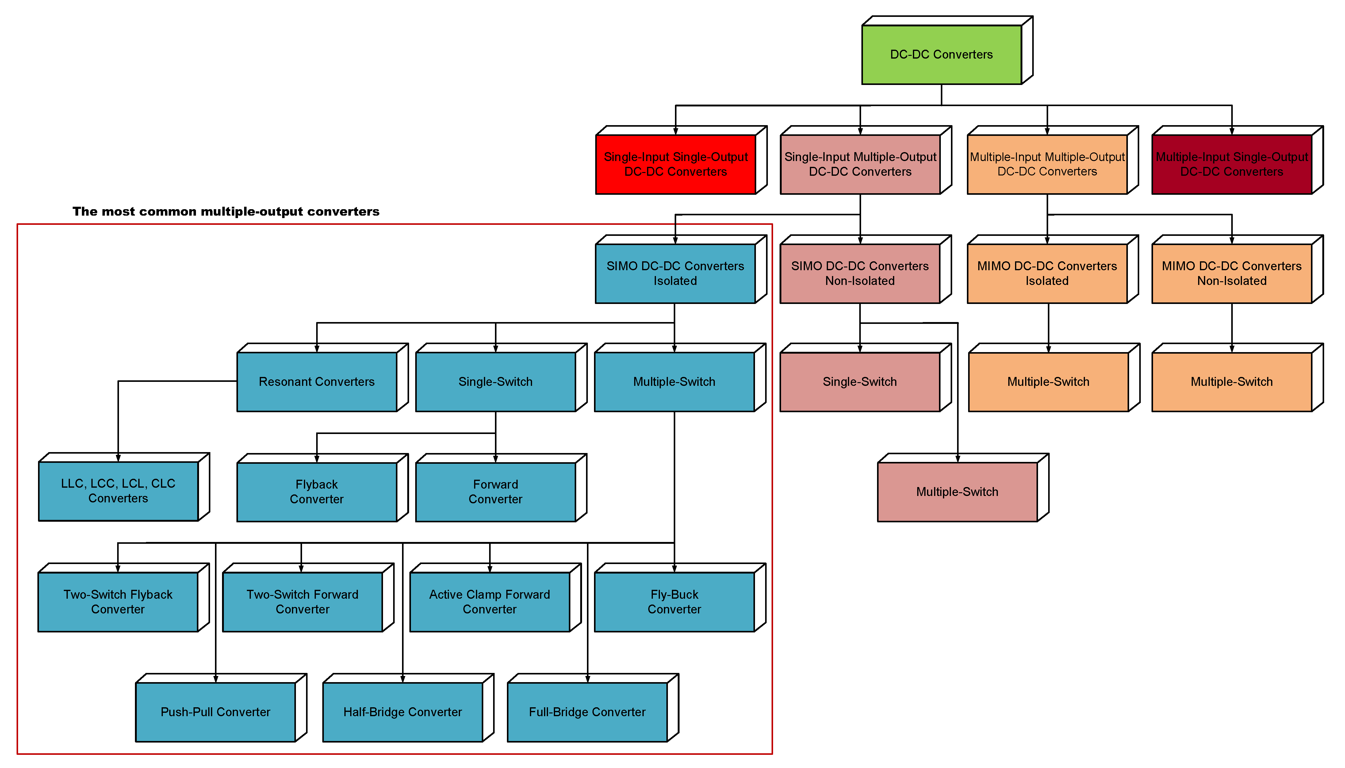
Figure 1. Multiple-Output DC–DC Converters Classification.
Control over DC conversion relation can be obtained by PWM (Pulse-Width Modulation) technique, usually using a Constant Frequency (CF). D (Duty Cycle) is the ratio between TON (Conduction Time) of switch/es and TS (Switching Period). In PWM, the output voltage regulation is corrected (adjusted) by changing the TON of the switching element in the converter. Other control strategies used in DC–DC converters are: Variable Frequency and Constant on-Time (VF-C-on-T), Variable Frequency and Constant off-Time (VF-C-off-T), and variable frequency and variable pulse width. In VF-C-on-T, the operating frequency varies as a function of the input and load current. In VF-C-off-T conduction, the operating frequency varies (implying variable on-time conduction) as a function of the input and load current. CF is usually preferred over VF control since filtering components can be optimized to suppress voltage and current ripples at switching frequency and its harmonics. Also, noise generated by VF converters is more difficult to handle, and, in some applications, it cannot be tolerated. There is a wide variety of modes, techniques (linear and nonlinear), and types of controllers used for DC–DC converters: Voltage Mode Control (VMC), Current Mode Control (CMC), Sliding Mode (SM) or Hysteretic Mode (HM), and Band-Band Control (BBC), and controllers such as PID (Proportional-Integral-Derivative), Fuzzy Logic (FL), and Neural Network (NN) in different variants and their advantages and disadvantages are well understood and described in the literature.
When several outputs must be regulated it appears a mutual Cross Regulation (CR) effect, and this is one of the critical challenges in multi-output converters, when there is a load change in any one or more of its outputs. Among the different techniques implemented to regulate multiple DC outputs, cross regulation technique is very used by its simplicity. In this technique, one of the output voltages is directly sensed by the controller and regulated to the desired value. The other output voltages are indirectly regulated (quasi-regulated) by the main inductor and switch. Of course, the non-controlled outputs have lower regulation capacity and can present a variation with respect to their nominal values (CR = △Voi/△Ioj). On the other hand, cross regulation allows the reduction in size, weight, and cost, and circuitry simplicity in several applications since it shows many advantages in terms of flexibility and integration in power-management systems. To suppress cross regulation, some methods have been reported in the literature [52][53].
2.1. SIMO DC–DC Converters Isolated
Isolated SIMO DC–DC converter topologies can be denominated as either double-ended or single-ended, based on the use of the magnetization curve (B-H curve, flux density versus magnetic field strength), as shown in Figure 2. During the operation, if the flux oscillates in two quadrants of the B-H curve (Figure 2a), then the topology is called as double-ended. While, if the flux oscillates in only one quadrant of the B-H curve (Figure 2b), then the topology is called as single-ended. In general, for given operating conditions, a single-ended topology requires a greater core than a double-ended topology and needs an additional reset winding.
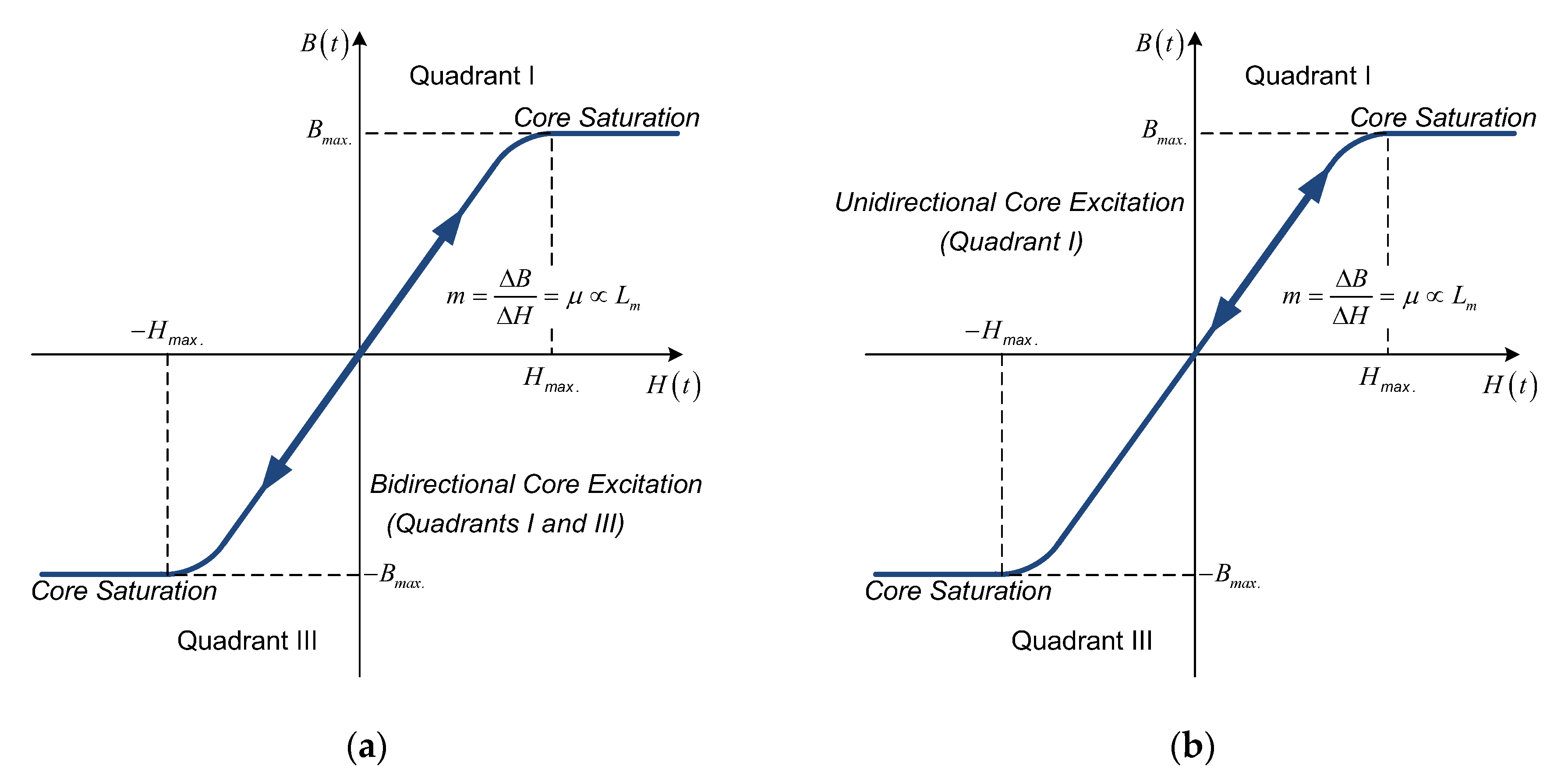
Figure 2. B-H Curve (without hysteresis) of Transformer Core. (a) Bidirectional Core Excitation. (b) Unidirectional Core Excitation.
Among Buck and Buck–Boost derived DC–DC converters, the most popular single-switch are Forward and Flyback converter, while those employing multiple switches include Full-Bridge, Half-Bridge, and Push–Pull converter. Figure 3, Figure 4 and Figure 5, show the basic isolated SIMO DC–DC converters. The output filter inductor in Full-Bridge, Half-Bridge, and Push–Pull converters acts as the inductance in a Buck converter, and thus the equation for critical inductance for the Buck is valid for these Buck-Derived converters, as long as the appropriate transformation of the input voltage due to the transformer turns ratio and topology is applied. As a result, Isolated Buck (Fly-Buck) converter is used in applications below 15 W, Flyback, and Buck-Derived converters in 10–100 W, Forward in 50–300 W, Half-Bridge, and Push–Pull converters in more than 500 W, while Full-Bridge is used in applications with a power range of 1 to 5 kW.
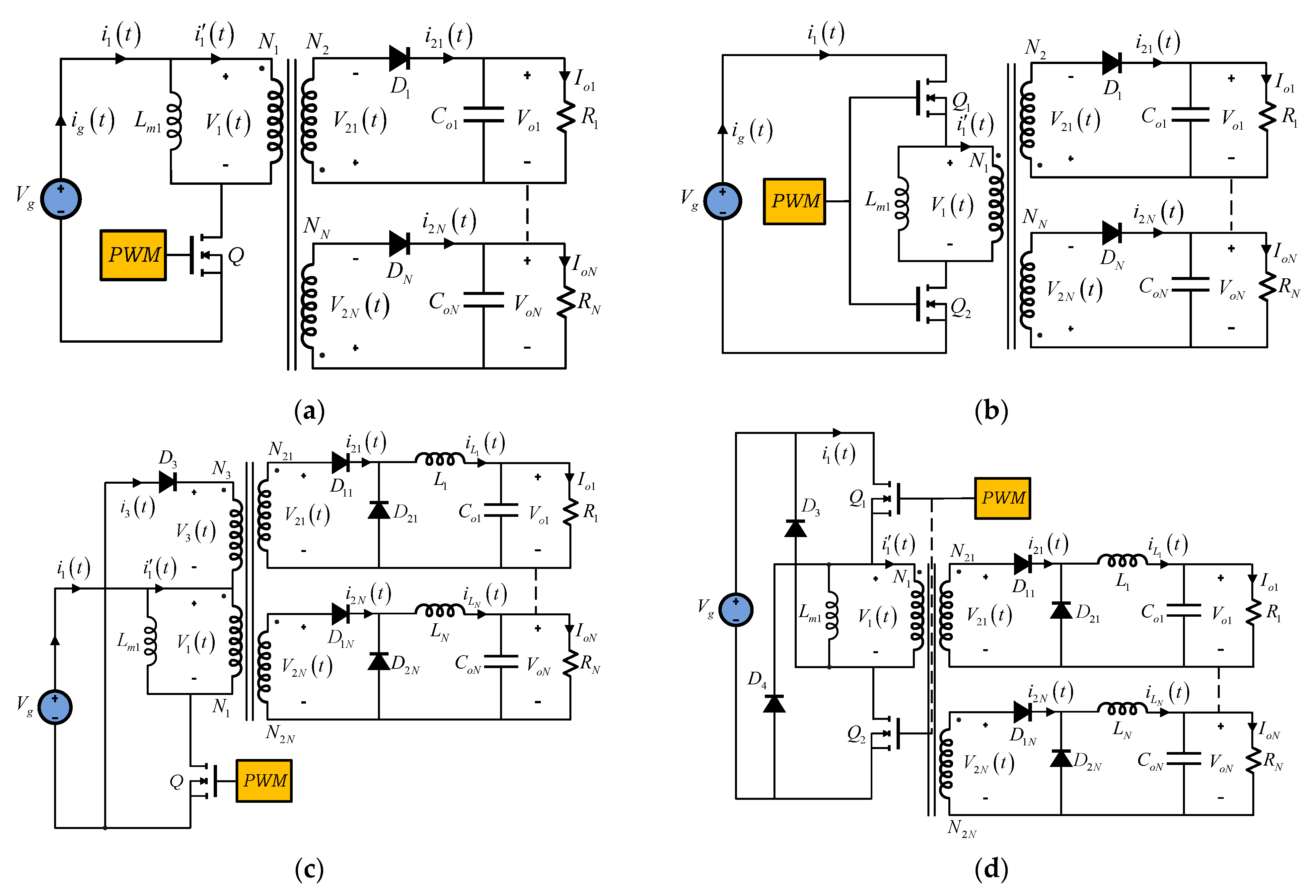
Figure 3. Multiple-Output Isolated DC–DC Converters Topologies. (a) Single-Switch Flyback Converter. (b) Two-Switch Flyback Converter. (c) Single-Switch Forward Converter. (d) Two-Switch Forward Converter.
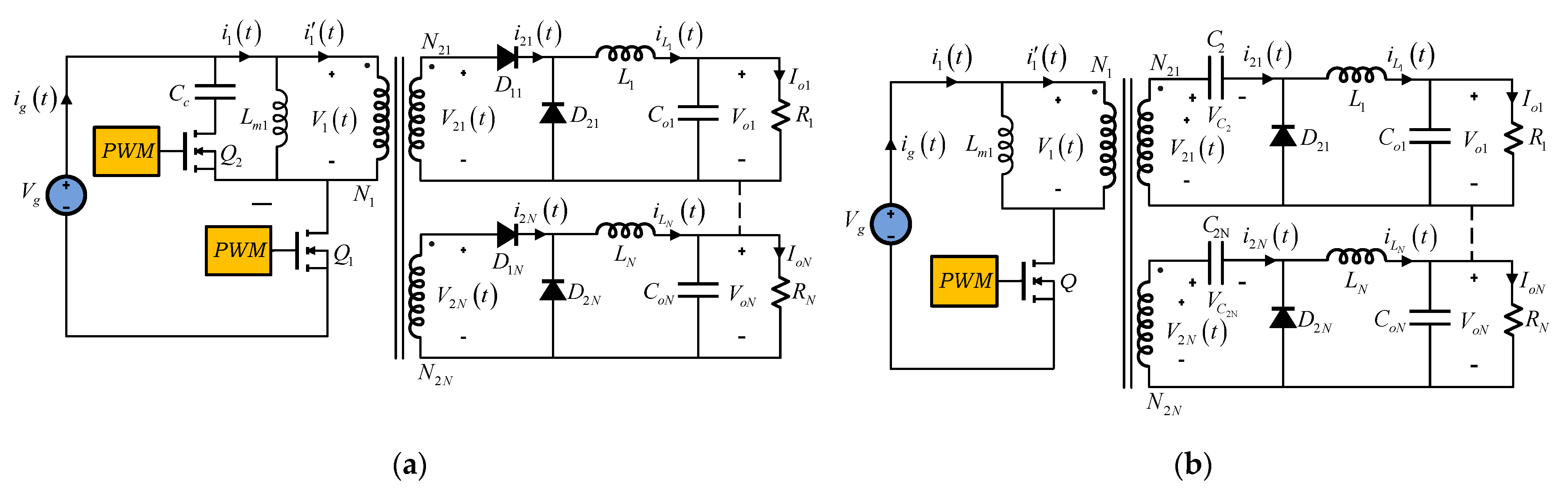
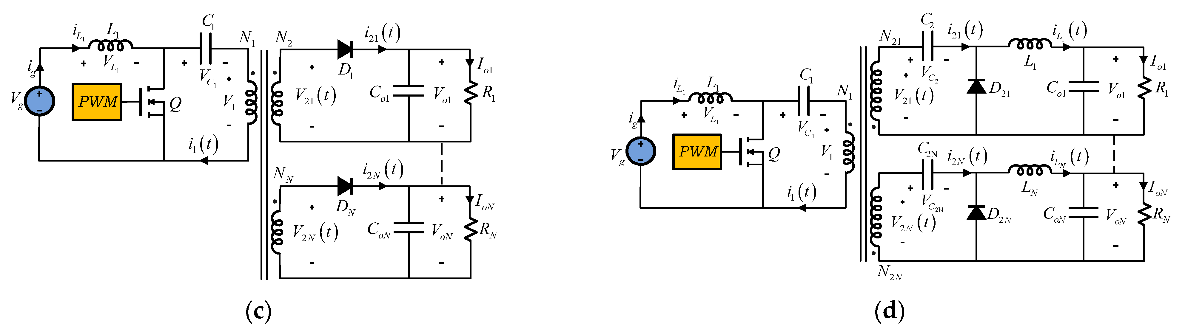
Figure 4. Multiple-Output Isolated DC–DC Converters Topologies. (a) Active Clamp Forward Converter. (b) Isolated Zeta Converter. (c) Isolated SEPIC Converter. (d) Isolated Ćuk Converter.
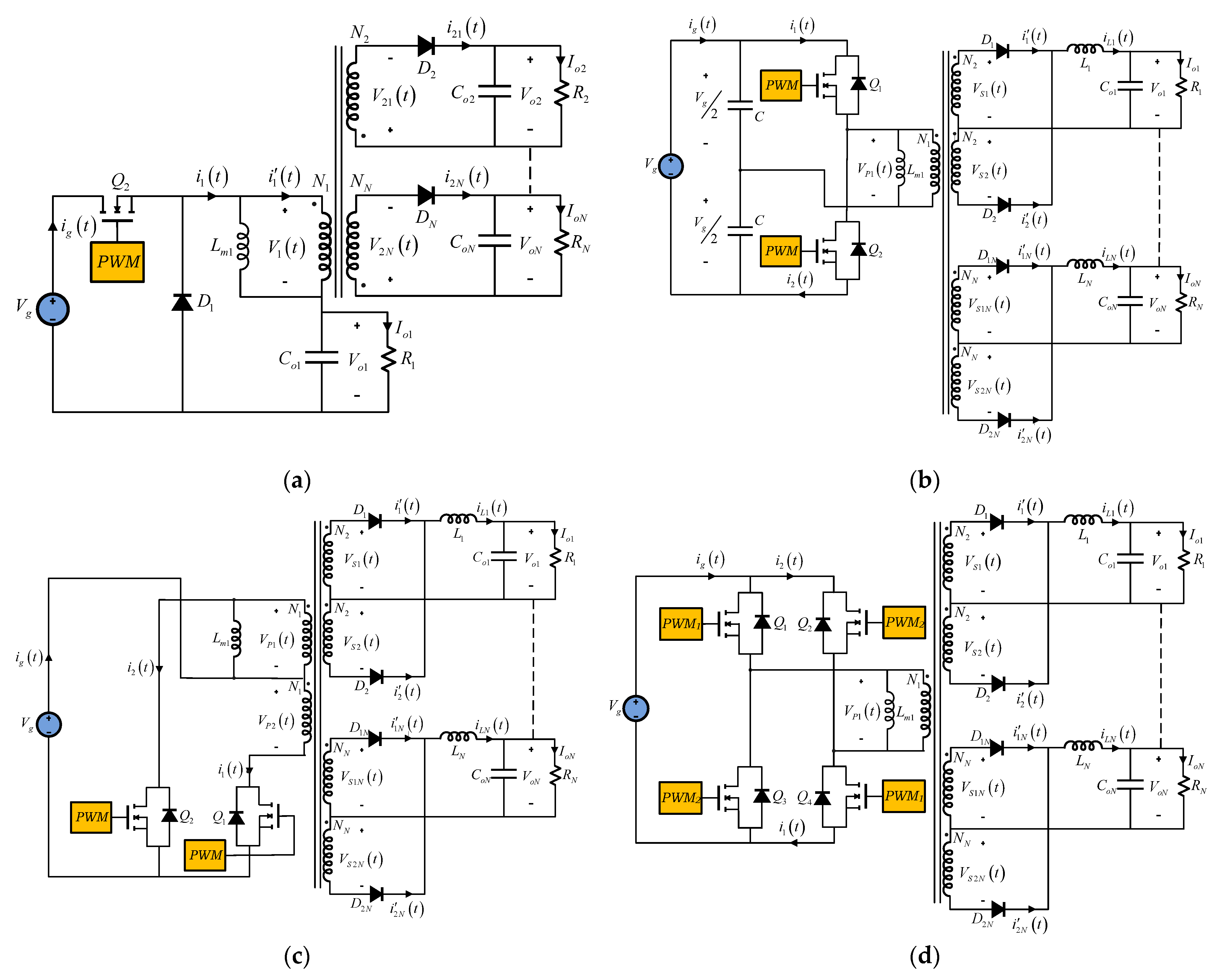
Figure 5. Multiple-Output Isolated DC–DC Converters Topologies. (a) Isolated Buck (Fly-Buck) Converter. (b) Half-Bridge Converter. (c) Push–Pull Converter. (d) Full-Bridge Converter.
Other classification of isolated multiple-output DC–DC converters can be realized depending on the switching technique: hard-switching (PWM converters) and soft-switching (resonant converters) [54][55][56]. They are traditionally used in applications such as very high frequency power supplies, induction heating, ballasts for fluorescent lamps, sonar transmitters, ultrasonic generators, and power supplies for laser cutting machines. Isolated resonant converters can be defined as converter networks to which resonant (L and C) elements are added. In contrast to square wave switch waveforms in PWM converters, resonant topologies exhibit smooth quasi-sinusoidal waveforms and, therefore, reduced switching losses. The incentive to increase the frequency at which DC–DC converters are operated is motivated by the fact that correspondingly smaller values and, hence, weights and sizes of energy storage components should result in lighter and smaller converters. However, the inevitable increase in power losses due to switching establishes a practical upper limit in the frequency range. Resonant isolated converter topologies overcome some of the switching loss mechanisms attributed to PWM converters and offer the possibility of extending the usable frequency range toward higher frequencies (typically 100 to 500 kHz). In contrast to sharp transitions in current and voltage waveforms of PWM converters, the resonant converters operate with smooth, quasi-sinusoidal, resonant waveforms, leading to reduced losses ascribed to switching transitions. Soft-switching converters can exhibit reduced switching loss, at the expense of increased conduction loss.
Resonant converters use resonant L-C elements that cause sinusoidal variation of voltage and current waveforms in order to reduce switching losses. They were developed as an alternative to simple rectangular switching, the power devices switch at high frequency, maintaining acceptable converter efficiency by minimizing the significant switching losses associated with hard-switching. In these converters, the size and weight are reduced (mainly, magnetic and filtering components) and the power density is increased, with low stress on the switching devices. In addition, the soft-switching technique utilizes Variable Frequency (VF) for regulation, with constant on-time or constant off-time, which creates an oscillating circuit that allows power device transitions to occur at zero voltage (Zero Voltage Switching, ZVS) or zero current (Zero Current Switching, ZCS), eliminating or reducing the switching losses in the converter, higher-frequency operation and reducing the size of magnetic and filter components. Both resonant techniques are widely used in many applications.
In isolated multiple-output DC–DC converters, the resonant components can be placed either on the primary or on the secondary side. When a resonant capacitor is placed on in some winding, the leakage inductance and magnetizing inductance of the transformer can be used as a resonant element in order to reduce the number of discrete magnetic components and, therefore, increase the power density of the converter.
Although there is a wide variety of isolated multiple-output resonant converter topologies, the most widely used are those based on three reactive elements, being LLC and LCC, shown in Figure 6, the most popular.
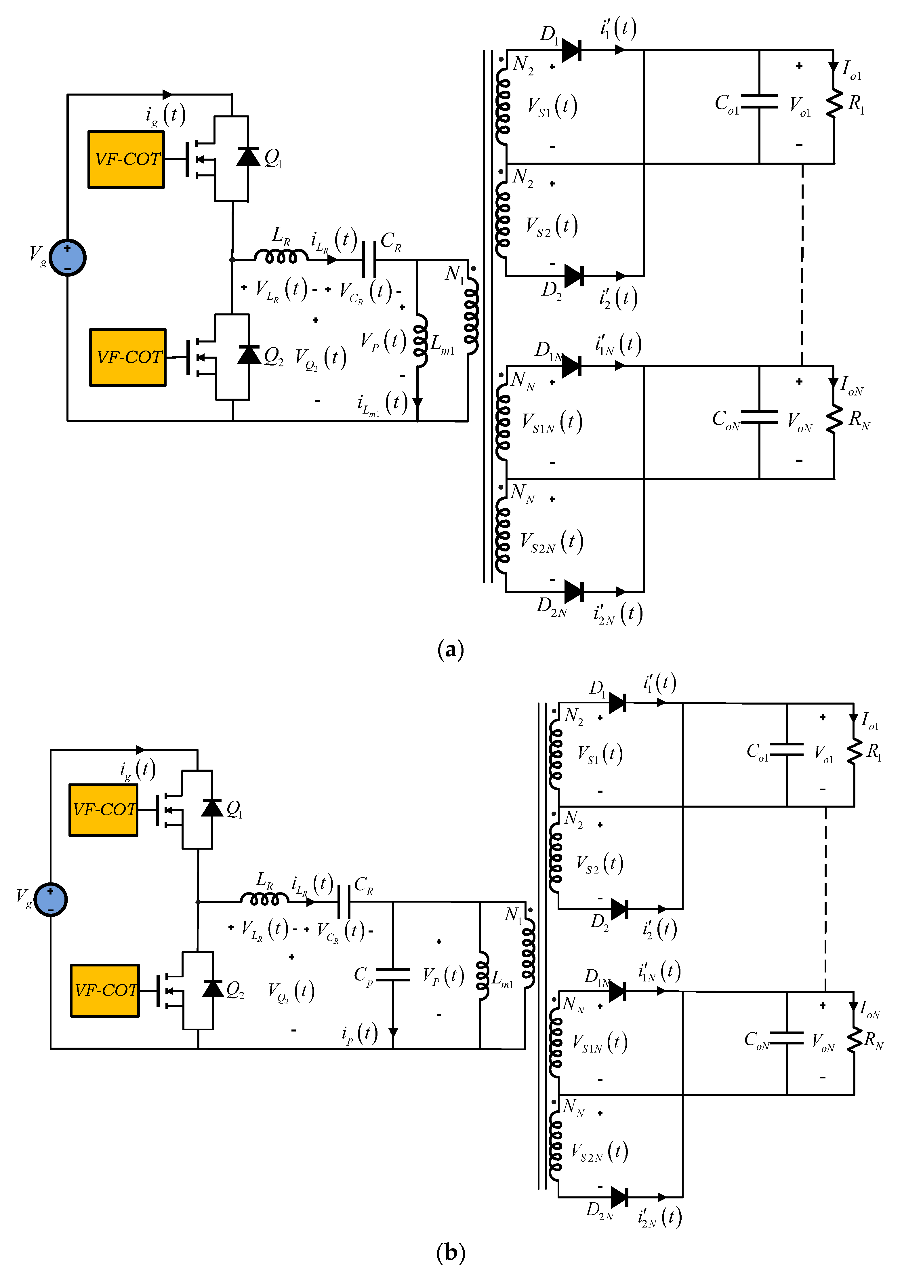
Figure 6. Three-element Multiple-Output Isolated Resonant DC–DC Converters: LLC and LCC. (a) LLC Resonant DC–DC Converter. (b) LCC Resonant DC–DC Converter.
2.2. SIMO DC–DC Converters Non-Isolated
Multiple-output converters without transformers are an alternative in applications where galvanic isolation is not required. In this sense, non-isolated multiple-output converters can be implemented with single switch or multiple switches, with their advantages and disadvantages. As an example, multiple switches require several control switches, which increases the cost, losses, and number of gate drivers in the converter, while single-switch converters cause higher stress in terms of voltage and current.
SIMO non-isolated with multiple switches converters have been developed for many applications and in different configurations and topologies [57][58][59][60][61][62][63][64]. They can provide space savings, while maintaining high efficiency. They are generally based on traditional Single-Input Single-Output (SISO) structures such as Buck, Boost, Buck–Boost and cascade Buck–Boost, as shown in Figure 7. Each output voltage is a function of a fraction of the duty cycle of the switch to which it is connected. By having several switches, different switching strategies (time sequencing [65] and time-multiplexing [66]) and operation modes (CCM and DCM) are applicable.
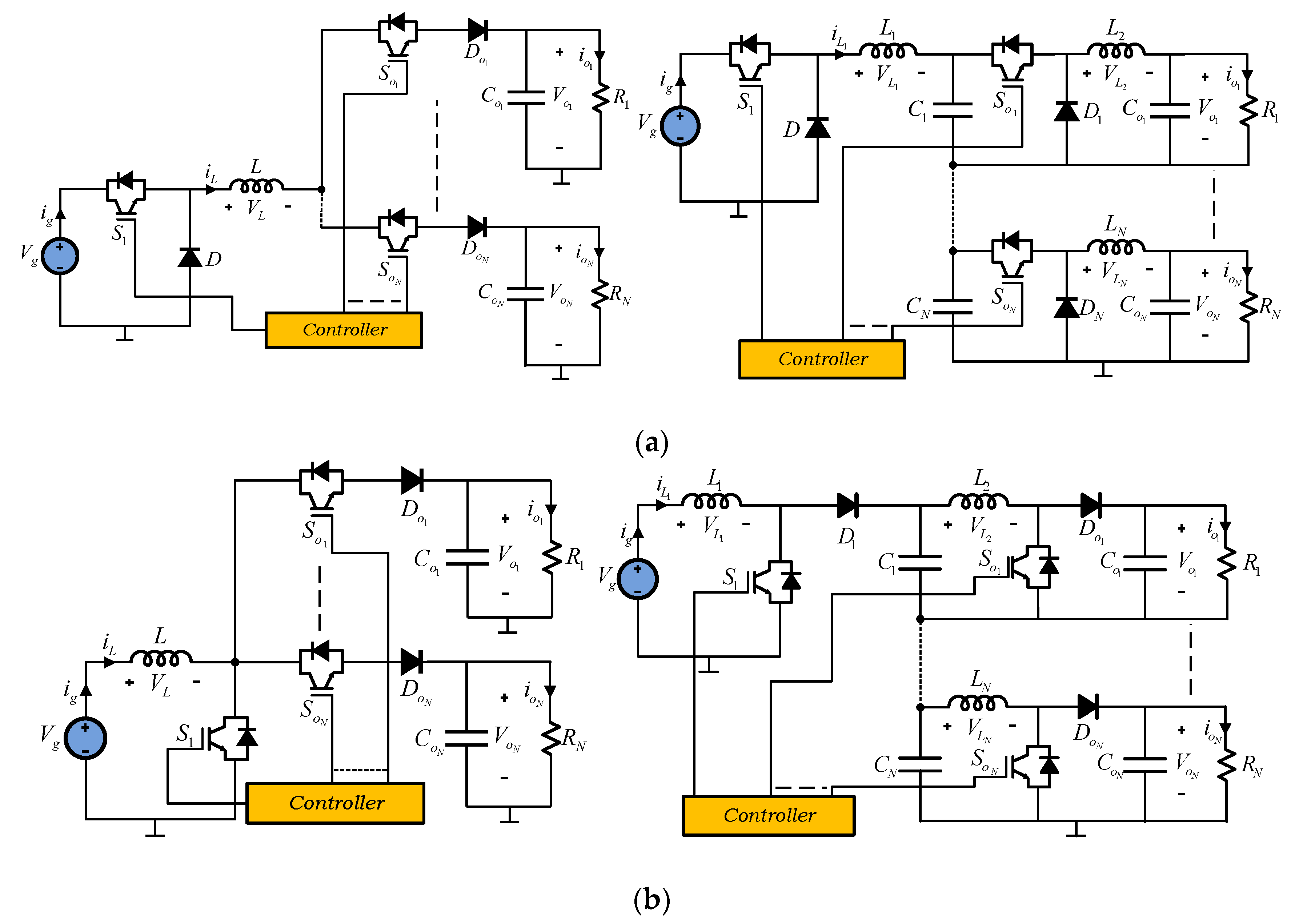
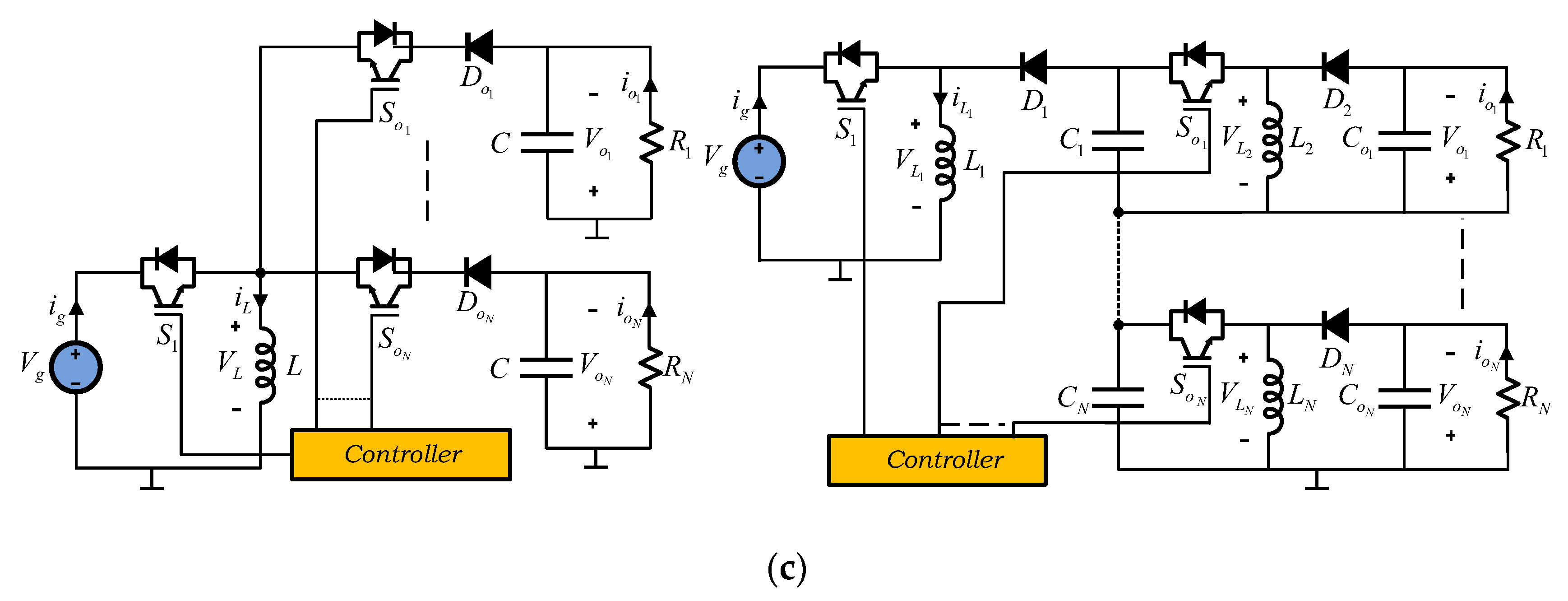
Figure 7. Single Input Multiple-Output (SIMO) non-isolated multiple switches DC–DC converters. (a) SIMO Buck Converter versions [57]. (b) SIMO Boost Converter versions. (c) SIMO Buck–Boost Converter versions.
Within SIMO non-isolated with multiple-switch converters, special attention should be paid to Single Input Dual Output (SIDO), Symmetric Outputs DC–DC Converters or Bipolar Output DC–DC Converters, as shown in Figure 8. Not only because of the interest of its applications, but also because of the different topologies that have been developed [67][68][69][70][71][72][73][74][75][76][77].
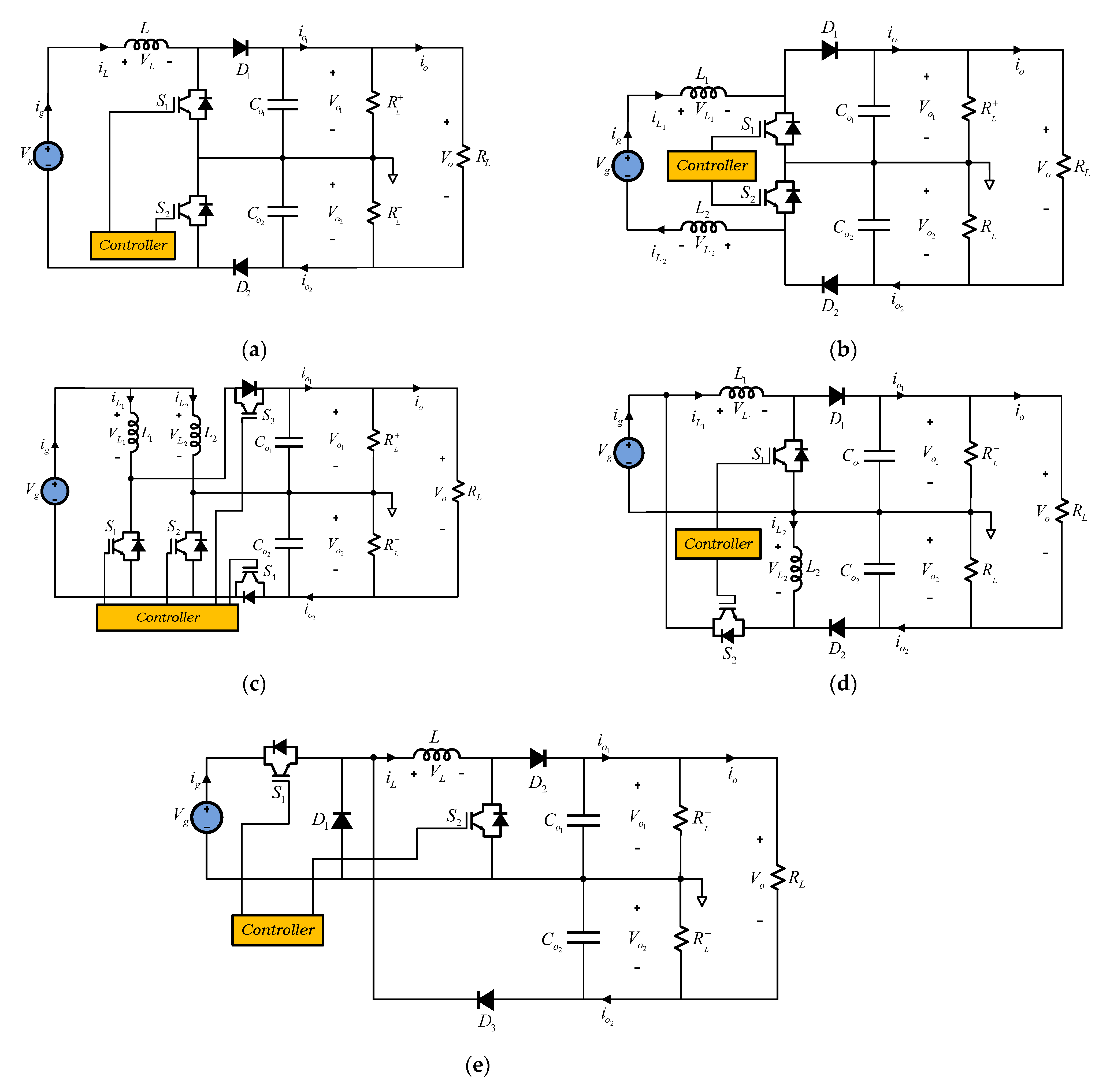
Figure 8. Single Input Dual Output (SIDO) DC–DC Converters. (a) Three-level Single-inductor Boost Converter [69]. (b) Three-level Two-inductors Boost Converter [70]. (c) Dual-output DC–DC Boost Converter [71]. (d) Series-combined Boost and Buck–Boost Converter [72]. (e) Single-inductor Buck–Boost Converter [73].
SIMO non-isolated with single-switch converters [78][79][80] try to avoid some of the disadvantages of using multiple controlled switches. They are also based on the combination of SISO structures, using their front end, as shown in Figure 9 and Figure 10. In these cases, each output voltage is a function of the duty cycle of the single switch, operation modes (CCM and DCM) and of the combined configuration.
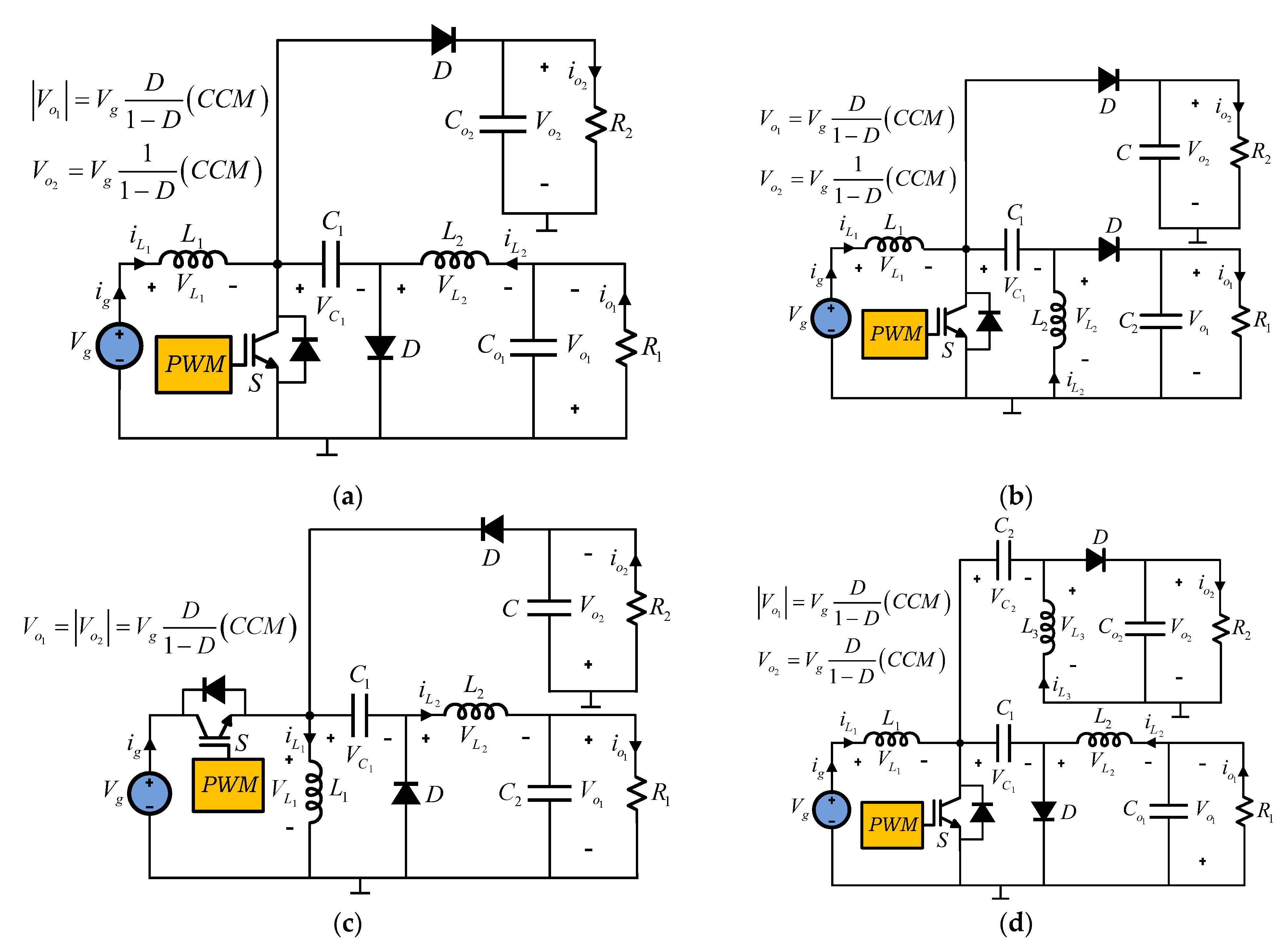
Figure 9. Two-output-type converter combinations. (a) Boost–Ćuk converter combination. (b) Boost–SEPIC converter combination. (c) Buck–Boost–Zeta converter combination. (d) SEPIC–Ćuk converter combination.
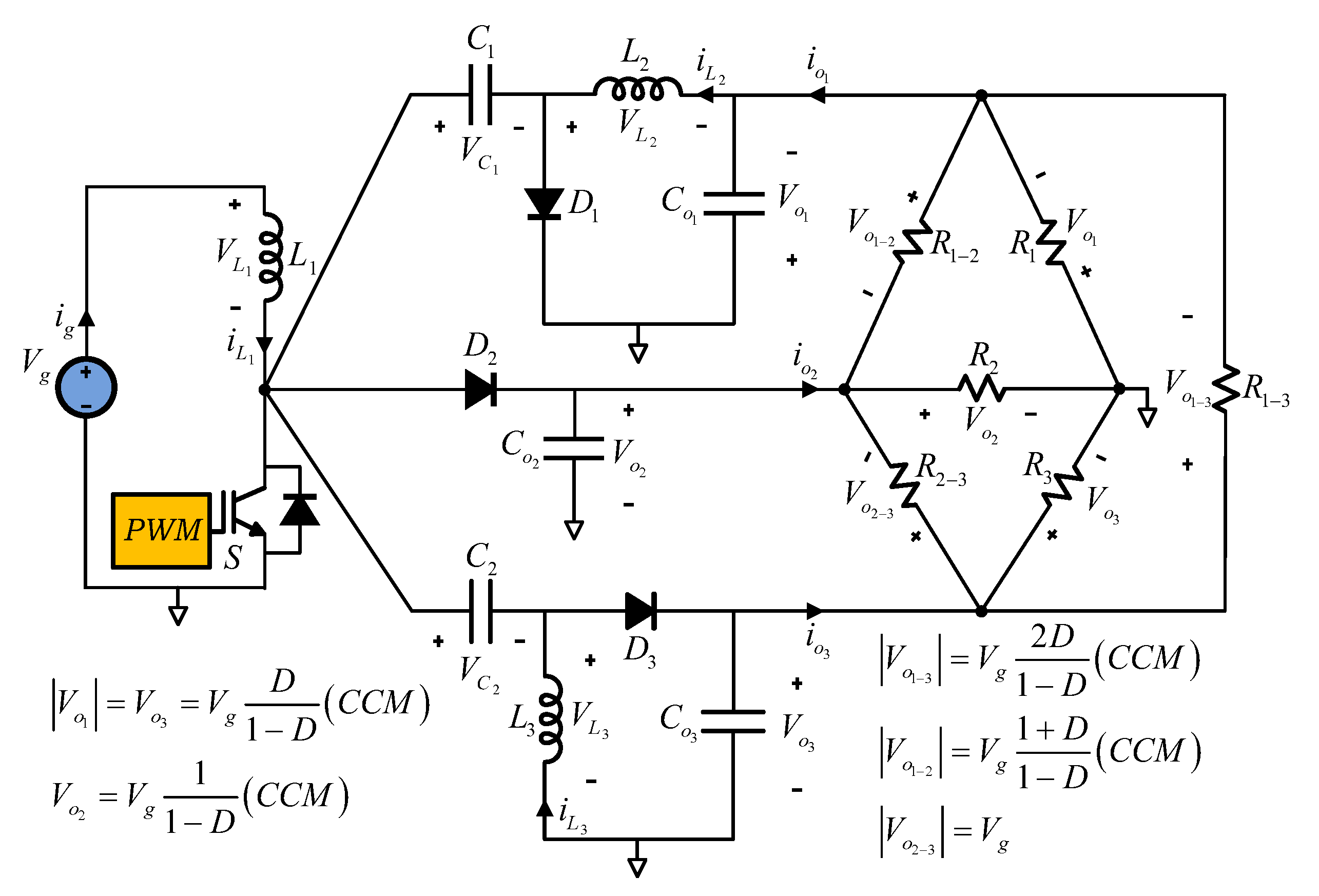
Figure 10. Three-output-type converter combination for six loads.
2.3. MIMO DC–DC Converters Isolated
In the same way, MIMO DC–DC converters for combining various output loads and input sources, they have become an interesting alternative in recent years, especially because they allow the integration of different sources, such as: Rectifiers, Photovoltaic Systems, Fuel Cells, Batteries, Supercapacitors, and, in some cases, Wind Energy Systems. Fundamentally, MIMO converters are implemented according with two structures: sharing a high voltage or low voltage common DC bus; and sharing one or more transformers; or both architectures are also possible.
MIMO isolated configurations use a multi-winding transformer to transfer the energy from the primary side to the secondary side and to couple the different sources and loads, with several power switches and centralized or distributed control signals. Several configurations can be derived from Full-Bridge, Half-Bridge Push–Pull Forward and Flyback topologies, and other such as those shown in Figure 11 [81][82]. These converters consist of Boost, Half-Bridge, or the called Boost–Dual-Half-Bridge (BDHB) topologies. In these converters, the conversion ratio and output voltages depend on the control strategy of the power switches, operation modes, and the turns ratio between the transformer windings. Normally, the power switches are controlled by phase-shifted PWM operating at 50% duty cycle, in CCM and DCM.
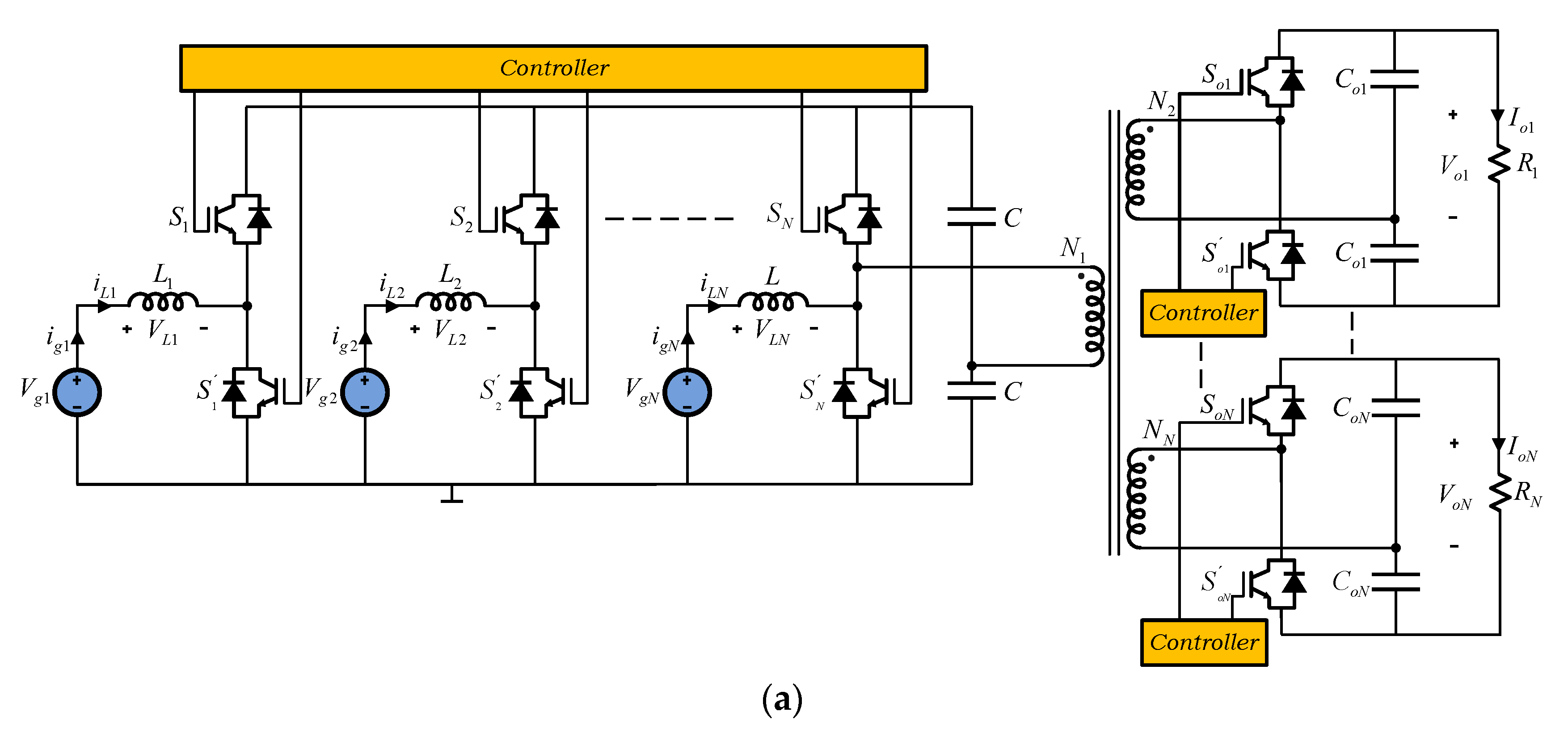
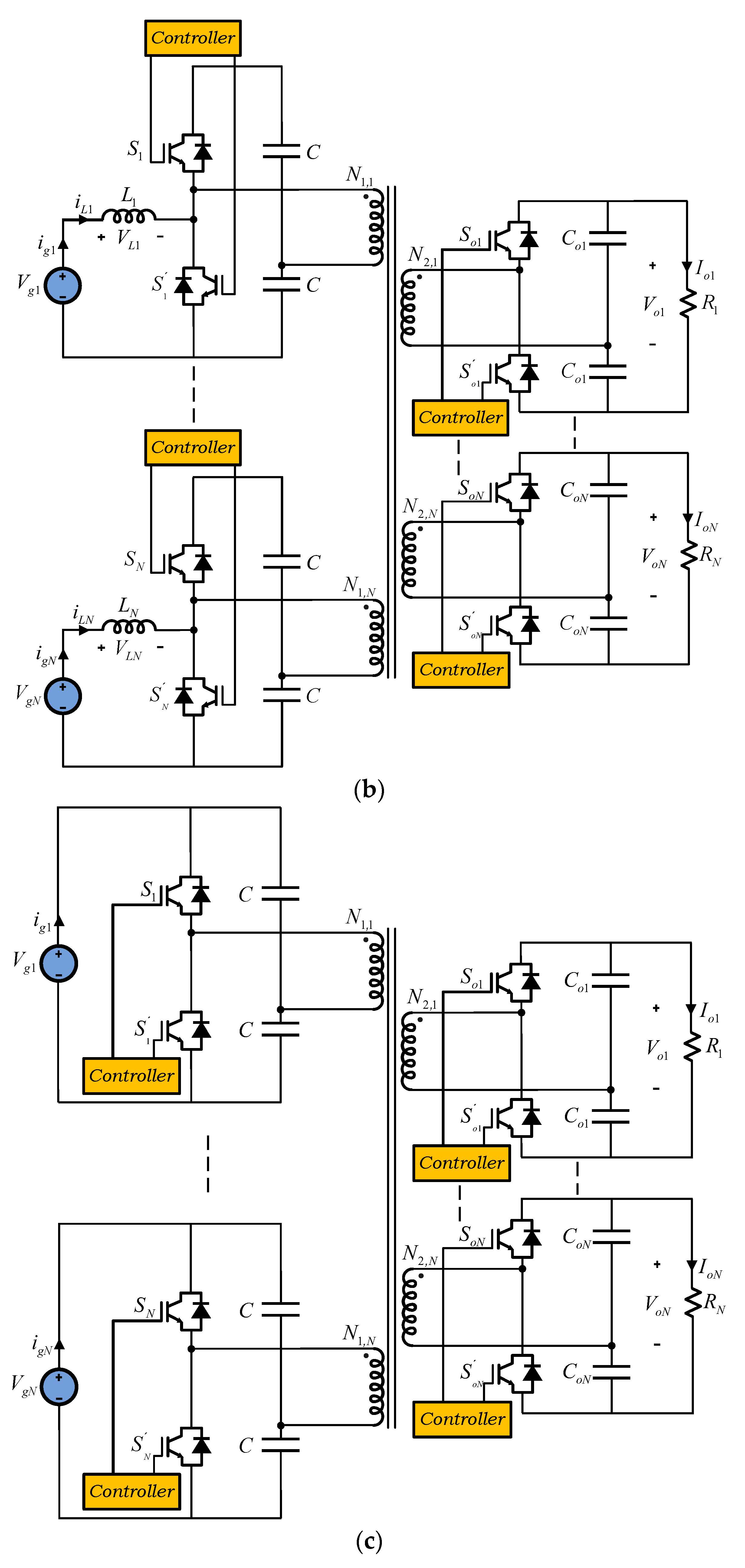
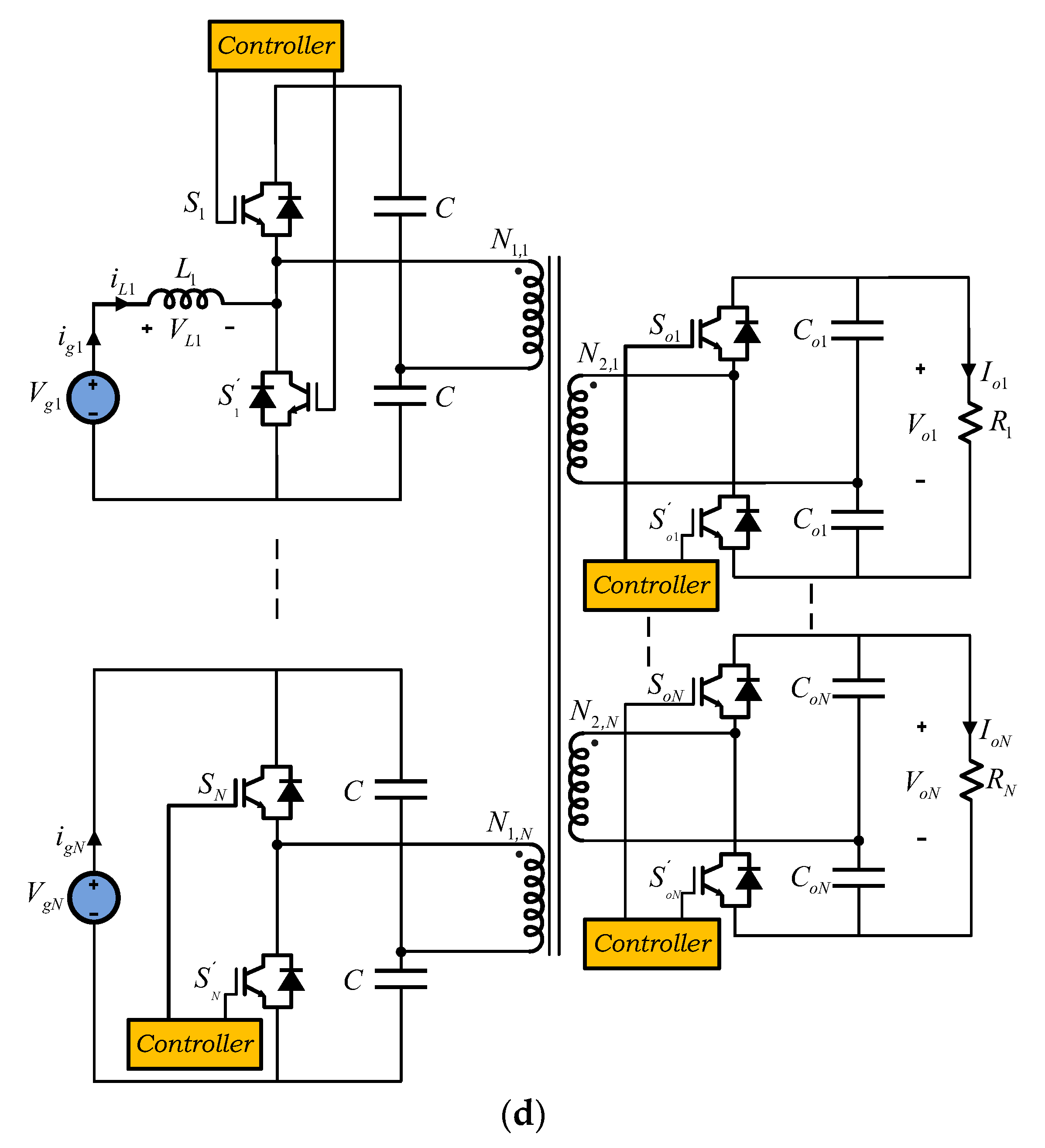
Figure 11. MIMO isolated. (a) Boost parallel converter. (b) Boost ports converter. (c) Half-Bridge converter. (d) Boost–Half-Bridge converter combination.
2.4. MIMO DC–DC Converters Non-Isolated
In the same sense, for MIMO transformerless configurations, based on high-voltage or low-voltage common DC bus, two architectures are established: independent and/or integrated DC–DC converters. MIMO non-isolated integrated uses a single conversion stage, simplifying architecture and control, and have been proposed as an alternative to independent architecture connection. These converters are based on single-input single-output configurations such as: Boost, Buck, Buck–Boost, SEPIC, and Ćuk, as well as combinations of these configurations, with common ground [83][84][85] or series connections [44][86], as shown in Figure 12.
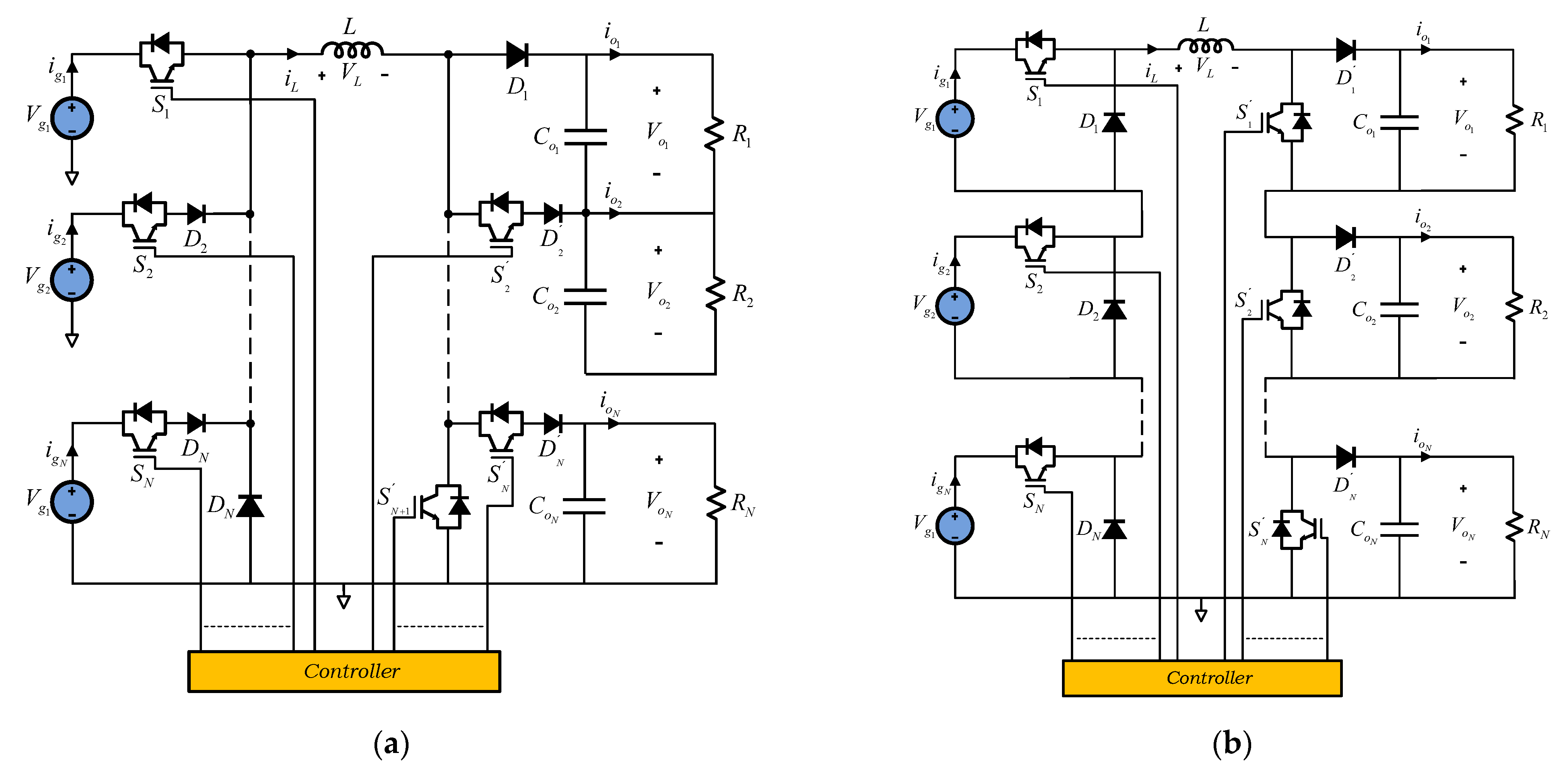
Compared with independent architecture connection, integrated MIMO DC–DC converters have the advantage of smaller size, fewer power conversion stages, and lower cost. On the other hand, both the series inputs and the series inputs and series outputs connection, with a single inductor, require a complex control system to avoid cross-regulation problems, and the simultaneous application of different voltages coming from the input sources, which limits the connection of a large number of sources and loads.
The current trend in the development of DC–DC converters with multiple outputs follows general aspects, such as low losses, high-power density, and high efficiency, as well as the development of new architectures and control strategies. Certainly, simple structures with a reduced number of components and power switches will be one of the new trends, especially to reduce the size. However, the incorporation of devices with a Wide Band Gap (WBG), particularly Gallium Nitride (GaN) and Silicon Carbide (SiC), will establish future trends, advantages and disadvantages, in the development and applications of DC–DC converters with multiple outputs.
References
- Ballestín-Fuertes, J.; Muñoz-Cruzado-Alba, J.; Sanz-Osorio, J.F.; Laporta-Puyal, E. Role of Wide Bandgap Materials in Power Electronics for Smart Grids Applications. Electronics 2021, 10, 677.
- 360 Market Updates. Available online: https://www.360marketupdates.com/ (accessed on 1 April 2022).
- Absolute Reports. Available online: https://www.absolutereports.com/ (accessed on 1 April 2022).
- Allied Market Research. Available online: https://www.alliedmarketresearch.com/ (accessed on 1 April 2022).
- DataM Intelligence. Available online: https://www.datamintelligence.com/ (accessed on 1 April 2022).
- IDTechEx Research Reports. Available online: https://www.idtechex.com/ (accessed on 1 April 2022).
- Market Research Future. Available online: https://www.marketresearchfuture.com/ (accessed on 1 April 2022).
- Market Research Reports, Business Communications Company (BCC). Available online: https://www.bccresearch.com/ (accessed on 1 April 2022).
- Omdia Research by Market. Available online: https://omdia.tech.informa.com/ (accessed on 1 April 2022).
- Report Linker. Available online: https://www.reportlinker.com/ (accessed on 1 April 2022).
- Valuates Reports. Available online: https://reports.valuates.com/ (accessed on 1 April 2022).
- eeNews Europe (Electronics Europe News). Available online: https://www.eenewseurope.com/search/node/multiple%20output%20dc-dc%20converters (accessed on 1 April 2022).
- eeNews Embedded. Available online: https://www.eenewsembedded.com/search/node/multiple%20output%20dc-dc%20converters (accessed on 1 April 2022).
- Electronics Design eNewsletter. Available online: https://www.electronicdesign.com/search?ebm_electronicdesign%5Bquery%5D=multiple%20output%20dc-dc%20converters (accessed on 1 April 2022).
- EE Times Europe Magazine. Available online: https://www.eetimes.eu/?s=multiple+output+dc-dc+converters (accessed on 1 April 2022).
- Power Electronics News. Available online: https://www.powerelectronicsnews.com/?s=multiple+output+dc-dc+converters (accessed on 1 April 2022).
- Smart2.0. Available online: https://www.smart2zero.com/search/node/multiple%20output%20dc-dc%20converters (accessed on 1 April 2022).
- DC–DC Converter Market by Vertical, Form Factor (SIP, DIP, DIN Rail, Box, Chassis Mount, Discreter, Brick), Input Voltage, Output Voltage, Output Power, Output Number, Product Type, Isolation Working Voltage and Region-Forecast to 2026. Available online: https://www.researchandmarkets.com/reports/5401801/dc-dc-converter-market-by-vertical-form-factor?utm_source=MC&utm_medium=Email&utm_code=mzrfk4g55&utm_ss=44&utm_campaign=1589384+-+dc-dc+converter+Market+-+Forecast+to+2026&utm_exec=cono266mtd (accessed on 1 April 2022).
- Global Switching Power Supply Market Size, Trends & Growth Opportunity, by Voltage Rating, by Application, by Region and Forecast to 2027. Available online: https://www.researchandmarkets.com/reports/5437868/global-switching-power-supply-market-size-trends?utm_source=MC&utm_medium=Email&utm_code=mzrj5rgey&utm_ss=44&utm_campaign=1587831+-+Global+Switching+Power+Supply+Market+Size%2c+Trends+%26+Growth+Opportunity%2c+and+Forecast+to+2027&utm_exec=cono266mtd (accessed on 1 April 2022).
- Global DC–DC Converters Market Research Report 2021, Forecast to 2026. Available online: https://www.360marketupdates.com/global-DC–DC-converters-market-19159087 (accessed on 1 April 2022).
- Rugged Power Supply Market Global Industry Analysis, Size, Share, Growth, Trends, and Forecast 2017–2025. Available online: https://www.bccresearch.com/partners/transparency/rugged-power-supply-market-global-industry-analysis-size-share-growth-trends-and-forecast.html (accessed on 1 April 2022).
- Medical Power Supply Market, Size, Share, Growth, Trends, Insight and Industry Forecast 2021–2028. Available online: https://www.datamintelligence.com/research-report/medical-power-supply-market (accessed on 1 April 2022).
- DC–DC Converter Market by Vertical, Form Factor, Input Voltage, Output Voltage, Output Power, Output Number, Product Type, Isolation Working Voltage and Region-Forecast to 2026. Available online: https://www.reportlinker.com/p04180622/Global-dc-dc-Converters-Market-by-Application-Output-Number-Input-Voltage-Output-Voltage-Output-Power-Sales-Channel-Form-Factor-Product-Type-and-Region-Forecast-to.html (accessed on 1 April 2022).
- 5G Small Cells 2021–2031: Technologies, Markets, Forecast. Available online: https://www.idtechex.com/en/research-report/5g-small-cells-2021-2031-technologies-markets-forecast/825 (accessed on 1 April 2022).
- LED Supply & Demand Market Tracker—1Q21 Analysis. Available online: https://omdia.tech.informa.com/OM018423/LED-Supply--Demand-Market-Tracker--1Q21-Analysis (accessed on 1 April 2022).
- Rugged Power Supply Market Research Report, by Component (Hardware and Software), System Type (Discrete and Integrated), Industry Vertical (Defense, Aerospace, Telecommunications, Manufacturing, Healthcare, and Transportation)—Forecast till 2027. Available online: https://www.marketresearchfuture.com/reports/rugged-power-supply-market-7150 (accessed on 1 April 2022).
- DC–DC Converter Market by Input Voltage (5–36 V, 36–75 V, 75 V and Above), Output Voltage (3.3 V, 5 V, 12 V, 15 V and Above), Mounting Style (Surface Mount and Through Hole), Application (Smartphone, Servers & Storage, EV Battery Management Unit, Railway, and Medical Equipment): Global Opportunity Analysis and Industry Forecast, 2020–2027. Available online: https://www.alliedmarketresearch.com/dc-dc-converter-market (accessed on 1 April 2022).
- Massive Multiple-Input Multiple-Output (MIMO) Market-Growth, Trends, COVID-19 Impact, and Forecasts (2021–2026). Available online: https://www.mordorintelligence.com/industry-reports/massive-multiple-input-multiple-output-mimo-market (accessed on 1 April 2022).
- Global Power Supply Unit for Servers Market Size, Manufacturers, Supply Chain, Sales Channel and Clients, 2021–2027. Available online: https://reports.valuates.com/market-reports/QYRE-Auto-15M6756/global-power-supply-unit-for-servers (accessed on 1 April 2022).
- Global Switching Power Supply Market 2021 by Manufacturers, Regions, Type and Application, Forecast to 2026. Available online: https://www.absolutereports.com/global-switching-power-supply-market-19180193 (accessed on 1 April 2022).
- Aimtec. Available online: http://www.aimtec.com/manufacture-modular-ac-dc-dc-dc-switching-power-supplies (accessed on 1 April 2022).
- CUI. Available online: https://www.cui.com/catalog/dc-dc-converters (accessed on 1 April 2022).
- Delta Electronics. Available online: https://www.deltaww.com/en-US/products/dc-dc/ALL/ (accessed on 1 April 2022).
- Flex Ltd. Available online: https://flexpowermodules.com/ (accessed on 1 April 2022).
- Infineon Technologies AG. Available online: https://www.infineon.com/cms/en/product/power/dc-dc-converters/ (accessed on 1 April 2022).
- Maxim Integrated. Available online: https://www.maximintegrated.com/en/products/power/switching-regulators.html (accessed on 1 April 2022).
- MORNSUN Power. Available online: https://www.mornsun-power.com/html/products/1986/switching-regulator.html (accessed on 1 April 2022).
- Murata Power Solutions. Available online: https://www.murata.com/products/power (accessed on 1 April 2022).
- TDK Lambda. Available online: https://www.us.lambda.tdk.com/products/dcdc-converters/ (accessed on 1 April 2022).
- Texas Instruments. Available online: https://www.ti.com/power-management/overview.html (accessed on 1 April 2022).
- Traco Power. Available online: https://www.tracopower.com/dc-dc-converters (accessed on 1 April 2022).
- Vicor Corporation. Available online: https://www.vicorpower.com/dc-dc (accessed on 1 April 2022).
- Saman, D.T.; Peng, Z.; Lu, X.; Mohsen, H. Mutual Interactions and Stability Analysis of Bipolar DC Microgrids. CSEE J. Power Energy Syst. 2019, 5, 444–453.
- Behjati, H.; Davoudi, A. A Multiple-Input Multiple Output DC–DC Converter. IEEE Trans. Ind. Appl. 2013, 49, 1464–1479.
- Tong, Y.; Shan, Z.; Jatskevich, J.; Davoudi, A. Anonisolated multiple-input multiple-output dc–dc converter for dc distribution of future energy efficient homes. In Proceedings of the IEEE 40th Annual Conference of the Industrial Electronics Society, Dallas, TX, USA, 29 October–1 November 2014; pp. 4126–4132.
- Taehyung, K.; Sangshin, K. Single pole switch leg based multi-port converter with an energy storage. Power Electron. IET 2016, 9, 1322–1330.
- Patra, P.; Patra, A.; Misra, N. A single-inductor multiple-output switcher with simultaneous Buck, Boost, and inverted out-puts. IEEE Trans. Power Electron. 2012, 27, 1936–1951.
- Huang, M.H.; Chen, K.H. Single-inductor multi-output (SIMO) DC–DC converters with high light-load efficiency and mini-mized cross regulation for portable devices. IEEE J. Solid-State Circuits 2009, 44, 1099–1111.
- Dhananjaya, M.; Swapnajit, P. Design and implementation of a SIMO DC–DC converter. IET Power Electron. 2019, 12, 1868–1879.
- Dietrich, S.; Strache, S.; Wunderlich, R.; Heinen, S. Get the LED out: Experimental validation of a capacitor-free single-inductor, multiple-output LED driver topology. IEEE. Ind. Electron. Mag. 2015, 9, 24–35.
- Nami, A.; Zare, F.; Ghosh, A.; Blaabjerg, F. Multi-output dc–dc converters based on diode clamped converters configuration: Topology and control strategy. IET Power Electron. 2010, 3, 197–208.
- Lindiya, S.A.; Subashini, N.; Vijayarekha, K. Cross Regulation Reduced Optimal Multivariable Controller Design for Single Inductor DC–DC Converters. Energies 2019, 12, 477.
- Abraham, D.S.; Verma, R.; Kanagaraj, L.; Raman, S.G.T.; Rajamanickam, N.; Chokkalingam, B.; Sekar, K.M.; Mihet-Popa, L. Electric Vehicles Charging Stations’ Architectures, Criteria, Power Converters, and Control Strategies in Microgrids. Electronics 2021, 10, 1895.
- Bose, B. Need a Switch? IEEE Ind. Electron. Mag. 2007, 1, 30–39.
- Outeiro, M.T.; Buja, G.; Czarkowski, D. Resonant Power Converters: An Overview with Multiple Elements in the Reso-nant Tank Network. IEEE Ind. Electron. Mag. 2016, 10, 21–45.
- Salem, M.; Jusoh, A.; Idris, N.R.; Das, H.S.; Alhamrouni, I. Resonant power converters with respect to passive storage (LC) ele-ments and control techniques—An overview. Renew. Sustain. Energy Rev. 2018, 91, 504–520.
- Li, T. Single Inductor Multiple Output Boost Regulator. U.S. Patent 6,075,295A, 13 June 2000.
- Ma, D.; Ki, W.-H.; Mok, P.K.T.; Tsui, C.-Y. Single-inductor multiple-output switching converters. Proc. IEEE PESC 2001, 1, 226–231.
- Ma, D.; Ki, W.-H.; Tsui, C.-Y. A pseudo-CCM/DCM SIMO switching converter with freewheel switching. IEEE J. Solid-State Circuits 2003, 38, 1007–1014.
- Soyka, R.; Rall, W.; Schnaubelt, J.; Sieger, P.; Kulinna, C. Process for Preparing Amino Crotonyl Compounds. U.S. Patent 20,050,085,495A1, 21 April 2005.
- Le, H.-P.; Chae, C.-S.; Lee, K.-C.; Wang, S.-W.; Cho, G.-H. A Single-Inductor Switching DC–DC Converter with Five Outputs and Ordered Power-Distributive Control. IEEE J. Solid-State Circuits 2007, 42, 2706–2714.
- Seol, K.-S.; Woo, Y.-J.; Cho, G.-H.; Gho, G.-H.; Lee, J.-W. A synchronous multioutput step-up/down dc–dc converter with return current control. IEEE Trans. Circuits Syst. II Exp. Briefs 2009, 56, 210–214.
- Kwon, D.; Rincon-Mora, G.A. Single-Inductor–Multiple-Output Switching DC–DC Converters. IEEE Trans. Circuits Syst. II Express Briefs 2009, 56, 614–618.
- Goder, D.; Santo, H. Multiple Output Regulator with Time Sequencing. U.S. Patent 5,617,015, 1 April 1997.
- Ma, D.; Ki, W.-H.; Tsui, C.Y.; Mok, P.K.T. Single-inductor multiple-output switching converters with time-multiplexing control in discontinuous conduction mode. IEEE J. Solid-State Circuits 2003, 38, 89–100.
- Li, X.L.; Dong, Z.; Tse, C.K. Complete family of two-stage singleinput multi-output configurations of interconnected power converters. IEEE Trans. Power Electron. 2020, 35, 3713–3728.
- Litrán, S.P.; Durán, E.; Barroso, R.S.; Semião, J.; Ferrera, M.B. Analysis of Converters with Bipolar Output for DC Mi-crogrid. In Proceedings of the 2020 IEEE 14th International Conference on Compatibility, Power Electronics and Power Engineering (CPE-POWERENG), Setubal, Portugal, 8–10 July 2020; pp. 13–18.
- Kakigano, H.; Miura, Y.; Ise, T. Low-Voltage Bipolar-Type DC Microgrid for Super High Quality Distribution. IEEE Trans. Power Electron. 2010, 25, 3066–3075.
- Zhang, M.; Jiang, Y.; Lee, F.; Jovanovic, M. Single-phase three-level boost power factor correction converter. In Proceedings of the 1995 IEEE Applied Power Electronics Conference and Exposition-APEC’95, Dallas, TX, USA, 5–9 March 1995; Volume 1, pp. 434–439.
- Haddad, K. Three level DC–DC converters as efficient interface in two stage PV power systems. In Proceedings of the 2012 IEEE Energytech, San Diego, CA, USA, 29–31 May 2012; pp. 1–6.
- Rezayi, S.; Iman-Eini, H.; Hamzeh, M.; Bacha, S.; Farzamkia, S. Dual-output DC/DC boost converter for bipolar DC microgrids. IET Renew. Power Gener. 2019, 13, 1402–1410.
- Durán-Gómez, J.L.; García-Cervantes, E.; López-Flores, D.R.; Enjeti, P.N.; Palma, L. Analysis and evaluation of a series-combined connected boost and buck-boost DC–DC converter for photovoltaic application. In Proceedings of the Twenty-First Annual IEEE Applied Power Electronics Conference and Exposition, 2006, APEC’06, Dallas, TX, USA, 19–23 March 2006; pp. 19–23.
- Schoenbauer, S.; Martin-Lopez, F.R. Single Inductor Buck Boost Converter with Positive and Negative Outputs. U.S. Patent 20,100,039,080, 18 February 2010.
- Kang, H.; Cha, H. A New Nonisolated High-Voltage-Gain Boost Converter with Inherent Output Voltage Balancing. IEEE Trans. Ind. Electron. 2017, 65, 2189–2198.
- Prabhakaran, P.; Agarwal, V. Novel Boost-SEPIC Type Interleaved DC–DC Converter for Mitigation of Voltage Imbalance in a Low-Voltage Bipolar DC Microgrid. IEEE Trans. Ind. Electron. 2019, 67, 6494–6504.
- Kumar, P.; Singh, R.K.; Mahanty, R. Performance of MPPT-Based Minimum Phase Bipolar Converter for Photovoltaic Systems. IEEE Trans. Power Electron. 2021, 36, 5594–5609.
- Zhou, X.; Wang, Y.; Wang, L.; Liu, Y.-F.; Sen, P.C. A Soft-Switching Transformerless DC−DC Converter with Single-Input Bipolar Symmetric Outputs. IEEE Trans. Power Electron. 2021, 36, 8640–8646.
- Sanjeevikumar, P.; Bhaskar, M.S.; Dhond, P.; Blaabjerg, F.; Pecht, M. Non-isolated Sextuple Output Hybrid Triad Converter Configurations for High Step-Up Renewable Energy Applications. In Advances in Power Systems and Energy Management. Lecture Notes in Electrical Engineering; Springer: Singapore, 2018; Volume 436, pp. 1–12.
- Durán, E.; Litrán, S.P.; Ferrera, M.B. Configuration of DC–DC converters of one input and multiple outputs without trans-former. IET Power Electron. 2020, 13, 2658–2670.
- Ferrera Prieto, M.B.; Litran, S.P.; Aranda, E.D.; Gomez, J.M.E. New Single-Input, Multiple-Output Converter Topologies: Combining Single-Switch Nonisolated DC–DC Converters for Single-Input, Multiple-Output Applications. IEEE Ind. Electron. Mag. 2016, 10, 6–20.
- Tao, H.; Kotsopoulos, A.; Duarte, J.; Hendrix, M. Family of multiport bidirectional DC–DC converters. IEE Proc.-Electr. Power Appl. 2006, 153, 451–458.
- Tao, H.; Kotsopoulos, A.; Duarte, J.; Hendrix, M. Multi-input bidirectional DC–DC converter combining DC-link and magnetic-coupling for fuel cell systems. In Proceedings of the Fourtieth IAS Annual Meeting. Conference Record of the 2005 Industry Applications Conference, Hong Kong, China, 2–6 October 2005.
- Li, X.L.; Dong, Z.; Tse, C.K.; Lu, D.D.-C. Single-Inductor Multi-Input Multi-Output DC–DC Converter with High Flexi-bility and Simple Control. IEEE Trans. Power Electron. 2020, 35, 13104–13114.
- Dong, Z.; Li, Z.; Lucia, X.; Chi, L.; Tse, K.; Zhang, Z. Single-Inductor Multiple-Input Multiple-Output Con-verter With Common Ground High Scalability and No Cross-Regulation. Power Electron. IEEE Trans. 2021, 36, 6750–6760.
- Chen, G.; Liu, Y.; Qing, X.; Ma, M.; Lin, Z. Principle and Topology Derivation of Single-Inductor Multi-Input Multi-Output DC–DC Converters. IEEE Trans. Ind. Electron. 2021, 68, 25–36.
- Nguyen, B.L.-H.; Cha, H.; Nguyen, T.T.; Kim, H.G. Family of integrated multi-input multi-output DC–DC power converters. In Proceedings of the 2018 International Power Electronics Conference (IPEC-Niigata 2018-ECCE Asia), Niigata, Japan, 20–24 May 2018; pp. 3134–3139.
More
Information
Subjects:
Engineering, Electrical & Electronic
Contributors
MDPI registered users' name will be linked to their SciProfiles pages. To register with us, please refer to https://encyclopedia.pub/register
:
View Times:
4.1K
Revisions:
2 times
(View History)
Update Date:
27 Apr 2022
Table of Contents


Notice
You are not a member of the advisory board for this topic. If you want to update advisory board member profile, please contact office@encyclopedia.pub.
OK
Confirm
Only members of the Encyclopedia advisory board for this topic are allowed to note entries. Would you like to become an advisory board member of the Encyclopedia?
Yes
No
${ textCharacter }/${ maxCharacter }
Submit
Cancel
Back
Comments
${ item }
|
${ item.createdUser.fullName }
${ item.createdAt }
${ item.vote }
${ item.reply }
Delete
${ reply.createdUser.fullName }
${ reply.createdAt }
${ reply.vote }
Delete
There is no reply to this comment~
${ item.replyTextCharacter }/${ item.replyMaxCharacter }
Submit
Cancel
More
No more~
There is no comment~
${ textCharacter }/${ maxCharacter }
Submit
Cancel
${ selectedItem.replyTextCharacter }/${ selectedItem.replyMaxCharacter }
Submit
Cancel
Confirm
Are you sure to Delete?
Yes
No