Multiple-output DC–DC converters are fundamental in electric power supply, distribution, management, and power delivery systems. They are essential in applications such as: Intermediate Bus Architecture (IBA), Distributed Power Architectures (DPA), Dynamic Bus Architecture (DBA), Central Control Architecture (CCA), Datacom and Telecom, Light-Emitting Diodes (LEDs), consumer electronics products, battery chargers, or even Electric Vehicles (EV). These converters are used for USB power delivery, I/O, CPUs, FPGAs, ASICs, and other low-voltage devices, applications where controllability, efficiency, reliability, and miniaturization are critical.
Undoubtedly, the development of power switch semiconductor technologies has also contributed significantly to more efficient switching and has facilitated a higher frequency operation. This has allowed the development of applications where multiple-output DC–DC converters are used, considering mainly three aspects: high-power density, high efficiency, and small size. The increase in the rating of power devices, such as Insulated Gate Bipolar Transistors (IGBT) and Metal-Oxide-Semiconductor Field-Effect Transistor (MOSFET) technologies, has allowed innumerable applications to be addressed in the last 40 years. They have helped to improve energy efficiency and CO2 reductions, in commercial, residential, transportation systems, industrial, military, aerospace, computer systems, lighting, and vehicle applications. MOSFET and IGBT, either as power modules or within discrete devices, have been the preferred technologies for high and medium power applications. IGBTs are used in applications of high-current, with voltages over 1 kV and up to 10 kVA, while MOSFETs are used in applications below 1 kV, but they are the most suitable in applications of high switching frequency, between 10–100 kHz.
All these applications contemplate various aspects and types of DC–DC converters, such as output number (dual-output, bipolar output, three- and four-output-type converters), power (<1 kW, 1–10 kW, 10–20 kW, and >20 kW) including low, medium, and high power, input voltage (<40 V, 40–70 V, and >70 V), output voltage (24 V, 15 V, 12 V, 5 V, and 3.3 V), isolated (one switch, two switches, and four switches converters) and non-isolated (one switch or several switches) DC–DC converters. In low-power applications, the two main trends are related to high-power density and low voltage, while in high power, with high efficiency and reliability. But the main trend is related to miniaturization for integration. Small size and weight, together with high-power density are very important items in power supplies for small format applications, mobile electronic systems, and onboard systems, driven by applications with facilities with space restrictions such as More-Electric Aircraft (MEA), Electric Vehicle (EV), Robotics, Electric Ship (ES), Robotics, Solid-State Lighting, Integrated DC–DC Power Supply and Monolithic Power Systems, Intelligent DC–DC Power Distribution (micro or nano grids), On-chip Power Supply, Wireless Remote Sensing Node and Power Transfer, New Transport Technologies, Energy Harvesting, and IoT. In these applications, multiple or single power systems are used, which distribute energy to different loads, with converters operating in power ranging from hundreds of kilowatts to a few watts. This focus on multiple-output DC–DC converter applications has also led to the development and commercialization of integrated solutions by many electronic manufacturers [
31,
32,
33,
34,
35,
36,
37,
38,
39,
40,
41,
42], and to different tutorials, webinars, on-line publications, white papers and some surveys, reviews, and overviews papers being reported in the literature.
2. Multiple-Output DC–DC Converters: Topologies and Configurations
The main objective of DC–DC power conversion is to transfer electric power from a DC source into another DC source, which can be a load, with the highest efficiency and therefore lowest losses. The DC–DC converters are widely used at all power levels (from mW to kW), current levels (from nA to hundreds of amps) and voltage levels (from mV to kV) and have been very popular for the last three decades, they can invert the polarity of the DC voltage and increase or decrease its magnitude. The topologies and properties of DC–DC converters are reported in the literature and are well known. Topology describes how source, load, inductive and capacitive elements, and switches are interconnected in the converter, while the configuration establishes the DC conversion relation between the input and output current/voltage and according to the operating mode and the converter topology. Efficiency depends on how close converter elements are to ideal condition; assuming that the same elements are available, efficiency is related to the converter topology. Switch electrical stress (current and voltage) decides the choice of semiconductor devices used to implement the switches. For lower losses on parasitic resistances, lower generated noise, and more efficient filtering, it is preferred that input and output waveforms be continuous (ideally, DC only). Complexity of a converter is measured by the number of inductors, capacitors, and switches. Efficiency and density (watts/volume) have long been the metrics used to compare the performance of power converters.
DC–DC converters can be classified depending on the number of inputs as Multiple-Input and Single-Output (MISO), or Single-Input and Single-Output (SISO), depending on the number of outputs as Single-Input and Multiple-Output (SIMO), or Multiple-Input and Multiple-Output (MIMO). In all cases, they can provide one or more output voltages, from one or more input voltages. Multiple-output DC–DC converters are of interest in applications that require several outputs, from one or more input voltages, which include configurations MIMO [
43,
44,
45,
46] and SIMO [
47,
48,
49,
50,
51].
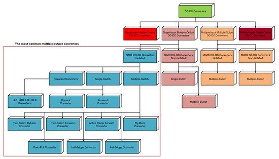
As it is showed in Figure 1, SIMO DC–DC converters can be classified into isolated and non-isolated, depending on whether they are implemented with or without an electrical isolation, by means of a transformer, generally operated at high frequency. The output/input power range is often used as the main aspect when selecting a topology. However, there are many other factors that influence the topology selection for an isolated multi-output DC–DC power converter, such as: electrical stress, size, cost, input voltage range, and output noise. The size of an isolated multi-output power converter mainly depends on the transformer size and the number of active switches employed, while for a non-isolated converter depends on the number of active switches employed. The utilization of the power transformer affects the size of the power converter. A high-frequency transformer provides galvanic isolation between input and output, and allows increasing the step-up conversion ratio, while coupled inductors can also be used to increase the step-up ratio in a DC conversion and provide different output voltages from several secondary windings.
Figure 1. Multiple-Output DC–DC Converters Classification.
Control over DC conversion relation can be obtained by PWM (Pulse-Width Modulation) technique, usually using a Constant Frequency (CF). D (Duty Cycle) is the ratio between TON (Conduction Time) of switch/es and TS (Switching Period). In PWM, the output voltage regulation is corrected (adjusted) by changing the TON of the switching element in the converter. Other control strategies used in DC–DC converters are: Variable Frequency and Constant on-Time (VF-C-on-T), Variable Frequency and Constant off-Time (VF-C-off-T), and variable frequency and variable pulse width. In VF-C-on-T, the operating frequency varies as a function of the input and load current. In VF-C-off-T conduction, the operating frequency varies (implying variable on-time conduction) as a function of the input and load current. CF is usually preferred over VF control since filtering components can be optimized to suppress voltage and current ripples at switching frequency and its harmonics. Also, noise generated by VF converters is more difficult to handle, and, in some applications, it cannot be tolerated. There is a wide variety of modes, techniques (linear and nonlinear), and types of controllers used for DC–DC converters: Voltage Mode Control (VMC), Current Mode Control (CMC), Sliding Mode (SM) or Hysteretic Mode (HM), and Band-Band Control (BBC), and controllers such as PID (Proportional-Integral-Derivative), Fuzzy Logic (FL), and Neural Network (NN) in different variants and their advantages and disadvantages are well understood and described in the literature.
When several outputs must be regulated it appears a mutual Cross Regulation (CR) effect, and this is one of the critical challenges in multi-output converters, when there is a load change in any one or more of its outputs. Among the different techniques implemented to regulate multiple DC outputs, cross regulation technique is very used by its simplicity. In this technique, one of the output voltages is directly sensed by the controller and regulated to the desired value. The other output voltages are indirectly regulated (quasi-regulated) by the main inductor and switch. Of course, the non-controlled outputs have lower regulation capacity and can present a variation with respect to their nominal values (CR = △
Voi/△
Ioj). On the other hand, cross regulation allows the reduction in size, weight, and cost, and circuitry simplicity in several applications since it shows many advantages in terms of flexibility and integration in power-management systems. To suppress cross regulation, some methods have been reported in the literature [
52,
53].
2.1. SIMO DC–DC Converters Isolated
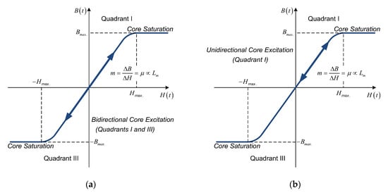
Isolated SIMO DC–DC converter topologies can be denominated as either double-ended or single-ended, based on the use of the magnetization curve (B-H curve, flux density versus magnetic field strength), as shown in Figure 2. During the operation, if the flux oscillates in two quadrants of the B-H curve (Figure 2a), then the topology is called as double-ended. While, if the flux oscillates in only one quadrant of the B-H curve (Figure 2b), then the topology is called as single-ended. In general, for given operating conditions, a single-ended topology requires a greater core than a double-ended topology and needs an additional reset winding.
Figure 2. B-H Curve (without hysteresis) of Transformer Core. (a) Bidirectional Core Excitation. (b) Unidirectional Core Excitation.
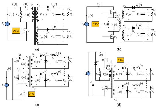
Among Buck and Buck–Boost derived DC–DC converters, the most popular single-switch are Forward and Flyback converter, while those employing multiple switches include Full-Bridge, Half-Bridge, and Push–Pull converter. Figure 3, Figure 4 and Figure 5, show the basic isolated SIMO DC–DC converters. The output filter inductor in Full-Bridge, Half-Bridge, and Push–Pull converters acts as the inductance in a Buck converter, and thus the equation for critical inductance for the Buck is valid for these Buck-Derived converters, as long as the appropriate transformation of the input voltage due to the transformer turns ratio and topology is applied. As a result, Isolated Buck (Fly-Buck) converter is used in applications below 15 W, Flyback, and Buck-Derived converters in 10–100 W, Forward in 50–300 W, Half-Bridge, and Push–Pull converters in more than 500 W, while Full-Bridge is used in applications with a power range of 1 to 5 kW.
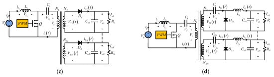
Figure 3. Multiple-Output Isolated DC–DC Converters Topologies. (a) Single-Switch Flyback Converter. (b) Two-Switch Flyback Converter. (c) Single-Switch Forward Converter. (d) Two-Switch Forward Converter.
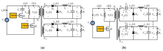
Figure 4. Multiple-Output Isolated DC–DC Converters Topologies. (a) Active Clamp Forward Converter. (b) Isolated Zeta Converter. (c) Isolated SEPIC Converter. (d) Isolated Ćuk Converter.
Figure 5. Multiple-Output Isolated DC–DC Converters Topologies. (a) Isolated Buck (Fly-Buck) Converter. (b) Half-Bridge Converter. (c) Push–Pull Converter. (d) Full-Bridge Converter.
Other classification of isolated multiple-output DC–DC converters can be realized depending on the switching technique: hard-switching (PWM converters) and soft-switching (resonant converters) [
54,
55,
56]. They are traditionally used in applications such as very high frequency power supplies, induction heating, ballasts for fluorescent lamps, sonar transmitters, ultrasonic generators, and power supplies for laser cutting machines. Isolated resonant converters can be defined as converter networks to which resonant (
L and
C) elements are added. In contrast to square wave switch waveforms in PWM converters, resonant topologies exhibit smooth quasi-sinusoidal waveforms and, therefore, reduced switching losses. The incentive to increase the frequency at which DC–DC converters are operated is motivated by the fact that correspondingly smaller values and, hence, weights and sizes of energy storage components should result in lighter and smaller converters. However, the inevitable increase in power losses due to switching establishes a practical upper limit in the frequency range. Resonant isolated converter topologies overcome some of the switching loss mechanisms attributed to PWM converters and offer the possibility of extending the usable frequency range toward higher frequencies (typically 100 to 500 kHz). In contrast to sharp transitions in current and voltage waveforms of PWM converters, the resonant converters operate with smooth, quasi-sinusoidal, resonant waveforms, leading to reduced losses ascribed to switching transitions. Soft-switching converters can exhibit reduced switching loss, at the expense of increased conduction loss.
Resonant converters use resonant L-C elements that cause sinusoidal variation of voltage and current waveforms in order to reduce switching losses. They were developed as an alternative to simple rectangular switching, the power devices switch at high frequency, maintaining acceptable converter efficiency by minimizing the significant switching losses associated with hard-switching. In these converters, the size and weight are reduced (mainly, magnetic and filtering components) and the power density is increased, with low stress on the switching devices. In addition, the soft-switching technique utilizes Variable Frequency (VF) for regulation, with constant on-time or constant off-time, which creates an oscillating circuit that allows power device transitions to occur at zero voltage (Zero Voltage Switching, ZVS) or zero current (Zero Current Switching, ZCS), eliminating or reducing the switching losses in the converter, higher-frequency operation and reducing the size of magnetic and filter components. Both resonant techniques are widely used in many applications.
In isolated multiple-output DC–DC converters, the resonant components can be placed either on the primary or on the secondary side. When a resonant capacitor is placed on in some winding, the leakage inductance and magnetizing inductance of the transformer can be used as a resonant element in order to reduce the number of discrete magnetic components and, therefore, increase the power density of the converter.
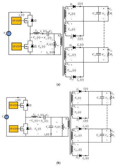
Although there is a wide variety of isolated multiple-output resonant converter topologies, the most widely used are those based on three reactive elements, being LLC and LCC, shown in Figure 6, the most popular.
Figure 6. Three-element Multiple-Output Isolated Resonant DC–DC Converters: LLC and LCC. (a) LLC Resonant DC–DC Converter. (b) LCC Resonant DC–DC Converter.
2.2. SIMO DC–DC Converters Non-Isolated
Multiple-output converters without transformers are an alternative in applications where galvanic isolation is not required. In this sense, non-isolated multiple-output converters can be implemented with single switch or multiple switches, with their advantages and disadvantages. As an example, multiple switches require several control switches, which increases the cost, losses, and number of gate drivers in the converter, while single-switch converters cause higher stress in terms of voltage and current.
SIMO non-isolated with multiple switches converters have been developed for many applications and in different configurations and topologies [
57,
58,
59,
60,
61,
62,
63,
64]. They can provide space savings, while maintaining high efficiency. They are generally based on traditional Single-Input Single-Output (SISO) structures such as Buck, Boost, Buck–Boost and cascade Buck–Boost, as shown in
Figure 7. Each output voltage is a function of a fraction of the duty cycle of the switch to which it is connected. By having several switches, different switching strategies (time sequencing [
65] and time-multiplexing [
66]) and operation modes (CCM and DCM) are applicable.
Figure 7. Single Input Multiple-Output (SIMO) non-isolated multiple switches DC–DC converters. (
a) SIMO Buck Converter versions [
57]. (
b) SIMO Boost Converter versions. (
c) SIMO Buck–Boost Converter versions.
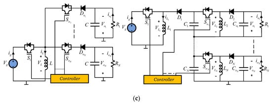
Within SIMO non-isolated with multiple-switch converters, special attention should be paid to Single Input Dual Output (SIDO), Symmetric Outputs DC–DC Converters or Bipolar Output DC–DC Converters, as shown in
Figure 8. Not only because of the interest of its applications, but also because of the different topologies that have been developed [
67,
68,
69,
70,
71,
72,
73,
74,
75,
76,
77].
Figure 8. Single Input Dual Output (SIDO) DC–DC Converters. (
a) Three-level Single-inductor Boost Converter [
69]. (
b) Three-level Two-inductors Boost Converter [
70]. (
c) Dual-output DC–DC Boost Converter [
71]. (
d) Series-combined Boost and Buck–Boost Converter [
72]. (
e) Single-inductor Buck–Boost Converter [
73].
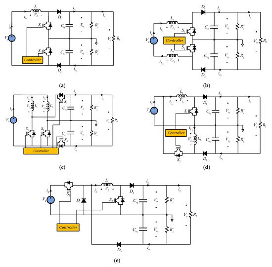
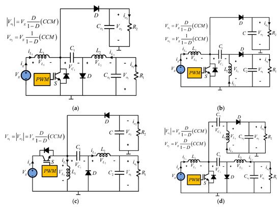
SIMO non-isolated with single-switch converters [
78,
79,
80] try to avoid some of the disadvantages of using multiple controlled switches. They are also based on the combination of SISO structures, using their front end, as shown in
Figure 9 and
Figure 10. In these cases, each output voltage is a function of the duty cycle of the single switch, operation modes (CCM and DCM) and of the combined configuration.
Figure 9. Two-output-type converter combinations. (a) Boost–Ćuk converter combination. (b) Boost–SEPIC converter combination. (c) Buck–Boost–Zeta converter combination. (d) SEPIC–Ćuk converter combination.
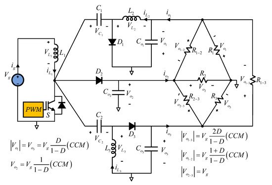
Figure 10. Three-output-type converter combination for six loads.
2.3. MIMO DC–DC Converters Isolated
In the same way, MIMO DC–DC converters for combining various output loads and input sources, they have become an interesting alternative in recent years, especially because they allow the integration of different sources, such as: Rectifiers, Photovoltaic Systems, Fuel Cells, Batteries, Supercapacitors, and, in some cases, Wind Energy Systems. Fundamentally, MIMO converters are implemented according with two structures: sharing a high voltage or low voltage common DC bus; and sharing one or more transformers; or both architectures are also possible.
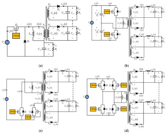
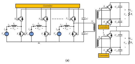
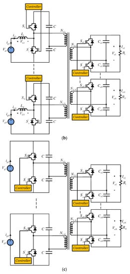
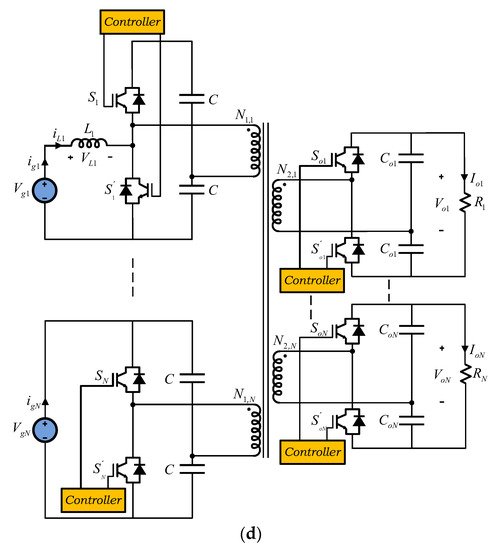
MIMO isolated configurations use a multi-winding transformer to transfer the energy from the primary side to the secondary side and to couple the different sources and loads, with several power switches and centralized or distributed control signals. Several configurations can be derived from Full-Bridge, Half-Bridge Push–Pull Forward and Flyback topologies, and other such as those shown in
Figure 11 [
81,
82]. These converters consist of Boost, Half-Bridge, or the called Boost–Dual-Half-Bridge (BDHB) topologies. In these converters, the conversion ratio and output voltages depend on the control strategy of the power switches, operation modes, and the turns ratio between the transformer windings. Normally, the power switches are controlled by phase-shifted PWM operating at 50% duty cycle, in CCM and DCM.
Figure 11. MIMO isolated. (a) Boost parallel converter. (b) Boost ports converter. (c) Half-Bridge converter. (d) Boost–Half-Bridge converter combination.
2.4. MIMO DC–DC Converters Non-Isolated
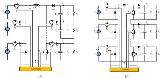
In the same sense, for MIMO transformerless configurations, based on high-voltage or low-voltage common DC bus, two architectures are established: independent and/or integrated DC–DC converters. MIMO non-isolated integrated uses a single conversion stage, simplifying architecture and control, and have been proposed as an alternative to independent architecture connection. These converters are based on single-input single-output configurations such as: Boost, Buck, Buck–Boost, SEPIC, and Ćuk, as well as combinations of these configurations, with common ground [
83,
84,
85] or series connections [
44,
86], as shown in
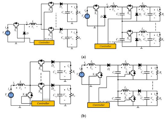
Figure 12.
Figure 12. Non-isolated single-inductor MIMO Converters. (
a) Series outputs [
83,
84,
85]. (
b) Series inputs and series outputs [
44,
86].
Compared with independent architecture connection, integrated MIMO DC–DC converters have the advantage of smaller size, fewer power conversion stages, and lower cost. On the other hand, both the series inputs and the series inputs and series outputs connection, with a single inductor, require a complex control system to avoid cross-regulation problems, and the simultaneous application of different voltages coming from the input sources, which limits the connection of a large number of sources and loads.
The current trend in the development of DC–DC converters with multiple outputs follows general aspects, such as low losses, high-power density, and high efficiency, as well as the development of new architectures and control strategies. Certainly, simple structures with a reduced number of components and power switches will be one of the new trends, especially to reduce the size. However, the incorporation of devices with a Wide Band Gap (WBG), particularly Gallium Nitride (GaN) and Silicon Carbide (SiC), will establish future trends, advantages and disadvantages, in the development and applications of DC–DC converters with multiple outputs.