The majority of sea ice in polar regions can be generalized into two types, (a) level ice that exists as a continuous form, and (b) broken ice that consists of discontinuous ice blocks. Broken ice includes brash ice that normally accumulates in ice channels, sliding ice pieces that form from breaking continuous ice, unconsolidated ice ridges generated by compression between ice floes, and ice floe fields (the most common broken ice condition in the polar region) that appear and evolve with natural processes. In recent years, computational simulation models have increasingly been used for the evaluation of ship operability under broken ice conditions, presenting some challenging issues. A ship’s response in broken ice is divided into two categories: resistance, which relates to the overall ship performance, and local loads, which relates to structural safety.
1. Introduction
1.1. Forms of Broken Ice
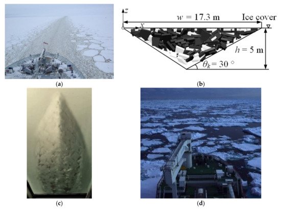
Broken ice is discontinuous, consisting of myriad ice pieces. The ice size, shape, and distribution vary between different types of broken ice, and examples are shown in Figure 1. Brash ice rubbles, Figure 1a, are small compared to other types of broken ice and usually cover ice channels as floating layers with full concentration. The ice rubbles are relatively spherical due to repeating contact with ships and other ice rubbles. Unconsolidated ice ridge rubbles, Figure 1b, share a similar piling feature to brash ice, but the size is larger and the shape is normally not spherical. The ridge keel cross-section can be approximated as a triangle or trapezoid. Sliding ice pieces, Figure 1c, form when ice sheets are broken up by a ship; these have a similar dimension magnitude to ice ridge rubbles. The movement of these ice pieces is restricted by the existence of the intact ice sheets, forming a layer of ice pieces that covers the underwater ship body. Ice floe fields, Figure 1d, are discrete and float on the sea surface. This ice condition is described by its ice concentration, ice diameter, ice thickness, and floe shape.
Figure 1. Various forms of broken ice: (
a) a brash ice channel, (
b) an ice ridge, (
c) sliding ice pieces under an advancing ship during a model-scale test, and (
d) an ice floe field (Figure sources: (
a,
c,
d) are from the first author, (
b) is from
[1]).
1.2. Interaction between a Ship and Broken Ice
During the interaction between a ship and broken ice, kinetic energy is dissipated to push aside, accelerate, submerge, crush, or further break the ice pieces, as well as to compensate for friction. The differences in size and distribution among various types of broken ice result in differences in the energy dissipation process. Given the same thickness and floe shape, the failure of ice by bending and splitting is less dominant when the size of the broken ice is small, but becomes increasingly important for larger ice floes. This affects the dissipation of the ship’s kinetic energy and ultimately determines the interaction force
[2]. In addition to ice failure, hydrodynamics also plays an important role in the interaction process, e.g., through added mass, drag force, and wake
[3]. The fluid flow affects the motion of the ship and the ice before and after the contact and influences the force needed to break the ice
[4].
The main desired outcomes of modelling a ship advancing in broken ice include an increased understanding of ice resistance and ice loads on local structures. Ice resistance is the average summation time of the force of the ice along the hull, which, in surge direction, is equivalent to the ice resistance, and in yaw direction, is the resisting turning moment of the ship. These factors relate to ship performance in areas such as attainable speed, fuel consumption, and maneuvrability in ice. Local ice load refers to the maximum force exerted on a certain part of the ship’s structure, usually impacting one or several frames. This relates to the structural safety of ships, especially for low ice-strengthened merchant ships sailing in floe fields. In this paper, the capabilities of existing simulation methods to estimate resistance and the local ice load are discussed, respectively.
1.3. Simulation of a Ship Advancing in Broken Ice
Unlike formulae used for estimating ship resistance in level ice, analytical formulae proposed for the estimation of broken ice resistance are rare, except those used for sliding ice pieces originating from a breaking ice sheet which have been integrated into the level ice resistance formulae (e.g., submersion resistance as a part of the Lindqvist formula
[5]). Examples of existing formulae for broken ice includes
[6] for a brash ice channel,
[7] for an ice ridge and
[8] for an ice floe field. While analytical formulae for level ice have been widely compared by research institutes and design companies using model and full-scale tests, the accuracy of these formulae for broken ice is not thoroughly confirmed by measurements.
Computational simulation methods offer the opportunity to model the interaction with high fidelity and can potentially provide more accurate results. Due to the discrete nature of broken ice, the Discrete Element Method (DEM) plays a central role in the development of numerical simulation programmes for ships traveling through broken ice. The classical DEM adopts an explicit scheme using rigid blocks and is usually referred to as the Smooth Discrete Element Method (SDEM)
[9], as being applied in
[1][3][10]. The remaining work relevant to broken ice falls into the category of the non-smooth Discrete Element Method (NDEM), which adopts an implicit, non-smooth or event-driven scheme, e.g.,
[11][12][13].
Contact modelling, ice breaking, and the effect of fluid flow are the three main issues associated with the computational modelling of ships in broken ice. The contact is usually modelled as elastic
[14] or viscoelastic
[10], and in some models, there is a plastic limit to mimic ice crushing
[12]. Most of the existing models assume broken ice as rigid
[10], which is relevant for broken ice of small size such as brash ice, ice ridge rubbles, sliding ice pieces, and small-size ice floes, of which a deformable response to a ship is negligible. However, when the ice floe size is sufficiently large, the floes can be broken up by a ship, for which discrete elements need to be incorporated corresponding to possible failure modes
[12]. The DEM and NDEM themselves do not include a fluid solution, i.e., the water surrounding the ship, and the ice requires an additional solution to account for this lack. The fluid effect has been considered using empirical formulae
[11][12], including the Arbitrary Lagrangian-Eulerian framework (ALE)
[14][15], the Lattice Boltzmann Method (LBM), and Computational Fluid Dynamics (CFD)
[3][16].
2. Computational Simulation Methods
2.1. Ice Floe
The ice floe condition is the most common broken ice condition encountered in polar seas because it can form naturally from water as new-frozen ice, or when large ice pieces break up due to heat or ocean waves. Compared to other types of broken ice, the interaction between a ship and ice floes occupies the largest proportion modelled in existing computational work. The size of ice floe varies between different locations and seasons.
The modelling of ship interactions with pancake ice and small ice cakes is relatively straightforward, given that the smaller floes, the less deformable ice behaviour is expected. Particularly, pancake ice has a flat, round appearance
[17], which pairs well with the disk-shaped type of the DEM particles, which is compatible with computational speeds. Huang et al.
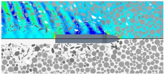
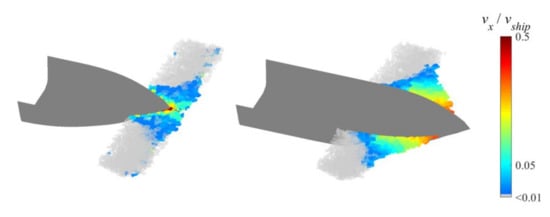
[3][18] presented a coupled CFD+DEM simulation model specifically for pancake ice, as shown in
Figure 2, aiming to calculate ice resistance in such ice fields. In this work, each pancake ice floe is represented as one DEM particle, and the surrounding fluid is modelled by CFD to account for the ship’s wake. The work of Huang et al. has achieved good agreement in terms of resistance using model-scale experiments with synthetic ice, and in terms of fuel consumption, using a series of full-scale measurements on the Northern Sea Route
[18][19][20]. Less than 10% of deviation was achieved in those comparisons.
Figure 2. The CFD+DEM coupled simulation of a ship in a pancake ice field
[3] showing a ship advancing in ice floes with and without the wake effect. It can be seen that the waves can push the floes away from the hull, but when the waves are eliminated, the floes slide closely along the hull and present more contacts.
Most of the other simulation models assume an unbreakable ice floe without specifying the range of the ice floes to which their models apply. Nonetheless, it can be inferred that these models target mainly small ice floes such as pancake ice and ice cakes. Ji et al.
[10] presented another model using a 3D circular disk to model ice floe, aiming to estimate ice resistance and local ice loads. Hydrodynamic forces are simplified as drag and added mass. Their simulation shows that ice resistance varies little when floe size changes, which differs from the results of Huang et al.
[3]. This might be due to the neglect of fluid flow modelling. No detailed validation was carried out for this model. Kim et al.
[21] adopted a simulation setup similar to that of Ji et al., but the simulation was carried out in 2D. Their model was developed for the evaluation of ship maneuverability in floe ice. They also conducted model tests using synthetic ice with up to a 30% concentration to validate the numerical model. Reasonable agreement was shown in terms of speed and turning radius. It is found that the turning radii are smaller in ice than in open water. However, it is unknown whether this model also applies to floe ice of higher concentration.
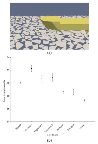
The shape of the ice floe becomes more irregular in the size range of an ice cake, which brings up the need to model ice floes using shapes other than circular disks. Yang et al.
[22] managed to combine multiple common floe shapes in one simulation for the estimation of ice resistance, as shown in
Figure 3. Their model adopts a physical engine for the simulation of contacts and motions, modelling contact force as an impulse. Restitution coefficients are set separately for ship-ice and ice-ice contact to account for the energy loss during collisions. Their work suggests that one NDEM particle can represent these common shapes, and the shape of the ice floe has a clear influence on the computed resistance. Fluid flow is accounted for via added mass and drag force. The results were well compared in terms of mean resistance with model tests using synthetic ice with ice concentrations of up to 60%.
Figure 3. The simulation of a ship in an ice floe field with different shapes and the effect of floe shape on mean ice resistance
[22]: (
a) simulation screenshot; (
b) resistance for different ice shapes.
Table 1 lists the representative models for replicating a ship in floe ice, in terms of a contact force model, an ice floe shape model, a fluid flow model, and an ice cracking model, including a validation method. The models may contain a wider set of elements that are challenging to condense in one table. Using DEM mainly adopted regular floe shapes, i.e., those that can be formulated using mathematical equations. For irregular floe shapes, if the interaction of an abnormal edge is encountered by a ship, it may lack a DEM algorithm to express the contact. It can be observed that only a few models account for local crushing via e.g., a plastic limit
[12][23] or constant pressure
[11], which is essential for the calculation of the local ice load. The viscoelastic contact model is adopted by most classical DEM models, while an impulse is used in models based on a physical engine. Common shapes to model ice floes include a circular disk, polygon, a square, or a rectangle. Only Huang et al.
[3] model the fluid flow extensively using the CFD, while several other models adopt ALE
[14][15][24][25] and LBM
[26]. The other models simply use drag and added mass. The evaluation of bending and splitting failure is enabled using SAMS, as shown by Jou et al. and Sawamura. Compared to other models, SAMS covers the failure of ice, including crushing, bending and splitting under various scenarios, most comprehensively.
Table 1. The summary of models of a ship advancing in floe ice fields.
| |
Contact Model |
Floe Shape |
Fluid Flow |
Cracking |
Validation |
| Huang et al. [3] |
Viscoelastic |
Circular disk |
CFD |
No |
Model test with synthetic ice; full-scale measurement |
| Ji et al. [10] |
Viscoelastic |
Circular disk |
Empirical |
No |
No |
| Kim et al. [21] |
Viscoelastic |
Circular disk |
Empirical |
No |
Model test with synthetic ice |
| Yang et al. [22] |
Impulse |
Polygon |
Empirical |
No |
Model test with synthetic ice |
| DECICE |
Viscoelastic |
Polygon |
Empirical |
No |
Model test with refrigerated ice |
| Polojarvi et al. [23] |
Elastic-viscous-plastic |
Square |
Empirical |
No |
Full-scale measurement |
| Wang and Derradij-Aouat [24] |
Elastic |
Square |
ALE |
No |
Model test with refrigerated ice |
| Kim et al. [25] |
Elastic |
Triangle |
ALE |
No |
Model test with refrigerated ice and synthetic ice |
| Guo et al. [14] |
Elastic |
Square |
ALE |
No |
Model test with synthetic ice |
| Wang et al. [15] |
Elastic |
Square |
ALE |
No |
Model test with synthetic ice |
| Kim et al. [27] |
Elastic |
Polygon |
Empirical |
No |
Model test with refrigerated ice |
| Guo et al. [28] |
Viscoelastic |
Square |
Empirical |
No |
Model test with synthetic ice |
| Janßen et al. [26] |
Impulse |
Random |
LBM |
No |
No |
| GEM |
Plastic |
Polygon |
Empirical |
Yes 1 |
Full-scale measurement |
| SAMS |
Elastic-viscous-plastic |
Polygon |
Empirical |
Yes |
Full-scale measurement |
| Jou et al. [29] |
Viscoelastic |
Rectangle |
No |
Yes |
No |
| Sawamura [13] |
Impulse |
Rectangle |
Empirical |
Yes |
No |
| Liu et al. [30] |
Elastic |
Polygon |
No |
Yes |
No |
1 Not yet published.
2.2. Brash Ice
Brash ice normally exhibits smaller sizes than pancake ice, making allowing it to be modelled as rigid bodies. Nonetheless, pieces of brash ice rubble lie on top of each other, and therefore must be modelled in 3D. Motions of brash ice rubble are largely affected by wake and bow waves. Thus, it can be important to model hydrodynamics numerically unless ship speed is very low. In addition, cohesion may prevail between ice rubbles due to freezing.
Konno
[31] deployed physically based modelling using a physical engine to simulate a ship advancing in a brash ice channel. Ice rubbles are modelled as spherical and cubic particles packed tightly together. The fluid force is accounted for via drag. This revealed the need to set the correct ice-ice frictional coefficient and distribution of ice piece size.
Mucha
[32] presented CFD+DEM modelling of a ship going through a brash ice channel. Ice rubbles are modelled by polyhedral particles. The author tested the sensitivity of resistance on material properties, packing density, degree of coupling, as well as the choice of a reference frame. This work shows the feasibility of CFD+DEM to simulate ship interaction with brash ice, but the results are not compared to physical measurement.
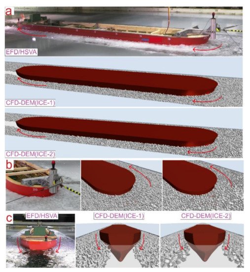
A coupled CFD+DEM approach is adopted by Luo et al.
[16]. Brash ice rubbles are modelled using tetrahedral and irregular polyhedral particles, which are composite particles composed of several basic spherical particles. Interaction between fluid and ice particles is modelled using drag and added mass. Good agreement is achieved between the simulation results and model test results in terms of mean resistance. As shown in
Figure 4, the simulated movement of ice resembles that in the model tests.
Figure 4. The comparison of brash ice movement results from a model test and from a CFD+DEM coupled simulation
[16].
Overall, there are fewer investigations using numerical simulation of ships advancing in brash ice compared to those for ice floes, and the methods are less diverse, mainly being conducted using classical DEM and not accounting for crushing. Existing work has demonstrated the capability of numerical simulation for the qualitative assessment of ice clearing ability, but its validity for quantitative evaluation remains an uncertainty. Additional work is expected to add more insight into issues such as the ice-ice friction, influence of cohesion, effect of fluid flow, role of crushing, and influence of ship speed on ice resistance.
2.3. Ice Ridge
There have been several applications of DEM in ridge keel punch through tests
[33][34], and in ridge interaction with offshore structures
[35], but studies of a ship going through an ice ridge are rare. The simulation by Gong et al.
[1] using the Aalto University in-house DEM code is among the few extensive investigations of ridge resistance via numerical simulation. The scope is limited to an unconsolidated ridge in which ice rubbles are not frozen together. Ridge keels are modelled as triangle and trapezoid shapes, depending on their width and height, as shown in
Figure 5. Their work reveals the influence of ridge width on two resistance components, namely friction force and deformation force. The resistance results obtained from the simulation is shown to have a similar magnitude as that predicted by the empirical formula of Malmberg
[7], but no validation against actual measurement was performed. In the dissertation by Gong
[36], the influence of bow angles on ridge resistance is also investigated. As a conclusion, Gong et al. reported that the unconsolidated ice ridge resistance is proportional to the total ice mass. Another investigation using DEM was conducted by Hisette et al.
[37], where the authors compare simulation results with model test results and demonstrate good agreement on resistance. However, the ice-ice friction coefficient has to be selected and the results can be sensitive to this.
Figure 5. A DEM simulation of a ship penetrating a narrow ice ridge
[36].
2.4. Sliding Ice Pieces from Icebreaking
After a ship breaks level ice, broken ice pieces move downwards and sideways, thereby forming a layer of ice pieces covering a certain extent of the hull. This differs from offshore structures, where ice typically accumulates against the structure. Lindqvist
[5] assumes the covering extent to be 70% as a constant. However, it is reasonable to infer that the actual extent varies between different hull forms. Simulation methods have the potential to distinguish such differences and provide ship-specific solutions. Most of the previous simulation models for level ice breaking involve the simulation of sliding ice pieces, except for those using semi-empirical methods to calculate submersion resistance.
Unlike those for other types of broken ice, the DEM-based simulation has not been applied to simulate a ship’s interaction with sliding ice pieces. Most existing models for a ship going through level ice invests the major effort into the modelling of icebreaking from the level ice sheet, while the subsequent process with broken ice pieces is treated in a simplified way, typically modelled using buoyancy, drag, and added mass, e.g.,
[38][39].
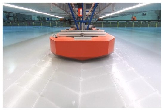
Towing in presawn ice (see
Figure 6) is a standard procedure recommended by ITTC
[40] for the evaluation of resistance arising from ice pieces that have broken away from the level ice sheet. Konno and Mizuki
[41] carried out a dedicated simulation on a ship going through presawn ice using their physically based simulation tool. The simulation reveals some problems with the model in detecting the contact with parallelepiped ice pieces. The comparison with model-scale tests remains qualitative and no validation on resistance has been provided. Another dedicated simulation was presented by Sawamura
[42]. The contacts are modelled as an impulse and the fluid is modelled with drag force. Sawamura presents a 2D and a 3D version of a ship traveling in presawn ice and concludes that the model can describe the process qualitatively. Later, the 2D-version is validated using model tests employing synthetic ice
[43], which shows an underestimation of resistance due to the neglection of hydrodynamics.
Figure 6. A model ship towed through presawn ice at the Aalto ice tank (photo taken by the first author).
3. Conclusions
-
To date, the major computational models created to investigate a ship’s interactions with broken ice have focused on a ship’s interaction with ice floes. There are certain studies on the interaction with brash ice, but ridged ice and sliding ice pieces have received little attention despite their importance in a ships’ ice-going capability. More computational investigations on ridged ice and sliding ice pieces are required to fully understand these processes.
-
Most models of ship interactions with ice floes are created for resistance estimation, while only a few works have addressed local ice loads. More future research is suggested on the estimation of local loads, which serves as a structural safety evaluation, especially in the context of merchant ships traveling through the Arctic region.
-
Most models assume ice to be unbreakable, making them suitable for modelling broken ice only up to a certain size. Introducing a cracking mechanism can widen the range of applicability of the existing models. For example, this could be achieved by using clumped DEM particles.
-
The role of crushing during a ship’s interaction with small-sized broken ice is recommended for investigation in future work. Many models simplify this process by defining it as elastic contacts due to the complexity of modelling, but the effect of small ice-piece crushing on ice resistance estimations has yet to be thoroughly clarified.
-
The majority of existing models simplify the hydrodynamic force as drag and added mass, which deviates the estimation, especially when ship wakes play a big role in the movement of broken ice. Coupling between DEM and CFD offers good potential for dealing with the factor of broken ice interaction with ships. CFD gives good indications of the wake variation versus the ship speed, which is what the ship-associated flow mainly depends on. With a widespread reduction of the extent, thickness, and compactness of sea ice, hydrodynamics is expected to be increasingly important for studying ship-ice interactions. Therefore, further development and validation of CFD-based methods are particularly recommended.
 +1 credit