 +1 credit
| Version | Summary | Created by | Modification | Content Size | Created at | Operation |
|---|---|---|---|---|---|---|
| 1 | ANDREI STAN | + 2145 word(s) | 2145 | 2022-02-15 11:54:08 | | | |
| 2 | Camila Xu | -8 word(s) | 2137 | 2022-03-07 11:14:38 | | | | |
| 3 | Camila Xu | -7 word(s) | 2138 | 2022-03-07 11:24:33 | | | | |
| 4 | Camila Xu | -7 word(s) | 2138 | 2022-03-07 11:25:05 | | | | |
| 5 | Camila Xu | Meta information modification | 2138 | 2022-03-07 11:26:40 | | | | |
| 6 | Camila Xu | Meta information modification | 2138 | 2022-03-07 11:27:30 | | |
Video Upload Options
Two main high voltage direct current (HVDC) technologies: line-commutated converters (LCC), also known as current-source converters (CSC) using thyristors, and voltage-source converters (VSC)-HVDC, using IGBT transistors, both are suitable for a wide range of applications.
1. Introduction
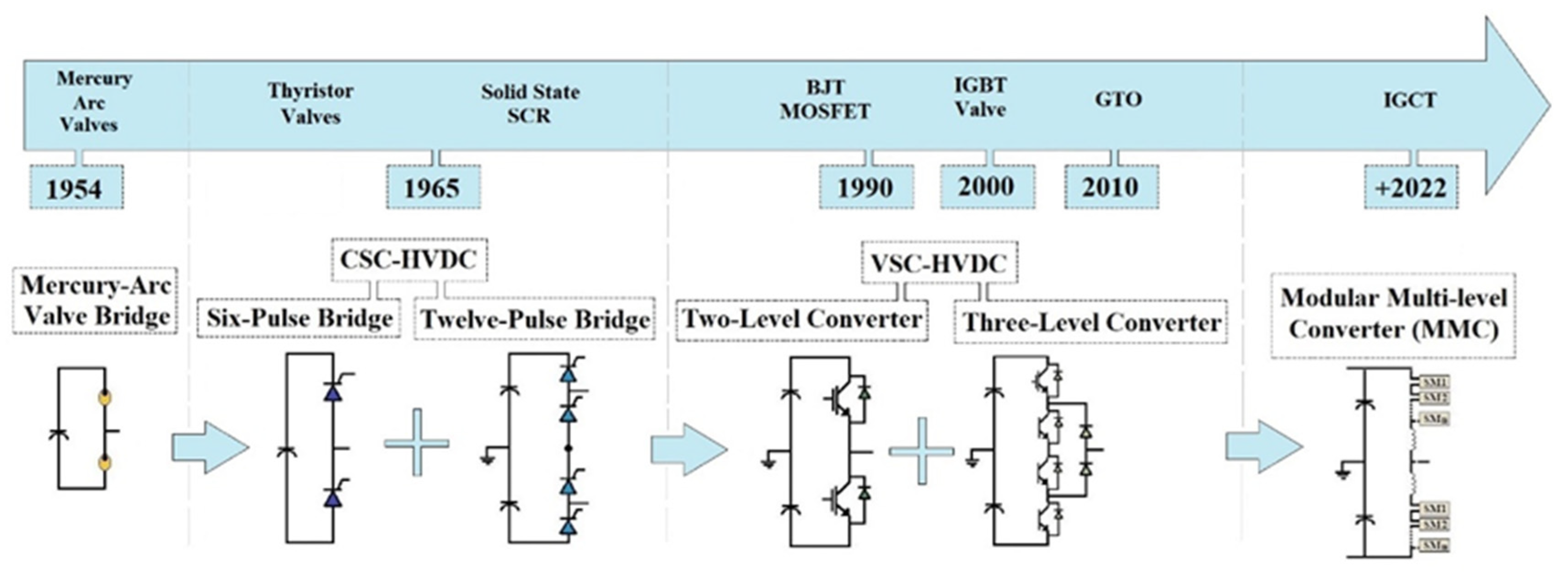 Figure 1. HVDC technological evolution.
2. Main Areas of HVDC Applications
- -Long-distance power transmission lines;
- -Submarine cable transmission (connections with lengths greater than 50 km usually used for offshore wind power plants power evacuation);
- -Interconnection of systems that operate asynchronously;
- -Multi-terminal HVDC systems.
3. Types of HVDC Links Topology
3.1. Monopolar Links
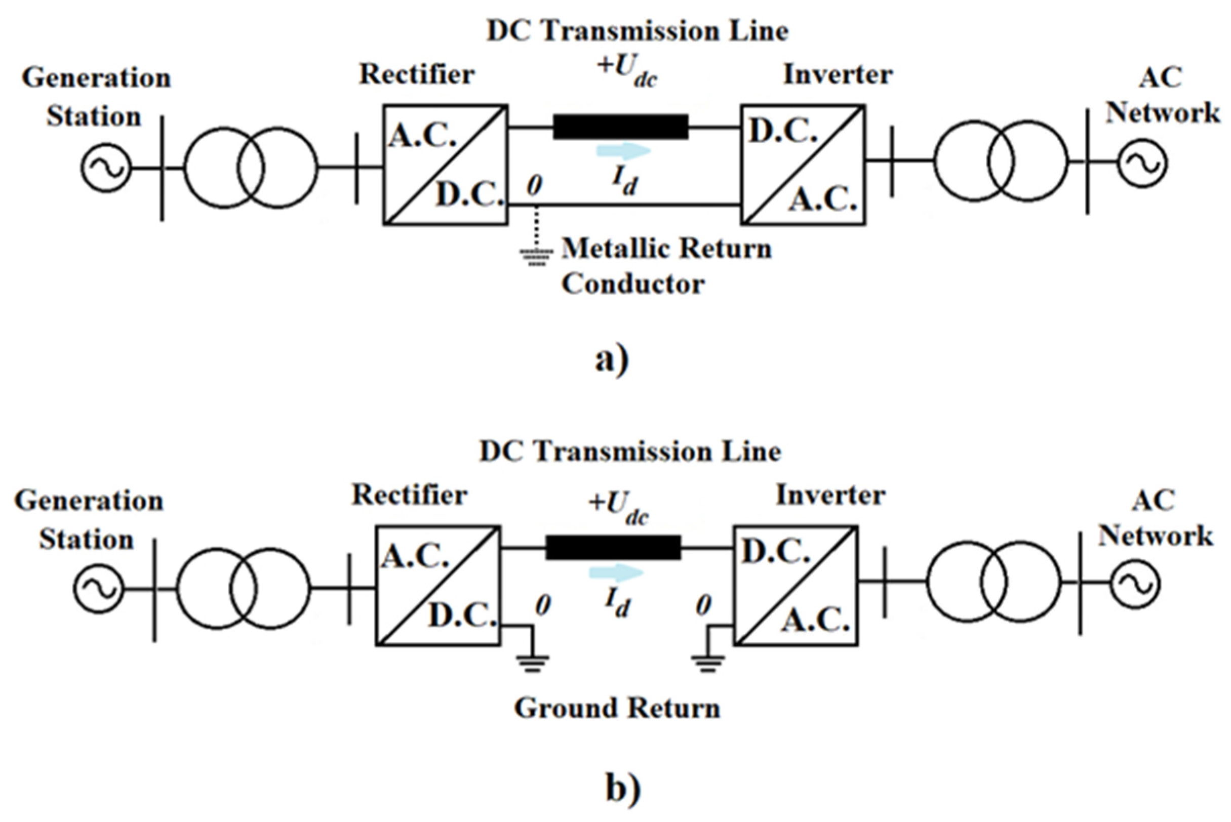 Figure 2. HVDC monopolar links: (a) metallic return conductor, (b) ground return.
3.2. Bipolar Links
-
Bipolar Link with Ground Return Path
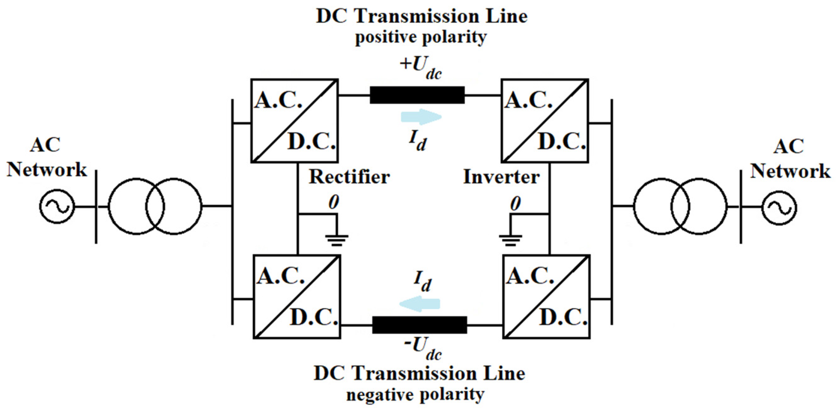 Figure 3. HVDC bipolar links ground return.
-
Bipolar Link with Dedicated Metallic Return Path
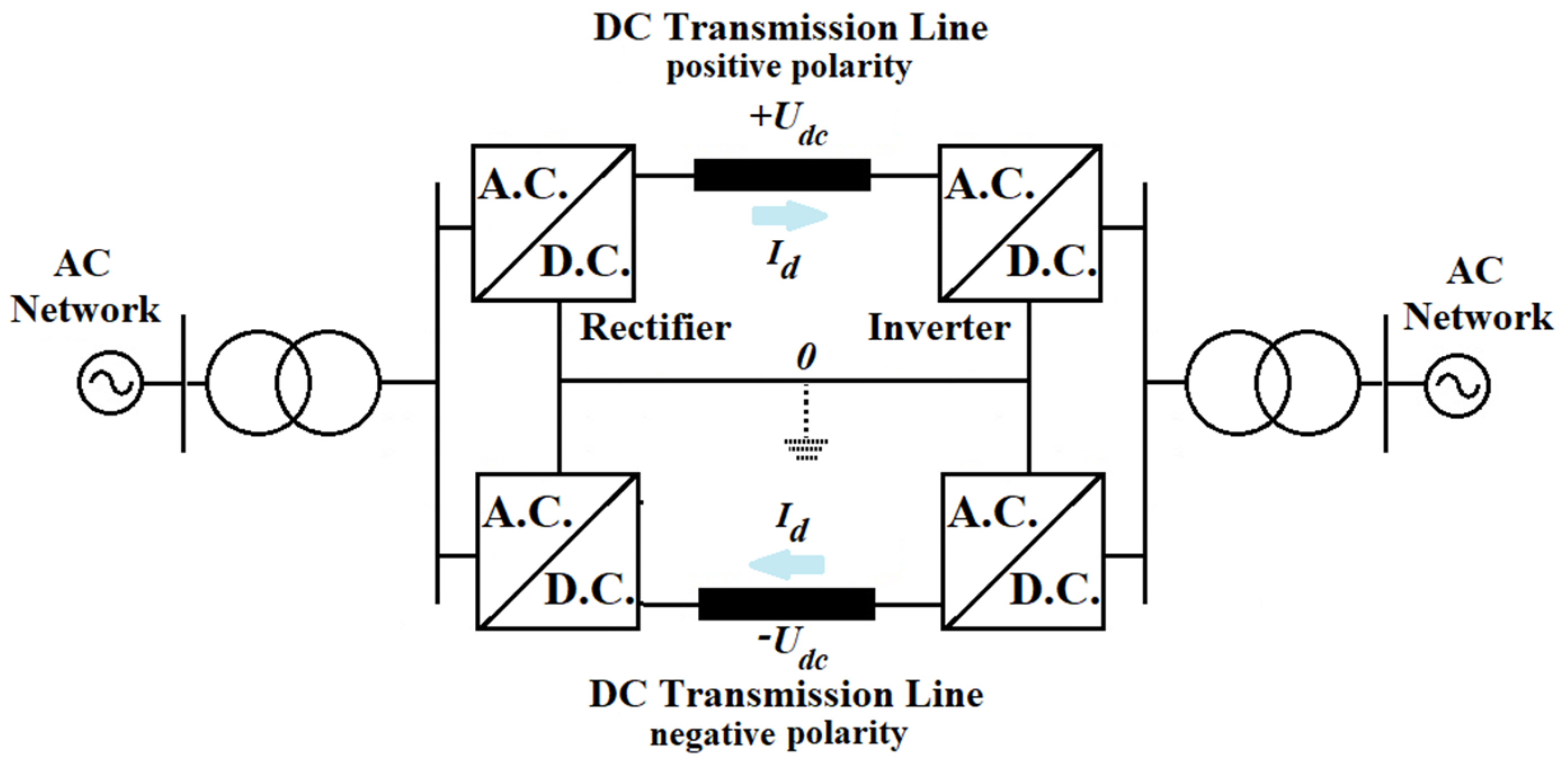 Figure 4. HVDC bipolar links metallic return conductor.
3.3. Back-to-Back Links
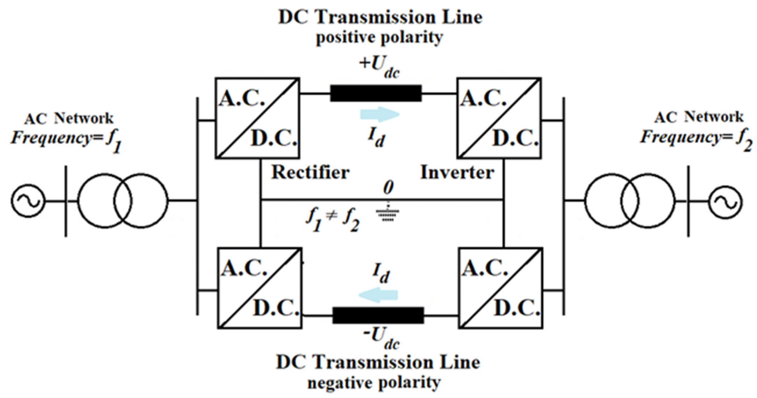 Figure 5. HVDC back-to-back links.
3.4. Homopolar Links
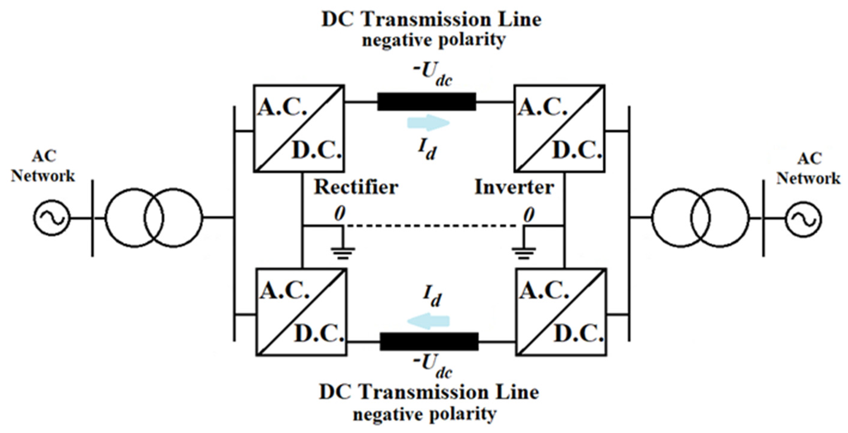 Figure 6. HVDC homopolar link.
4. Main Components of HVDC Substations and Control Strategies
4.1. Main components of HVDC substations
The AC network is connected to the HVDC converter station by a converter busbar, represented by one or more typical AC busbars, to which the converter is connected [15][16].
In Figure 7, the basic structure of an HVDC substation in the case of CSC-HVDC is presented, and in Figure 8 the basic structure of VSC-HVDC is presented [16][17][18][19][20].
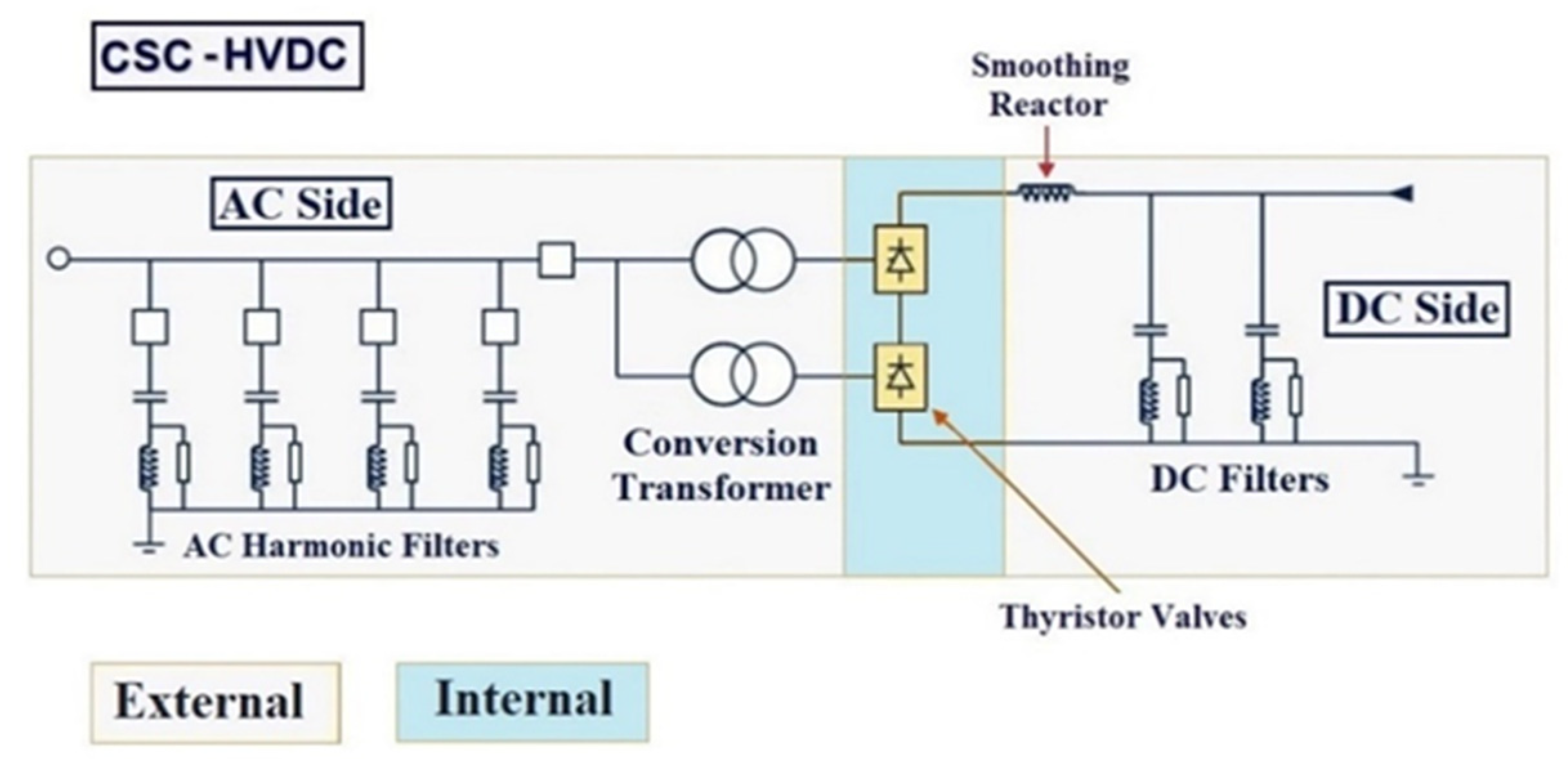 Figure 7. CSC-HVDC main components.
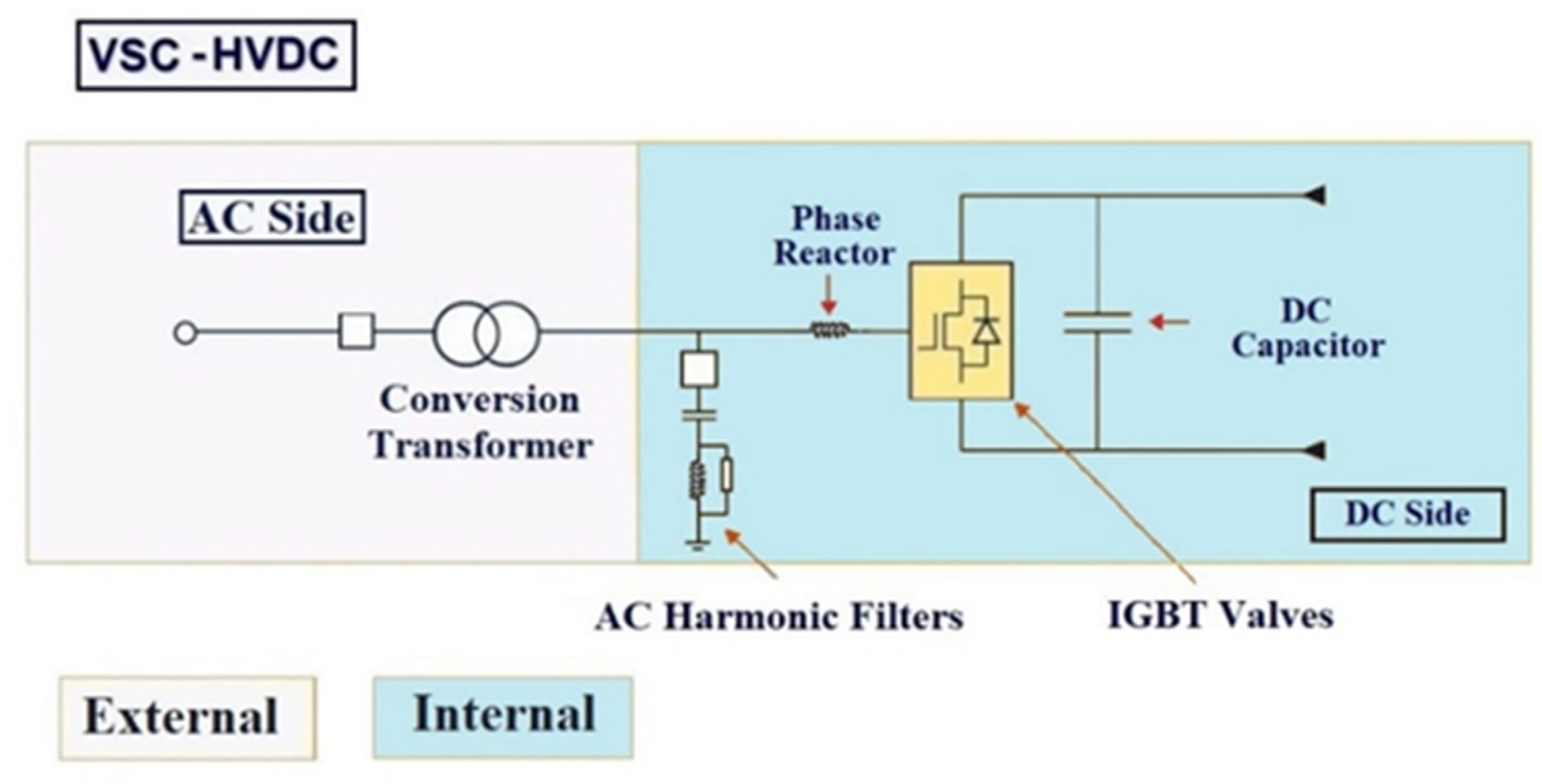 Figure 8. VSC-HVDC main components.
- Converter Valves (IGBT or Thyristor);
- Conversion power transformers;
- Measuring instruments AC (voltage/current transformers);
- AC harmonic filters and AC shunt capacitors.
- DC-OHL/UGC (usually XLPE cable in case of VSC technology);
- DC harmonic filters; phase reactor (VSC-HVDC);
- DC capacitor (VSC-HVDC);
- Smoothing reactor;
- Measuring instruments DC (voltage/current transformers);
- DC switchgear (disconnector switchers/circuit breakers);
4.2. CSC-HVDC Control Methods and Strategies
One of the main characteristics of HVDC technology is the ability to control the active power flow, both in terms of magnitude and direction. The flow of the active power can be controlled either by changing the DC voltage Ud or the DC current Id associated with the DC link [21][22][23].
Figure 9 shows the operating modes of the LCC converter either as an inverter or rectifier.
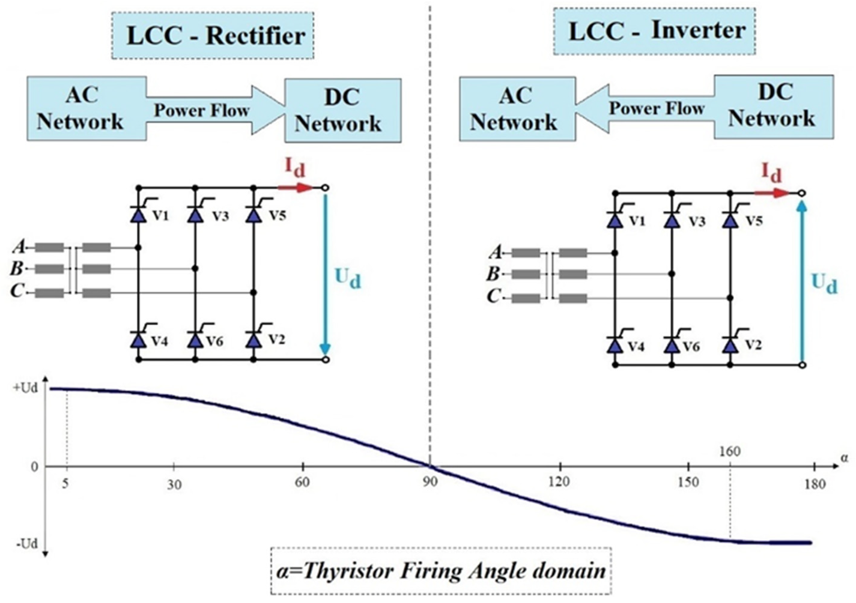 Figure 9. CSC-HVDC Converter operating modes.
4.3. VSC-HVDC Control Methods and Strategies
The main control methods used in VSC-HVDC systems are the “power angle” control strategy and “vector current” control strategy [24].
4.3.1 “Power Angle” Control Strategy
“Power angle” control, also called “voltage angle”, is probably the most direct method possible for controlling VSC-HVDC links.
The basic principle of the “power angle” control method is the following: the active power is controlled by changing the phase angle θ of the voltage associated with the VSC-HVDC connection, while the reactive power is controlled by changing the magnitude of the voltage of the VSC-HVDC connection [24][25][26].
A simplified control scheme usually used for this strategy is presented in Figure 10 [24][25][26].
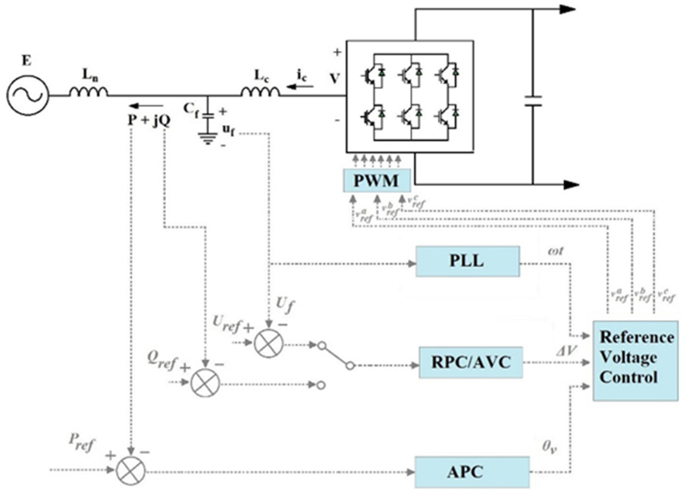 Figure 10. VSC-HVDC “power angle” control strategy.
In order to produce the tri-phase alternating voltage, the VSC-type device needs the following three control variables: magnitude, the phase angle, and the AC frequency. By using the “power angle” control method, the three variables are given by three different control loops, plus an additional synchronization loop, as follows [24][25][26].
- RPC (reactive power control)
- AVC (active voltage control)
- APC (active power control)
- PLL (phase-locked loop)
4.3.2 “Vector Current” Control Strategy
The “vector-current” control strategy consists of controlling the current associated with the VSC–HVDC converter station. It was first used in variable speed drives, where the VSC is connected to an AC motor [24][25][26].
In the case of VSC-HVDC-type connections, the “vector-current” control strategy consists of the independent control of the active and reactive power by means of the following cascaded loops: external control loops and the inner current control loop.
Compared to the “power angle”-type control method, which uses as input quantities ΔV, θv, and ωt, by means of which the three-phase reference voltages of the VSC-HVDC converter are generated, the “vector current” control method works in a similar fashion, using as inputs the reference voltages in axis d and q are as follows: vrefd, vrefq, and ωt [24][25][26] (Figure 11).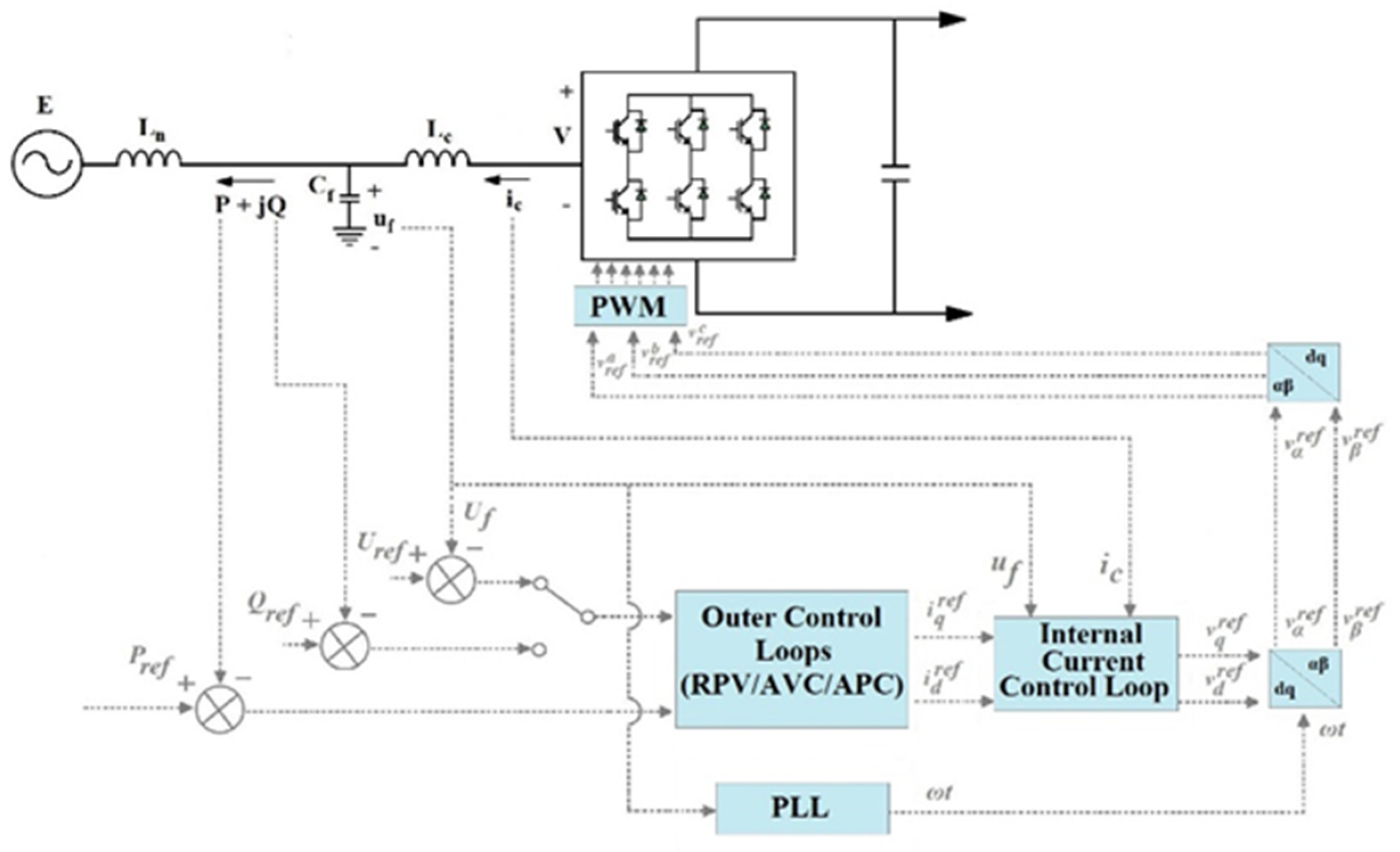
Figure 11. VSC-HVDC “vector current” control strategy.
5. Key Challenges Arising from the Use of HVDC Systems
The use of HVDC technology creates several issues, which need to be properly addressed:
- DC Circuit Breaker
- Reliability and Maintenance of HVDC Converter Substations
- Multi-Terminal HVDC System Operation
5.1. DC Circuit Breaker Solutions
The main issue regarding the implementation of circuit breakers (CB) in DC circuits is that there is no natural passage of fault current through zero, as in the case of classical AC systems. In DC circuits, the fault current can be brought to zero only by applying a higher counter voltage (Vb) than the operating voltage of the system [27].
A second problem is the need to dissipate a large amount of energy stored in the inductor of the DC line.
In order to solve those issues, a typical DC breaker arrangement is equipped with two additional circuits besides the main circuit breaker, an energy-absorbing circuit, and a commutating circuit [28][29].
The main types of DC circuit breakers are the following:
- Electromechanical Circuit Breaker;
- Solid-State Circuit Breakers (SSCB);
- Hybrid Circuit Breaker.
5.2. Reliability and Maintenance of HVDC Converter Substations
Given the rapid advancement of power electronics, a growing number of HVDC projects have been installed across the world. Their reliability and maintenance strategies have a direct influence on the system’s service security and, as a result, have a significant impact on network operation [30].
Recently, the emphasis has been on monitoring the operation of the converters in order to maintain proper operation. But due to the complexity of power converter structures and their degradation mechanisms, interpreting the information obtained by this technique (monitoring) is difficult, especially for non-experts [31][32].
6. Future Trends and Applications of HVDC Transmission Systems
The main future trends and applications of HVDC technology are the following:
- Modular Multilevel Converter (MMC) HVDC [33][34][35] [36];
- Cascaded Two-Level (CTL) HVDC [37][38][39][40];
- Classical Hybrid VSC-CSC HVDC Links [41][42][43][44];
- New VSC- HVDC Bipolar Topologies [45];
- Flexible LCC Converter [45];
- Use of VSC-HVDC for Voltage Stabilization and Transient Stabilization [46].
7. Conclusions
The most used applications of HVDC technologies are summarized as the following: long-distance bulk power transmission, submarine cable transmission, asynchronous ties, offshore wind power plant transmission, and multi-terminal HVDC systems;
At the moment, the main types of HVDC topologies used are the monopolar link, bipolar link (both with metallic return conductor or ground return path), back-to-back link, and homopolar link;
The primary components of the HVDC converter stations are presented for both VSC technology (particularly the use of phase reactor and DC capacitors) and CSC technology (particularly the use of DC and AC filters);
The main control strategies and U-I characteristics used for CSC-HVDC control are summarized (CCR, CCI, CIA, and CEA). Also, the main strategies for VSC-HVDC (power angle and vector control strategies) are presented with the associated active and reactive power control loops and the PLL loop (phase-locked loop) implementation;
Furthermore, the following series of key challenges arising from the use of HVDC technologies are discussed: DC circuit breaker solutions (the main types of existing circuit breakers are as follows: electromechanical, solid-state, and hybrid circuit breakers are presented), reliability and maintenance of HVDC converter substation, multi-terminal operation;
The entry also takes a look at the future trends and applications of HVDC technologies such as MMC, CTL converters, hybrid implementation of HVDC links, new types of bipolar topologies, and network stability improvement applications of HVDC technology.
References
- Peake, O. The history of high voltage direct current transmission. Aust. J. Multi-Discip. Eng. 2010, 8, 47–55.
- Asplund, G.; Carlsson, L.; Tollerz, O. 50 years HVDC Part I, ABB – from pioneer to world leader. ABB Rev. 2003, 4, 6–13.
- Haglöf, L. HVDC Veterans’ Presentations—The History of HVDC Part 1: The Mercury Arc Valve Era; HVDC 50 years: Presentation at the Gotland seminar, 6 May 2004; ABB: Zürich, Switzerland, 2004.
- Melhem, Z. Electricity Transmission, Distribution and Storage Systems; Woodhead Pub: Oxford, UK, 2013.
- Okba, M.H.; Saied, M.H.; Mostafa, M.Z.; Abdel Moneim, T.M. High voltage direct current transmission—A review, part I. In Proceedings of the 2012 IEEE Energytech, Cleveland, OH, USA, 29–31 May 2012; pp. 1–7.
- Flisberg, G.; Carlsson, C.; Moni, R.; Boveri, A. Global Trends in Bulk Power Transmission; ABB Group: Ludvika, Sweden, 2009.
- Bahrman, M.; Johnson, B. The ABCs of HVDC transmission technologies. IEEE Power Energy Mag. 2007, 5, 32–44.
- Chitode, J.S. Power Electronics, 4th ed.; Technical Publications: Maharashtra, India, 2009.
- Kuruganty, S. HVDC transmission system models for power system reliability evaluation. In Proceedings of the IEEE WESCANEX 95: Communications, Power, and Computing Conference, Winnipeg, MB, Canada, 15–16 May 1995; Volume 2, pp. 501–507.
- Billinton, R.; Fotuhi-Firuzabad, M.; Faried, S.O.; Aboreshaid, S. Composite system reliability evaluation incorporating an HVDC link and a static synchronous series compensator. In Proceedings of the IEEE CCECE2002: Canadian Conference on Electrical and Computer Engineering (Cat. No. 02CH37373), Winnipeg, MB, Canada, 12–15 May 2002; Volume 1, pp. 42–47.
- Singh, M.D.; Khanchandai, K.B. Power Electronics, 2nd ed.; Tata McGraw-Hill Publishing Company Limited: New York, NY, USA, 2008.
- Zhang, C. UHV Transmission Technology; Edited by The China Electric Power Research Institute; Elsevier Science: Amsterdam, The Netherlands, 2018.
- Sivanagaraju, S.; Satyanarayana, S. Electric Power Transmission and Distribution; Dorling Kindersley: New Delhi, India, 2012.
- Sood, V. HVDC and FACTS Controllers: Applications of Static Converters in Power Systems; Kluwer Academic Publishers: Amsterdam, The Netherlands, 2004.
- Retzmann, D.; Siemens, A.G. HVDC Station Layout, Equipment LCC & VSC and Integration of Renewables Using HVDC; Cigré Tutorial; CIGRE: Paris, France, 2012.
- Alstom, H.V.D.C. HVDC for Beginners and Beyond; Alstom: Saint-Ouen, France, 2010.
- Csutar, V.G.; Kallikuppa, S.; Charles, L. Introduction to HVDC Architecture and Solutions for Control and Protection; Texas Instruments: Dallas, TX, USA, 2020.
- Jonsson, T. High Power Electronics for HVDC Power Transmission; TSTE19 Power Electronics Lecture 14; ABB Grid Systems: Västerås, Sweden, 2015.
- Roy, R.; Amin, M. A paper of determination of controlling characteristics of the monopolar HVDC system. Int. J. Hybrid Inf. Technol. 2014, 7, 105–120.
- Brand, L.; de Silva, R.; Bebbington, E.; Chilukuri, K. Grid West Project HVDC Technology Review; EirGrid, PSC Specialist Consultants for Electricity Industry: Dublin, Ireland, 2014.
- Larruskain, D.M.; Zamora, I.; Mazón, A.; Abarrategui, O.; Monasterio, J. Transmission and distribution networks: AC versus DC. In Proceedings of the 9th Spanish Portuguese Congress on Electrical Engineering, Marbella, Spain, 30 June–2 July 2005.
- Setréus, J.; Bertling Tjernberg, L. Introduction to HVDC technology for reliable electrical power systems. In Proceedings of the 10th International Conference on Probablistic Methods Applied to Power Systems, Rincon, Puerto Rico, 25–29 May 2008; pp. 1–8.
- Eremia, M.; Liu, C.-C.; Edris, A.-A. Advanced Solutions in Power Systems: HVDC, FACTS, and Artificial Intelligence; IEEE Press: Piscatway, NJ, USA; Wiley: Hoboken, NJ, USA, 2016.
- Zhang, L. Modeling and Control of VSC–HVDC Links Connected to Weak AC Systems. Ph.D. Thesis, Royal Institute of Technology, School of Electrical Engineering Electrical Machines and Power Electronics, Stockholm, Sweden, 2010.
- Zheng, X.; Li, Y.; Liu, Z.; Wang, C. Steady-state control strategy of VSC-HVDC transmission system based on full-order terminal sliding mode control method. J. Eng. 2019, 2019, 987–990.
- Stan, A.; Stroe, D.; da Silva, R. Control strategies for VSC-based HVDC transmission system. In Proceedings of the 2011 IEEE International Symposium on Industrial Electronics, Gdansk, Poland, 27–30 June 2011; pp. 1387–1392.
- Muriuki, J.K.; Muriithi, C.M.; Ngoo, L.; Nyakoe, G. Review of HVDC circuit breakers topologies. IOSR J. Electr. Electron. Eng. 2017, 12, 109–117.
- Padiyar, K. HVDC Power Transmission Systems—Technology and System Interactions, 1st ed.; New Age International Limited: New Delhi, India, 2005.
- Nakanishi, K. Switching Phenomena in High-Voltage Circuit Breakers, 1st ed.; Marcel Dekker, Inc.: New York, NY, USA, 1991.
- Khorasaninejad, M.; Radmehr, M.; Firouzi, M.; Koochaki, A. Application of a resistive mutual-inductance fault current limiter in VSC-based HVDC system. Int. J. Electr. Power Energy Syst. 2022, 134, 107388.
- Cochrane, J.; Emerson, M.; Donahue, J.; Wolf, G. A survey of HVDC operating and maintenance practices and their impact on reliability and performance. IEEE Trans. Power Deliv. 1996, 11, 514–518.
- Georgiana, I.; Costinas, S.; Stan, A. Trends to increase the life cycle of a substation in context of smart grid; Power up our Future; In Proceedings of the 10th International Conference on Energy and Environment CIEM 2021, Bucharest, Romania, 14–15 October 2021.
- Beddard, A.; Barnes, M. Modelling of MMC-HVDC systems—An overview. Energy Procedia 2015, 80, 201–212.
- Gomis-Bellmunt, O.; Liang, J.; Hertem, D. HVDC Grids: For Offshore and Supergrid of the Future; John Wiley & Sons Inc.: Hoboken, NJ, USA, 2016.
- Zhang, B.; Zhao, C.; Guo, C.; Xiao, X.; Zhou, L. Controller architecture design for MMC-HVDC. Adv. Electr. Comput. Eng. 2014, 14, 9–16.
- Sharifabadi, K.; Harnefors, L.; Nee, H.; Norrga, S.; Teodorescu, R. Design, Control, and Application of Modular Multilevel Converters for HVDC Transmission Systems, 1st ed.; Wiley: Hoboken, NJ, USA; IEEE Press: Piscatway, NJ, USA, 2016.
- Jacobson, B.; Karlsson, P.; Asplund, G.; Harnefors, L.; Jonsson, T. VSC-HVDC Transmission with Cascaded Two-Level Converters; ABB Sweden: Zürich, Switzerland; CIGRE: Paris, France, 2010.
- Acha, E.; Jaén, A.; Kazemtabrizi, B.; Castro, L.; Roncero-Sánchez, P. VSC-FACTS-HVDC: Analysis, Modelling and Simulation in Power Grids, 1st ed.; Wiley: Hoboken, NJ, USA, 2019.
- Li, B.; Li, J. Probabilistic sizing of a low-carbon emission power system considering HVDC transmission and microgrid clusters. Appl. Energy 2021, 304, 117760.
- Echeverría, J.; Kouro, S.; Pérez, M.; Abu-rub, H. Multi-modular cascaded DC-DC converter for HVDC grid connection of large-scale photovoltaic power systems. In Proceedings of the IECON 2013—39th Annual Conference of the IEEE Industrial Electronics Society, Vienna, Austria, 10–13 November 2013; pp. 6999–7005.
- Cheah-Mane, M.; Song, J.; Ferrer-San-Jose, R.; Prieto-Araujo, E.; Gomis-Bellmunt, O. Analysis of hybrid LCC-VSC HVDC transmission system configurations. In Proceedings of the 15th IET International Conference on AC and DC Power Transmission (ACDC 2019), Coventry, UK, 5–7 February 2019; pp. 1–6.
- Sun, P.; Wickramasinghe, H.R.; Konstantinou, G. Hybrid LCC-AAC HVDC transmission system. Electr. Power Syst. Res. 2021, 192, 106910.
- Xiao, H.; Sun, K.; Pan, J.; Li, Y.; Liu, Y. Review of hybrid HVDC systems combining line communicated converter and voltage source converter. Int. J. Electr. Power Energy Syst. 2021, 129, 106713.
- Perez-Molina, M.J.; Larruskain, D.M.; Lopez, P.E.; Buigues, G.; Valverde, V. Review of protection systems for multi-terminal high voltage direct current grids. Renew. Sustain. Energy Rev. 2021, 144, 111037.
- Wang, M.; An, T.; Ergun, H.; Lan, Y.; Andersen, B.; Szechtman, M.; Leterme, W.; Beerten, J.; Van Hertem, D. Review and outlook of HVDC grids as backbone of the transmission system. CSEE J. Power Energy Syst. 2021, 7, 797–810.
- Nishioka, A.; Alvarez, F.; Omori, T. Global Innovation Report—Global Rise of HVDC and Its Background. Hitachi Rev. 2021, 69, 462–463.

