Two main high voltage direct current (HVDC) technologies: line-commutated converters (LCC), also known as current-source converters (CSC) using thyristors, and voltage-source converters (VSC)-HVDC, using IGBT transistors, both are suitable for a wide range of applications.
- applications of HVDC transmission systems
- control strategies
- technology
1. Introduction
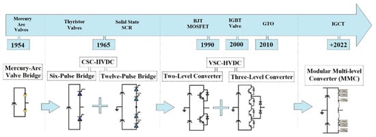
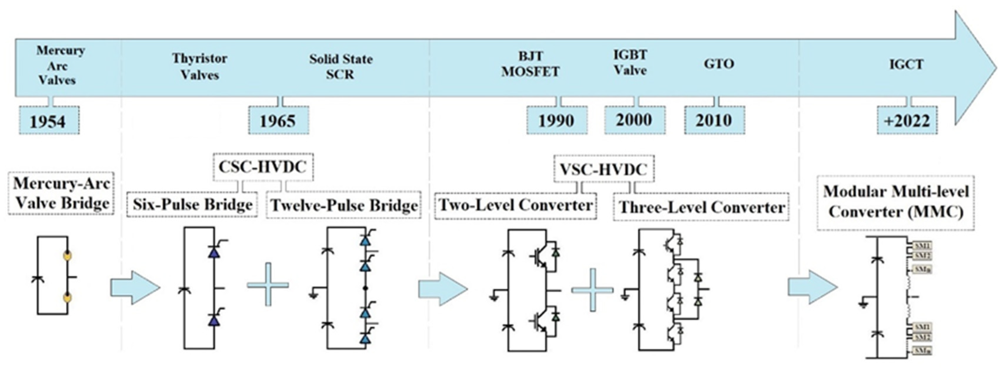 Figure 1. HVDC technological evolution.
2. Main Areas of HVDC Applications
HVDC technology has gradually gained worldwide popularity. The use of DC links, to the detriment of AC classical solutions, is justified by several advantages (e.g., active power control, higher transfer capacities, no reactive power, longer transmission possible lengths, and lower active power losses) in some cases being the only feasible technology [6,7]. The main areas of HVDC applications include:- -Long-distance power transmission lines;
- -Submarine cable transmission (connections with lengths greater than 50 km usually used for offshore wind power plants power evacuation);
- -Interconnection of systems that operate asynchronously;
- -Multi-terminal HVDC systems.
3. Types of HVDC Links Topology
3.1. Monopolar Links
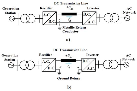
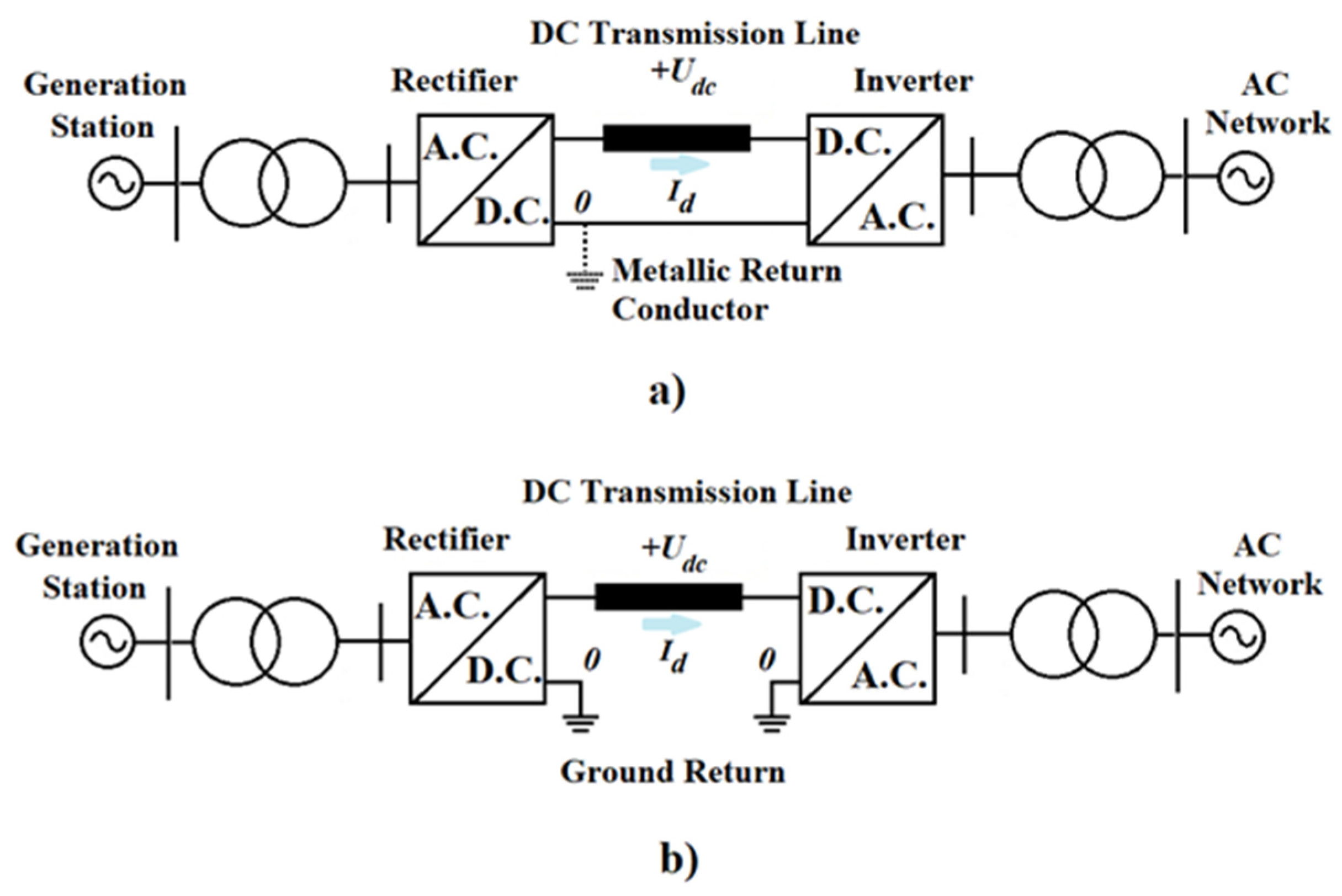 Figure 32. HVDC monopolar links: (a) metallic return conductor, (b) ground return.
3.2. Bipolar Links
- Bipolar Link with Ground Return Path
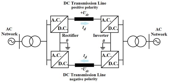
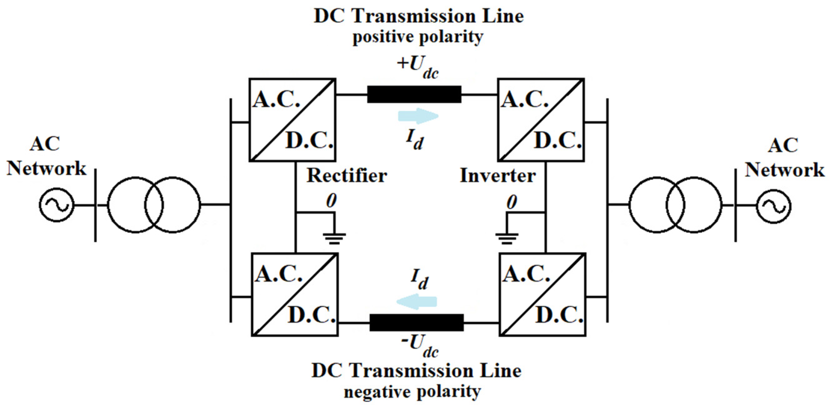 Figure 43. HVDC bipolar links ground return.
- Bipolar Link with Dedicated Metallic Return Path
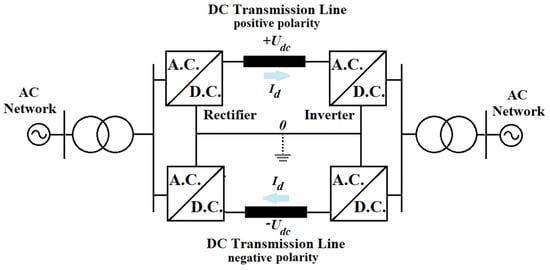
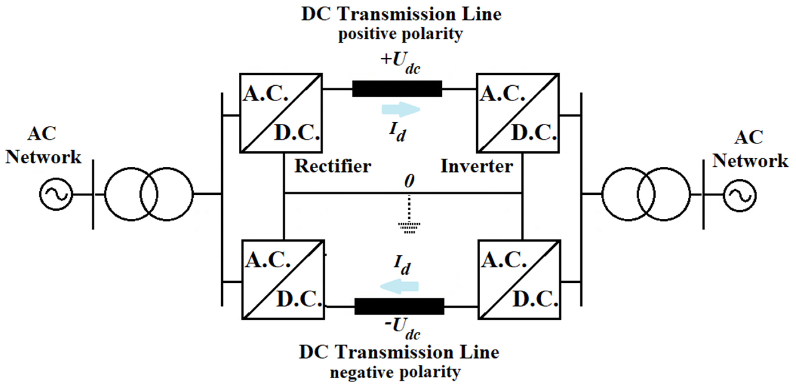 Figure 54. HVDC bipolar links metallic return conductor.
3.3. Back-to-Back Links
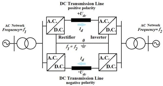
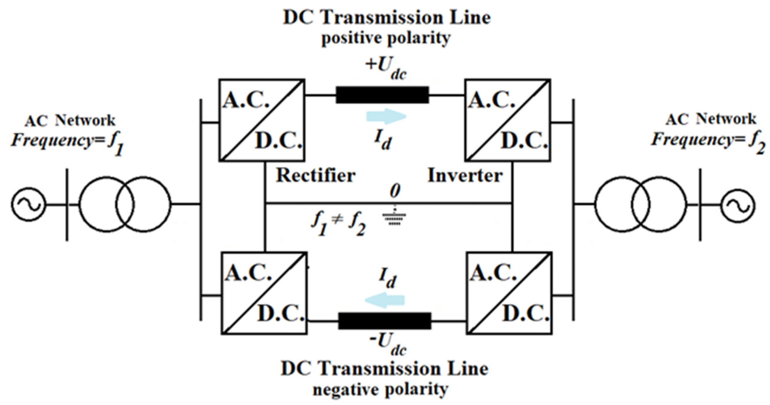 Figure 65. HVDC back-to-back links.
3.4. Homopolar Links
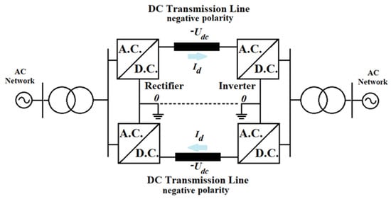
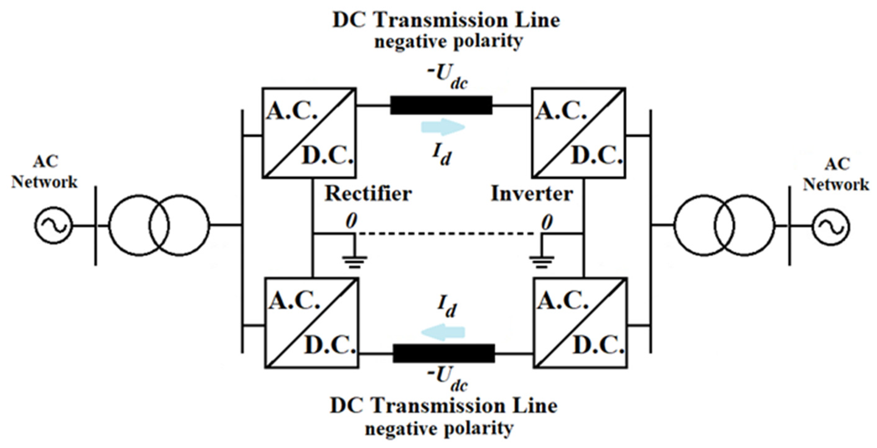 Figure 76. HVDC homopolar link.
4. Main Components of HVDC Substations and Control Strategies
4.1. Main components of HVDC substations
The AC network is connected to the HVDC converter station by a converter busbar, represented by one or more typical AC busbars, to which the converter is connected [30,31].
In Figure 87, the basic structure of an HVDC substation in the case of CSC-HVDC is presented, and in Figure 98 the basic structure of VSC-HVDC is presented [31,32,33,34,35].
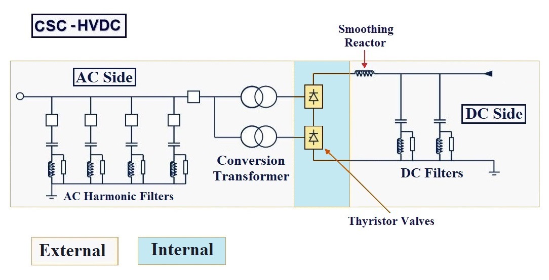
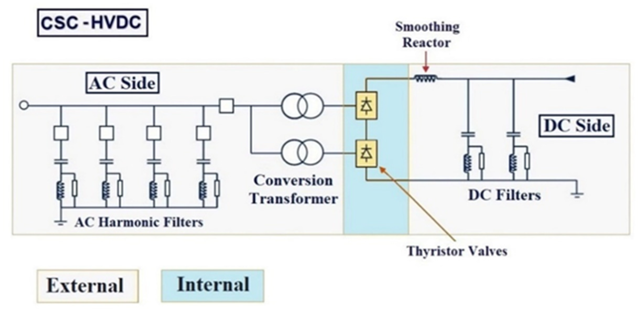 Figure 87. CSC-HVDC main components.
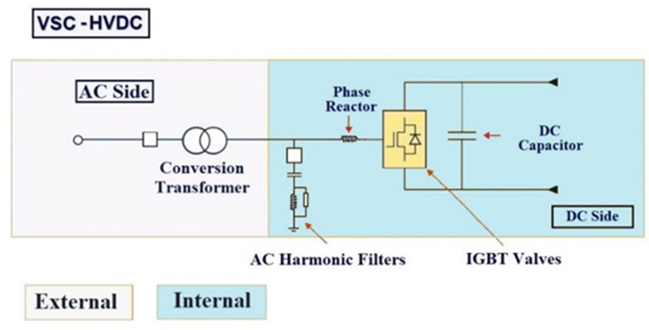 Figure 98. VSC-HVDC main components.
- Converter Valves (IGBT or Thyristor);
- Conversion power transformers;
- Measuring instruments AC (voltage/current transformers);
- AC harmonic filters and AC shunt capacitors.
- DC-OHL/UGC (usually XLPE cable in case of VSC technology);
- DC harmonic filters; phase reactor (VSC-HVDC);
- DC capacitor (VSC-HVDC);
- Smoothing reactor;
- Measuring instruments DC (voltage/current transformers);
- DC switchgear (disconnector switchers/circuit breakers);
4.2. CSC-HVDC Control Methods and Strategies
One of the main characteristics of HVDC technology is the ability to control the active power flow, both in terms of magnitude and direction. The flow of the active power can be controlled either by changing the DC voltage Ud or the DC current Id associated with the DC link [36,37,38].
Figure 109 shows the operating modes of the LCC converter either as an inverter or rectifier.
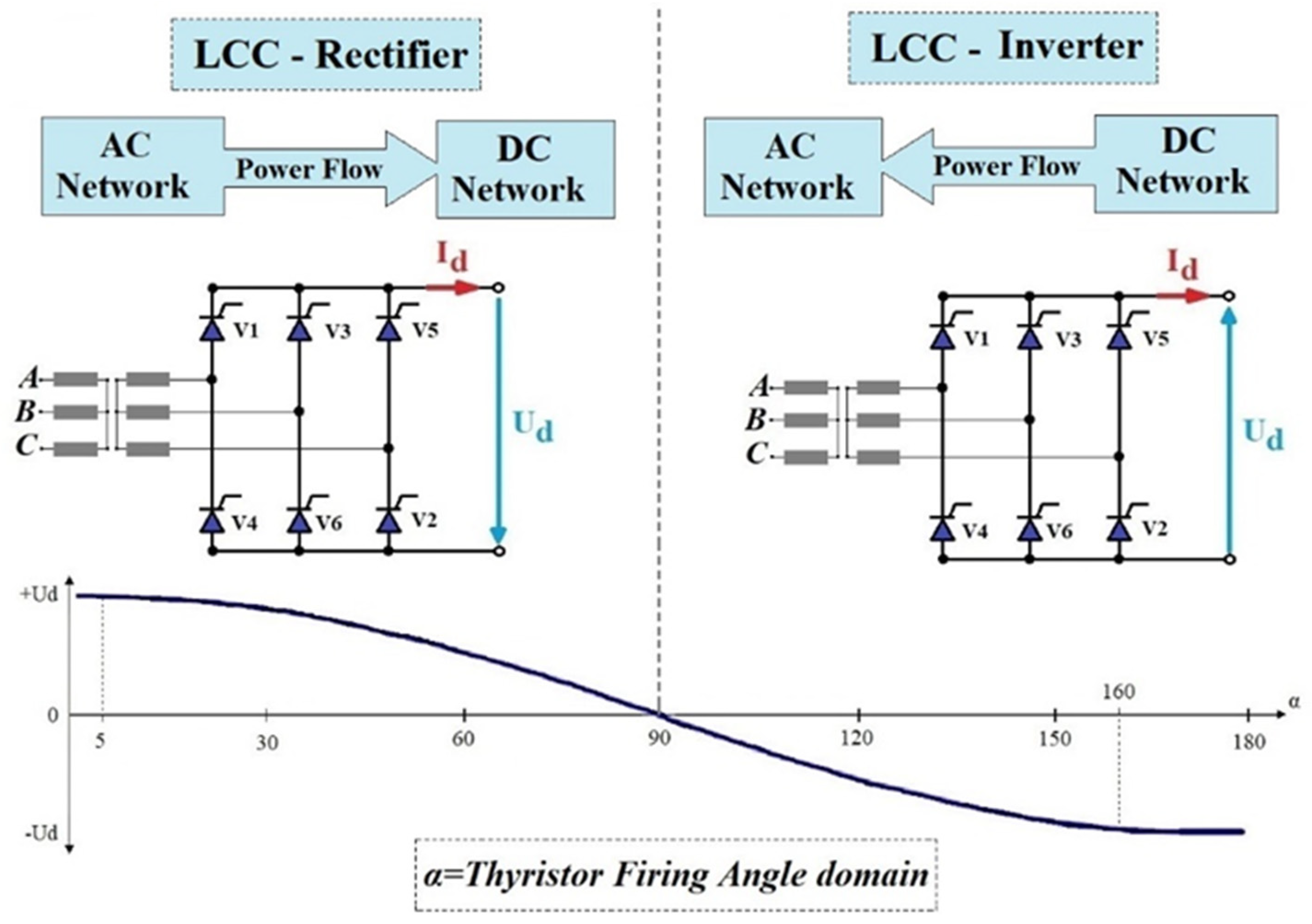 Figure 109. CSC-HVDC Converter operating modes.
4.3. VSC-HVDC Control Methods and Strategies
The main control methods used in VSC-HVDC systems are the “power angle” control strategy and “vector current” control strategy [41].
4.3.1 “Power Angle” Control Strategy
“Power angle” control, also called “voltage angle”, is probably the most direct method possible for controlling VSC-HVDC links.
The basic principle of the “power angle” control method is the following: the active power is controlled by changing the phase angle θ of the voltage associated with the VSC-HVDC connection, while the reactive power is controlled by changing the magnitude of the voltage of the VSC-HVDC connection [41,42,43].
A simplified control scheme usually used for this strategy is presented in FigureFigure 10 11 [41,42,43].
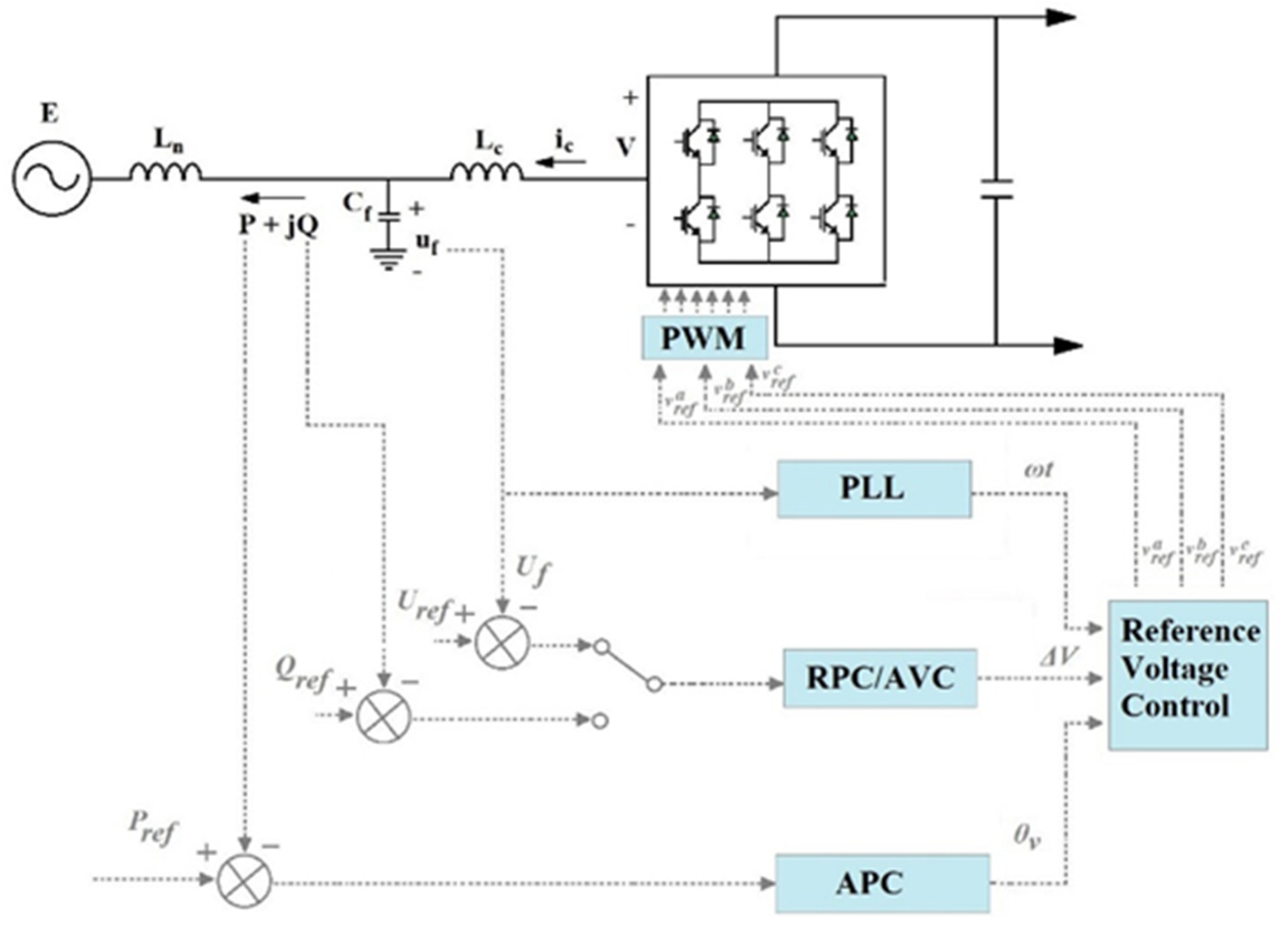 Figure 110. VSC-HVDC “power angle” control strategy.
In order to produce the tri-phase alternating voltage, the VSC-type device needs the following three control variables: magnitude, the phase angle, and the AC frequency. By using the “power angle” control method, the three variables are given by three different control loops, plus an additional synchronization loop, as follows [41,42,43].
- RPC (reactive power control)
- AVC (active voltage control)
- APC (active power control)
- PLL (phase-locked loop)
4.3.2 “Vector Current” Control Strategy
The “vector-current” control strategy consists of controlling the current associated with the VSC–HVDC converter station. It was first used in variable speed drives, where the VSC is connected to an AC motor [41,42,43].
In the case of VSC-HVDC-type connections, the “vector-current” control strategy consists of the independent control of the active and reactive power by means of the following cascaded loops: external control loops and the inner current control loop.
Compared to the “power angle”-type control method, which uses as input quantities ΔV, θv, and ωt, by means of which the three-phase reference voltages of the VSC-HVDC converter are generated, the “vector current” control method works in a similar fashion, using as inputs the reference voltages in axis d and q are as follows: vrefd, vrefq, and ωt [41,42,43] (Figure 11).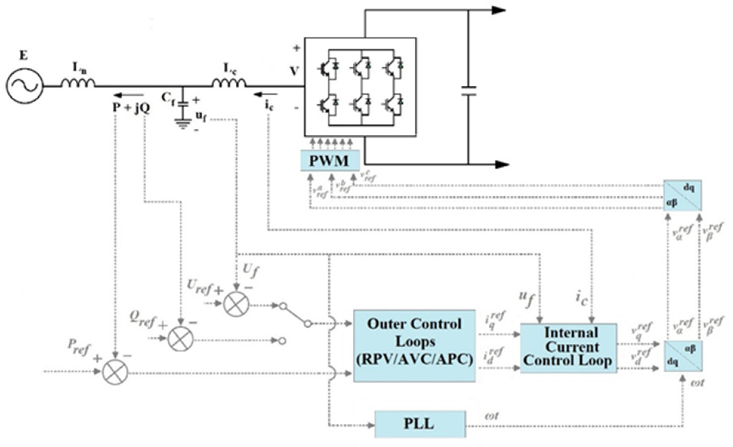
Figure 112. VSC-HVDC “vector current” control strategy.
5. Key Challenges Arising from the Use of HVDC Systems
The use of HVDC technology creates several issues, which need to be properly addressed:
- DC Circuit Breaker
- Reliability and Maintenance of HVDC Converter Substations
- Multi-Terminal HVDC System Operation
5.1. DC Circuit Breaker Solutions
The main issue regarding the implementation of circuit breakers (CB) in DC circuits is that there is no natural passage of fault current through zero, as in the case of classical AC systems. In DC circuits, the fault current can be brought to zero only by applying a higher counter voltage (Vb) than the operating voltage of the system [46].
A second problem is the need to dissipate a large amount of energy stored in the inductor of the DC line.
In order to solve those issues, a typical DC breaker arrangement is equipped with two additional circuits besides the main circuit breaker, an energy-absorbing circuit, and a commutating circuit [47,48].
The main types of DC circuit breakers are the following:
- Electromechanical Circuit Breaker;
- Solid-State Circuit Breakers (SSCB);
- Hybrid Circuit Breaker.
5.2. Reliability and Maintenance of HVDC Converter Substations
Given the rapid advancement of power electronics, a growing number of HVDC projects have been installed across the world. Their reliability and maintenance strategies have a direct influence on the system’s service security and, as a result, have a significant impact on network operation [55].
Recently, the emphasis has been on monitoring the operation of the converters in order to maintain proper operation. But due to the complexity of power converter structures and their degradation mechanisms, interpreting the information obtained by this technique (monitoring) is difficult, especially for non-experts [58,59].
6. Future Trends and Applications of HVDC Transmission Systems
The main future trends and applications of HVDC technology are the following:
- Modular Multilevel Converter (MMC) HVDC [62][63,64] [65];
- Cascaded Two-Level (CTL) HVDC [66,67,68,69];
- Classical Hybrid VSC-CSC HVDC Links [70,71,72,73];
- New VSC- HVDC Bipolar Topologies [74];
- Flexible LCC Converter [74];
- Use of VSC-HVDC for Voltage Stabilization and Transient Stabilization [75].
7. Conclusions
The most used applications of HVDC technologies are summarized as the following: long-distance bulk power transmission, submarine cable transmission, asynchronous ties, offshore wind power plant transmission, and multi-terminal HVDC systems;
At the moment, the main types of HVDC topologies used are the monopolar link, bipolar link (both with metallic return conductor or ground return path), back-to-back link, and homopolar link;
The primary components of the HVDC converter stations are presented for both VSC technology (particularly the use of phase reactor and DC capacitors) and CSC technology (particularly the use of DC and AC filters);
The main control strategies and U-I characteristics used for CSC-HVDC control are summarized (CCR, CCI, CIA, and CEA). Also, the main strategies for VSC-HVDC (power angle and vector control strategies) are presented with the associated active and reactive power control loops and the PLL loop (phase-locked loop) implementation;
Furthermore, the following series of key challenges arising from the use of HVDC technologies are discussed: DC circuit breaker solutions (the main types of existing circuit breakers are as follows: electromechanical, solid-state, and hybrid circuit breakers are presented), reliability and maintenance of HVDC converter substation, multi-terminal operation;
The study also takes a look at the future trends and applications of HVDC technologies such as MMC, CTL converters, hybrid implementation of HVDC links, new types of bipolar topologies, and network stability improvement applications of HVDC technology.