 +1 credit
| Version | Summary | Created by | Modification | Content Size | Created at | Operation |
|---|---|---|---|---|---|---|
| 1 | Sergey M Frolov | + 11164 word(s) | 11164 | 2021-12-14 03:08:54 |
Video Upload Options
The selective studies on environmentally friendly, combustion-free, allothermal, atmospheric-pressure, noncatalytic, direct H2O/CO2 gasification of organic feedstocks like biomass, sewage sludge wastes (SSW) and municipal solid wastes (MSW) are considered to demonstrate the pros and cons of the approaches and provide future perspectives. The environmental friendliness of H2O/CO2 gasification is well known as it is accompanied by considerably less harmful emissions into the environment as compared to O2/air gasification. Comparative analysis of the various gasification technologies includes low-temperature H2O/CO2 gasification at temperatures up to 1000 °C, high-temperature plasma- and solar-assisted H2O/CO2 gasification at temperatures above 1200 °C, and an innovative gasification technology applying ultra-superheated steam (USS) with temperatures above 2000 °C obtained by pulsed or continuous gaseous detonations. Analysis shows that in terms of such characteristics as the carbon conversion efficiency (CCE), tar and char content, and the content of harmful by-products the plasma and detonation USS gasification technologies are most promising. However, as compared with plasma gasification, detonation USS gasification does not need enormous electric power with unnecessary and energy-consuming gas–plasma transition.
1. Introduction
In the literature, there are several excellent books on biomass, SSW and MSW management and the fundamentals of incineration, pyrolysis, and gasification technologies, as well as multiple reviews on feedstock pretreatment/aftertreatment, advanced autothermal and allothermal, catalytic and noncatalytic gasifier designs and performances, and downstream technologies and syngas applications. We do not consider these issues herein. Thus, the objective of this review is to consider the selective studies on environmentally friendly, combustion-free, allothermal, atmospheric-pressure, noncatalytic, direct H2O/CO2 gasification of organic feedstocks like biomass, SSW, and MSW, and demonstrate the pros and cons of the approaches and provide future perspectives. The main issue addressed is the effect of gasification temperature and H2O/CO2-to-feedstock ratio on the gasification efficiency, syngas quality and yield, as well as the feasibility of in-situ control of syngas composition. These objectives and issues are the novel and distinctive features of the present review.
2. Definitions
2.1. Feedstocks
2.2. Processing Technologies
2.3. Gasifying Agents
2.4. Gasification Products
2.5. Gasification Reactions
2.6. Gasification Process Parameters
2.7. Gasification Technologies
3. Low-Temperature H2O/CO2-Assisted Allothermal Gasification
The thorough literature review [7] indicates that the main bottlenecks of existing allothermal, atmospheric pressure, noncatalytic, direct low-temperature H2O/CO2 gasification technologies of CCMs consist in
- low-quality syngas due to high content of tar (up to 27%wt. db) and CO2 (up to 30%vol. db),
- low gasification efficiencies due to high char residues (up to 40%wt. db),
- difficult in-situ gas quality control due to the need in long RTs of feedstock in the reaction zone (up to 100 min), and
- low yields of syngas due to low gas yields (below 90%wt. db), high tar and char contents and partial use of syngas (together with product char) for the production of heat required for gasification in the existing DFB gasifiers.
The current R&D efforts are mainly directed on feedstock preprocessing (e.g., biomass torrefaction) and postprocessing (reforming) of produced syngas, as well as improving feedstock reactivity by adding various catalysts. Despite some improvements in the CCE and other performance indices, all these activities lead obviously to the increase in the syngas production costs. As for the positive effect of catalysts on carbon conversion at 800–900 °C, it indicates that the feedstock conversion is kinetically controlled, i.e., heat and mass transfer is, in general, faster than chemical transformations. This kinetically controlled gasification is provided even by small fluidization velocities and low turbulence intensities in fluidized bed gasifiers on the level of 1 m/s. The increase in the gasification temperature other conditions being equal (e.g., at fixed flow rate of steam) results in the increase of both, the reaction rate and the intensity of heat and mass transfer, and by the decrease in the gas RT in a gasifier. The latter is due to the increase in the flow velocity of the gasifying agent caused by its density decrease with temperature. If the process is still kinetically controlled then all observed improvements in syngas quality detected in the experiments discussed above are mainly due to higher mixing intensity and trade-of between enhanced reactivity and reduced RT.
These considerations imply that for improving the process performance the kinetically controlled mode must be replaced by the diffusion-controlled mode when the chemistry is fast compared with heat and mass transfer processes. This can be attained only by increasing both the gasification temperature and velocity slip between phases (gasifying agent and feedstock particles). With increasing the gasification temperature and velocity slip between phases the rates of chemical reactions will increase drastically only if interphase and intraphase transport processes ensure the availability of hot reactants due to turbulent and molecular heat and mass transfer in both phases.
The optimal conditions for diffusion-controlled gasification could be obtained by applying the modern CFD approaches, which allow the optimization of gasifier design to ensure a required RT for gases and solids. Despite significant progress in understanding the various hydrodynamic and thermal processes in gasifiers and successfully simulating their overall performance, the existing approaches fail to adequately represent the gasification chemistry, one of the most important aspects of the process. Firstly, the chemistry used in the CFD studies is based on overall molecular reactions between valence-saturated molecules with high apparent activation energies. As a matter of fact, chemical reactions proceed through active intermediates like atoms and radicals via different reaction channels, and the corresponding reactions possess zero activation energies. Secondly, the reaction rates in the CFD studies are calculated based on the mean temperature and species concentrations. In reality, reaction rates are governed by local instantaneous temperatures and species concentrations, which could differ considerably from their mean values, in particular, at the presence of intense turbulent transport.
4. High-Temperature H2O/CO2-Assisted Allothermal Gasification
The thorough literature review [7] indicates that the main advantages of existing allothermal, atmospheric pressure, noncatalytic, direct plasma and solar high-temperature H2O/CO2 gasification technologies of CCMs consist in
- high-quality syngas due to negligible or low content of tar (less than 1 g/nm3) and CO2 (less than 6%vol. db),
- high gasification efficiencies with CCE attaining 100% due to negligible or small tar and char residues,
- easy in-situ gas quality control due to relatively short RTs of feedstock (less than 5–10 min) in the reaction zone, and
- high yields of syngas due to the use of electric or solar energy for the production of heat required for gasification.
The conventional heating systems with the operation temperatures up to 1400 °C could be considered as exception, because the lab-scale experiments with fixed bed and drop tube reactors show relatively low CCEs (77–84%) due to different reasons (residual char in locally cold zones, short RT, etc.).
The highest CCEs are attained in arc plasma systems evidently due to availability of high temperature and high velocity (up to ~1 km/s) gasifying agent. The presence of ions, electrons, excited molecules, and photons in the arc plasma jet enhances chemical transformations.
MW plasma is also efficient due to a specific heating mechanism of a feedstock. When a CCM is exposed to electromagnetic field, delocalized p-electrons start to move through broad regions of the material inducing its heating due to electrical resistance and formation of multiple localized hot spots (“microplasma”) with temperatures above 5000 °C. Chemical transformations in these hot spots are enhanced by the high-velocity microjets of plasma gases facilitating heat and mass transfer with the material. As for solar gasification of CCMs it can be considered as a means of storing solar energy in feedstock gasification products in a controlled form.
Despite many advantages, high-temperature plasma and solar gasification technologies have certain drawbacks which limit their widespread applications. Due to high operating temperatures water-cooling systems and or special construction materials and refractory liners are required for gasifier walls. Industrial scale arc and MW plasma technologies require enormous electric power. Moreover, the efficiency of plasma guns is at most 70–80%, and the lifetime of arc electrodes amounts hundreds of hours only. Despite very high plasma temperatures in the arc-jet (above 10,000 °С) and MW “microplasma,” the typical working temperatures in plasma gasifiers are only 1300–1700 °C to keep the reactor wall temperatures at an acceptable level dictated by refractory material of the wall. The question then arises what is the energy-consuming gas–plasma transition needed for if most of the feedstock is gasified at such a relatively low working temperature? As for the MW plasma, in addition to electric energy requirements its gasification efficiency highly depends on feedstock properties, which requires sorting operations. Also, there is often a need in mixing a feedstock with special materials possessing appropriate polarization properties in electromagnetic field, i.e., an additional operation which requires optimization is introduced. The main drawback of solar gasification is its intermittent character depending on time of day and weather conditions. Also, there is always a need in keeping a reactor window clean and providing uniform heating of feedstock.
In addition, plasma and solar gasification plant optimization requires highly sophisticated CFD software providing a solution of a coupled hydrodynamic (Navier–Stokes) and electrodynamic (Maxwell) equations complicated by chemical transformations and turbulent/molecular transport in a multicomponent environment. There are actually no publications on detailed numerical simulations of H2O/CO2 gasification of CCMs in plasma or solar gasifiers aimed at optimizing their operation conditions.
5. High-Temperature H2O/CO2-Assisted Allothermal Detonation-Based Gasification
5.1. Preliminary Remarks
In existing steam generators, superheated steam is usually obtained by heat transfer from the hot combustion products of some fuel: heat is first supplied for heating feed water to saturation temperature and its vaporization, and then to saturated water vapor. As a result, superheated steam of a given temperature is obtained at the outlet of steam generator, which cannot exceed the adiabatic combustion temperature of the fuel (for example, for a mixture of CH4 with air it is about 1950 °C) and is determined by the heat resistance of the material of heat exchanger walls. Even if the wall of heat exchanger is made of heat-resistant steel, its maximum temperature usually does not exceed ~1000 °C. Therefore, the production of USS, i.e., steam with a very high temperature (above 2000 °C) is a problem that has not yet been resolved. To solve this problem, a new method was proposed in [1] for generating USS using its shock or detonation compression and heating in a cyclic or continuous operation process based on pulse-detonation [4] or continuous-detonation [5] burning of fuel. First, in this method, instead of a relatively slow heat transfer through heat exchanger walls, a fast process of shock compression and heating of steam in a traveling shock wave (SW) or detonation wave (DW) is used, which increases the pressure and temperature by factors 25–30 and 8–10, respectively, within few microseconds. Secondly, in terms of energy efficiency detonation of fuel is more efficient than deflagration [4]. In [1] several options of producing USS are considered. The first option implies that USS is obtained by compression and heating of a detonable premixed fuel gas–oxidizer–steam mixture in propagating DWs. In the second option, USS is obtained through compression and heating of steam by propagating SWs generated by detonation of a fuel gas–oxidizer mixture. In both options, USS is additionally obtained as a product of detonation of fuel gas. The walls and internal elements of USS guns are heated to low temperature due to periodic filling of cool gas mixture, i.e., a USS gun can be made of conventional construction materials.
To get an insight on the parameters and composition of detonation products Figure 1 shows the results of thermodynamic calculations for H2O-diluted (40%vol.) stoichiometric oxygen mixtures of syngas with the H2/CO ratios of 1 (Figure 1a) and 2 (Figure 1b), as well as CH4 (Figure 1c), and C3H8 (Figure 1d). The curves show the equilibrium product gas composition at different temperatures and atmospheric pressure (P–T problem). Closed circles in the plots correspond to the temperature and composition of detonation products in the Chapman-Jouguet (CJ) point, while open circles correspond to the temperature and composition of detonation products after their isentropic expansion to 1 bar. As seen, the expanded detonation products of syngas have a temperature of 2300–2400 °C and contain 70–80% H2O, 15–20% CO2, up to 7% CO, 1–2% H2, and trace amounts of other species, including O2. The expanded detonation products of CH4 and C3H8 have a temperature of 2500–2600 °C and contain 60–70% H2O, 15–20% CO2, 4–7% CO, 2–3% H2, 2–3% O2 and trace amounts of other species.
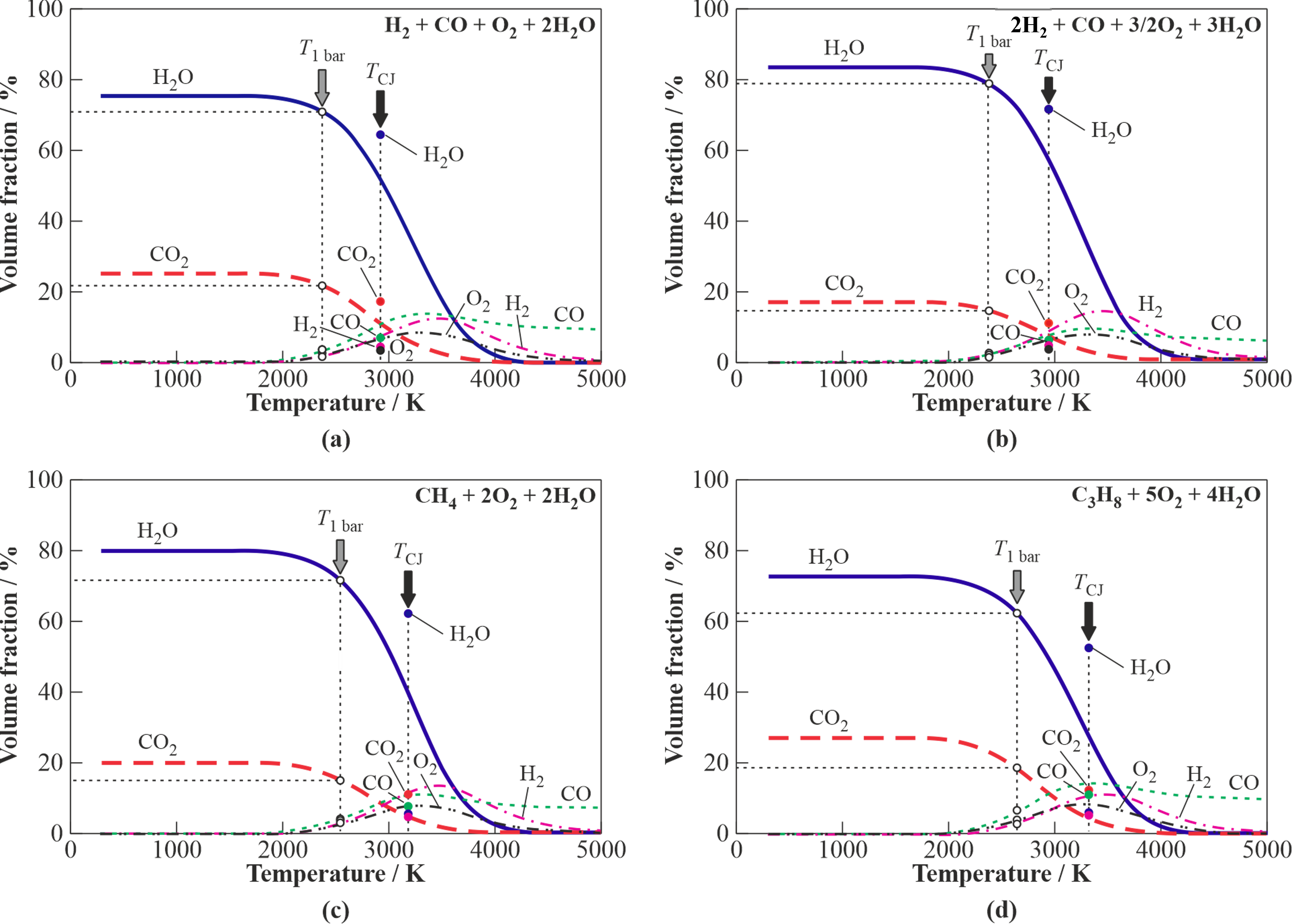
Figure 1. Equilibrium composition of detonation products for the steam-diluted (40%) stoichiometric fuel gas–O2–steam mixtures. Closed circles correspond to temperature and composition at the CJ point; open circles correspond to temperature and composition of detonation products isentropically expanded to 1 bar; (a) syngas (H2/CO = 1); (b) syngas (H2/CO = 2); (c) CH4; and (d) C3H8.
Thus, the syngas with the H2/CO ratios of 1 and 2 could be considered as fuel gas for obtaining a gasifying agent for organic feedstocks with the H2O/CO2 ratio of 4–5. As for CH4 and C3H8, these gases could be considered as good starting fuels for gasifiers operating on the USS obtained by gaseous detonations. The literature contains only few publications on the effect of H2O on the properties of gaseous detonations. The latter deal mainly with H2–O2 or H2–air mixtures as well as with CO–O2 or CO–air mixtures and H2/CO blends and are mostly related to the explosion safety of nuclear power plants rather than to the production of USS.
5.2. USS Detonation Guns
The invention [1] relates to methods and devices for producing USS for use in various technological installations including those for processing and disposal of biomass, SSW, MSW and other wastes using O2-free technologies. Figure 2 shows a schematic of the first version of the USS detonation gun. The main element of the device is a pulse-detonation tube (PDT) referred to as the pulsed USS gun. The inlet of the gun is connected with a steam manifold equipped with a valve. The gun and steam manifold are placed in the steam supply tank with a feed water level sensor and a temperature sensor. The device also includes a spark ignition, oxidizer and fuel supply, and control systems. The gun and the supply lines of the oxidizer and fuel are immersed in the feed water, and the steam manifold with a valve located in the upper part of the supply tank, which is filled with steam.
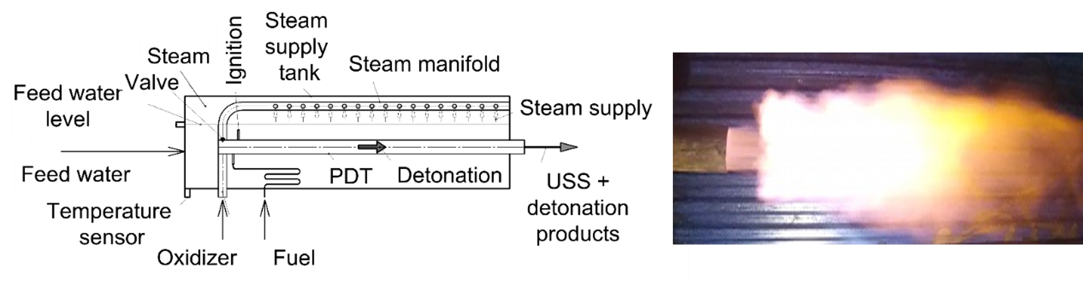
Figure 2. Pulsed detonation steam superheater (left) and its pulsed USS exhaust plume (right).
Figure 3 shows a schematic of the second version of the device. In contrast to the first version, the main element of the device is a continuous-detonation combustor referred to as the continuous USS gun equipped with a forced cooling system. All other systems are the same as in Figure 2. Note that the USS is issued from the gun at the velocity over 1 km/s and temperature above 2000 °C, as seen from the images of the exhaust plumes in Figures 2 and 3. Moreover, the issuing USS possesses the density, which is a factor of ~2 higher than the initial density of the low-temperature saturated steam. The ignition energy of pulsed and continuous detonations is negligible as compared to plasma torches.
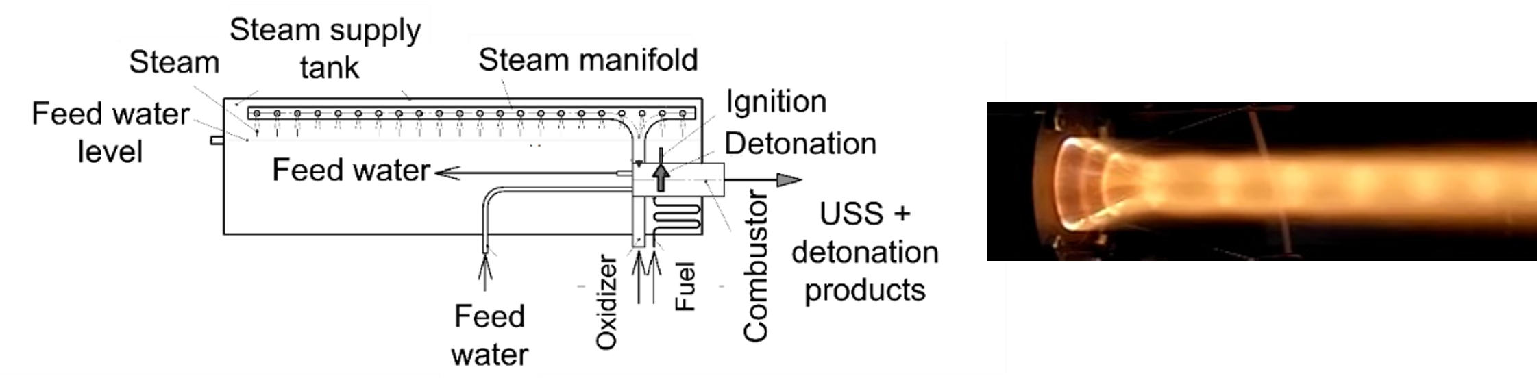
Figure 3. Continuous detonation steam superheater (left) and its continuous USS exhaust plume (right).
The proposed devices operate as follows. The device of Figure 2 operates cyclically at a frequency set by the control system. The operation cycle begins with filling the gun with a detonable mixture diluted by steam. The oxidant and fuel are fed into the gun through the corresponding supply lines. Steam is fed into the gun through a steam manifold with a valve from the upper part of the steam supply tank. The control system can provide several modes of device operation. In mode I, the oxidizer, fuel, and steam are fed into the gun simultaneously until it is completely or partly filled. In mode II, only steam is initially supplied to the gun, and then, in addition to steam, oxidizer and fuel are simultaneously supplied until the gun is filled with steam, and partly filled with the detonable mixture. In mode III, only steam is first supplied to the gun, and then the supply of steam is stopped and at the same time only the oxidizer and fuel begin to be supplied, and the filling of the gun continues until it is filled with such a stratified mixture in whole or in part. Upon reaching a given degree of gun fill, the supply of oxidizer and fuel stops. The filling of the gun with a combustible mixture ends when, at the command of the control system, the detonation process is initiated in the gun using the ignition system. The detonation process is carried out in accordance with the principle set forth in [4]. When the operation mode I is implemented, the USS is obtained because of its compression in a DW traveling through the fuel–oxidizer–steam mixture. When the operation modes II and III are realized, the USS is mainly obtained because of steam compression in a strong traveling SW. In all considered operation modes of the device, the resulting mixture of USS with an admixture of detonation products, e.g., CO2, is sent to a gasifier through the gun outlet section until the control system gives a signal to start the next operation cycle with filling the gun by a fresh portion of the WF.
In the device of Figure 3 the continuous-detonation operation process is supported in accordance with the principle set forth in [5]. Here, the USS is obtained because of its compression in a DW continuously rotating in the USS gun, filled with the fuel–oxidizer–steam mixture. Detonation of the fuel–oxidizer mixture produces an additional amount of USS, if fuel contains hydrogen. The resulting mixture of USS with an admixture of detonation products, e.g., CO2, is continuously injected in a gasifier through the gun outlet.
Figure 4 shows the 3D model and photographs of the pulsed USS detonation gun. For its operation, C3H8 and CH4 were used as starting fuels, and O2 as oxidizer.
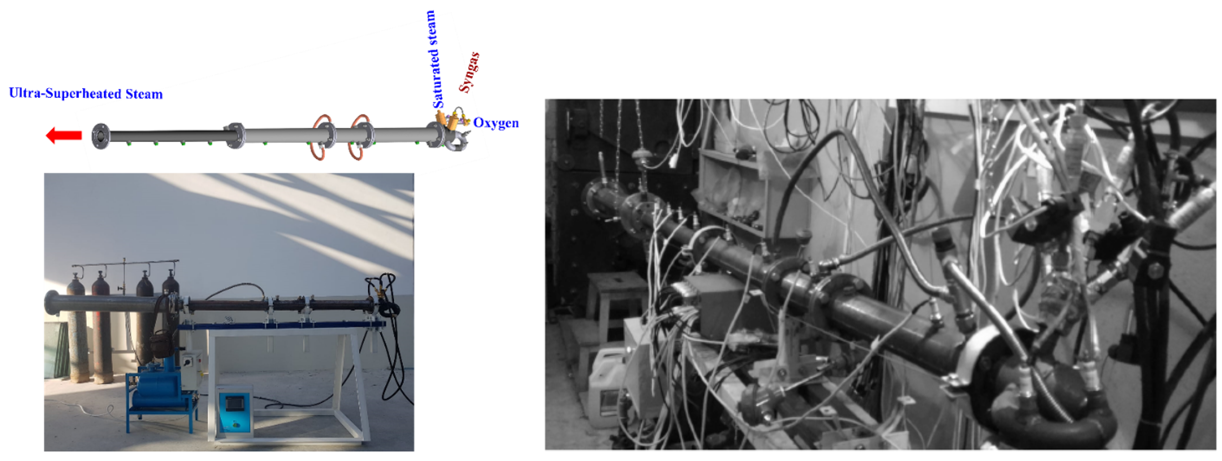
Figure 4. 3D model and photograph of the 50-mm i.d. USS gun (left) and USS gun at test firing (right).
The gun was a round tube 2.7 m long and 50 mm in diameter with one closed and one open end. The closed end was equipped with the ports for fuel gas and O2 supply. Downstream the ports, two standard spark plugs with the ignition energy of 100 mJ were mounted. A Shchelkin spiral made of steel wire with a diameter of 6 mm, pitch of 50 mm, and length of 1.5 m was inserted into the gun to ensure reliable detonation initiation. The gun was equipped with water cooling jacket. An electrically heated water boiler of adjustable capacity was a source of low-temperature steam for the USS gun. The boiler delivered steam with a temperature of 102 °C to the gun through a thermally insulated line under a small overpressure of ~8 kPa downstream the spark plugs. The gas feed system was set up to ensure complete fill of the gun with the mixture. In these conditions, DDT occurred at a short run-up distance from the ignition source in a wide range of compositions. The fuel-to-oxygen ER was varied from 0.14 to 1.77 in C3H8–O2–H2O mixtures and from 0.3 to 1.84 in CH4–O2–H2O mixtures. The volume fraction of H2O in the mixtures, X, was varied from 0 to 0.7. A set of eight ionization probes (IPs) was used to measure the velocities of reaction fronts including DWs. The velocity of reaction front was determined as the quotient of dividing the distance between the IPs by the time required for the reaction front to pass this distance.
Figure 5 shows the dependences of temperature and composition of isentropically expanded detonation products on steam volume fraction X in the stoichiometric C3H8–O2–H2O (Figure 5a) and CH4–O2–H2O (Figure 5b) mixtures. The shaded areas show the conditions in which DWs were registered experimentally. The temperature of expanded detonation products is seen to exceed 2000 and 2200 °C, respectively. The detonation products contain mainly USS (80 and 75%vol.) and CO2 (18 and 15%vol.), respectively. These findings correspond well with Figure 1c,d.
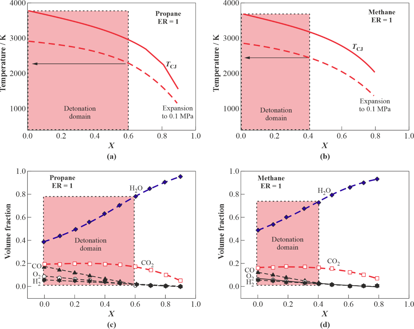
Figure 5. Parameters of detonation products of stoichiometric mixtures C3H8–O2–H2O and CH4–O2–H2O depending on H2O volume fraction (X) after isentropic expansion to atmosphere: (a,b) temperature, (c,d) composition. Conditions in which detonation is registered experimentally are indicated by shaded areas.
In general, results show that cyclic detonations of ternary C3H8–O2–H2O and CH4–O2–H2O mixtures allow producing USS with temperatures above 2000 °C at 1 bar. The maximum steam dilution in the mixtures can be as large as 60% for C3H8–O2–H2O and 40% for CH4–O2–H2O mixtures. The maximum content of USS in the expanded detonation products can attain 80%vol. for C3H8–O2–H2O and 75%vol. for CH4–O2–H2O mixtures with the rest represented mostly by CO2. It can be expected that a USS gun with a larger diameter of detonation tube will exhibit wider detonability limits in terms of the highest possible steam dilution of the initial mixture. This goes from the known dependence of detonability limits on tube diameter: the larger the diameter, the wider the concentration limits. Therefore, the amount of steam in USS guns with larger tubes can be larger. The measured temperature of gun walls in the tests with low operation frequency (below 1 Hz) was below 130 °C due to periodic filling of the USS gun with the cold gas mixture. The operation frequency was readily increased to 5–6 Hz by increasing the flow rates of mixture components.
Processing of organic wastes by such USS is accompanied by their pyrolysis, thermal destruction, and complete gasification. As a result, a high-quality syngas is generated, which can then be partly (estimated as 20% of total syngas yield) used as a fuel gas for the USS gun and for heat/electricity production and/or other downstream applications.
5.3. Gasification Plant 1
The objectives of invention [2] were to create a method and device for steam gasification of CCMs using high-speed USS jets obtained by shock or detonation compression of steam in a cyclic operation process with a pulsed USS detonation gun. Figure 6 shows a schematic of the USS gasifier. The main units of the device are a vortex reactor equipped with a pulsed USS gun and a CCM feeder. The USS gun is installed in the lower part of the vortex reactor and is oriented tangentially, as shown in the cross-section A–A. Inside the vortex reactor, lower and upper screens are provided for bordering the gasification region of CCM particles. The CCM feeder for supplying feedstock particles is made in the form of a metering device that provides the supply of feedstock particles to the USS gun upstream the inlet port of the vortex reactor. The proposed device operates as follows.
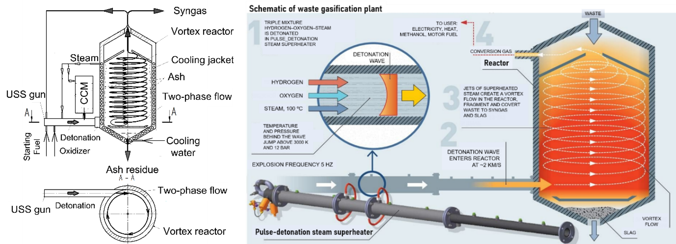
Figure 6. Waste gasification plant: (a) schematic, (b) operation principle.
The two-phase USS–CCM mixture is supplied to the vortex reactor cyclically with the frequency of USS gun operation, whereas production of syngas in the vortex reactor occurs in a continuous mode. The operation of the device includes three stages. Stage I is the start-up stage, at which the USS gun operates on the starting fuel. Stage II is the stage of reaching the operation mode, in which the USS gun gradually switches from the starting fuel to syngas produced in a vortex reactor. Finally, stage III is the working stage, in which the USS gun operates on a part of syngas produced in a vortex reactor, while the remaining part of syngas goes to the downstream equipment.
Feedstock particles are fed from the CCM feeder into a high-speed USS jet. In the USS jet, aerodynamic fragmentation of particle agglomerates and initial thermochemical transformation of a two-phase mixture occur. The two-phase mixture is directed tangentially into a vortex reactor, where, under conditions of a strongly swirling flow, feedstock particles are gasified to produce syngas. The resulting syngas is removed from the gasification zone to feed the USS gun and to go to downstream equipment. The bottom ash formed during feedstock gasification is fed to the bottom ash removal system. To ensure oxygen-free operation, the reactor operates at a slightly elevated pressure with the lowest overpressure on the level of 0.1–0.2 bar. Preliminary CFD calculations showed that the USS temperature in the central parts of the reactor exceeds 2000 °C, whereas the peripheral (near-wall) temperatures depend on the thermal boundary conditions and can attain the level of cooling water temperature. Nevertheless, due to the complex structure of the vortical high-speed flow in the reactor, resembling the flow structure in a reciprocating piston engine, the RT of feedstock particles in the high-temperature zone is sufficient for complete conversion.
Invention [2] is implemented in the lab-scale setup shown in Figure 7. It is based on the pulsed USS detonation gun of Figure 4 and uses natural gas (96% CH4) as a starting fuel and O2 as oxidizer. The vortex reactor is made of a standard 40-L gas cylinder. The feedstocks used are the coffee residue, WS, lignin, and water–coal emulsion (WCE). The WCE contained 60%wt. bituminous coal and 40%wt. water. The average size of coal particles in a WCE was 10–15 μm. The WCE was fed to the USS gun as a spray produced by a centrifugal injector with a mean droplet size of about 0.5 mm. The mass flow rate of feedstock in the setup attained 11 kg/h. The maximum wall temperature of the vortex reactor was 700 °C. The overpressure in the reactor was 0.2–0.5 bar. The S/F ratios were 0–3.
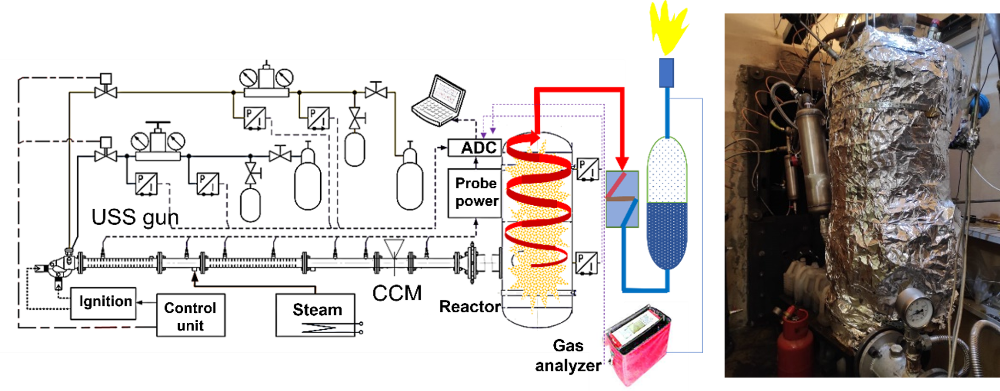
Figure 7. Laboratory scale gasification reactor: (a) schematic, (b) photograph.
The preliminary tests indicated that steam gasification of the feedstocks using the pulsed USS gun was comparable with plasma gasification in terms of syngas composition and conversion efficiency. Syngas composition depended on the feedstock. Thus, syngas produced by WS gasification tended to contain H2 and CO up to 40–45%vol. daf in proportion about 1:1 with small amounts of CO2 and CH4. The other important finding was that feedstock particles entering the USS gun were subject to extremely high dynamic and thermal stresses, which facilitated chemical transformations even before they entered the vortex reactor. Thus, upon feeding the WCE into the gun, coal particles radiated intensely at the gun exit despite the emulsion contained 40%wt. H2O. A preliminary gas analysis of the WCE gasification products showed that they mainly contained H2 and CO in a ratio close to 2:1. The degree of coal conversion depended on the USS gun operation frequency and reached 90% at a frequency of 5 Hz.
5.4. Gasification Plant 2
Invention [3] relates to method and device for neutralizing fly ash generated during incineration of MSW. Chemical compounds (dioxins, furans, etc.) as well as vapors of heavy metals (mainly Pb, Cd, Zn, Cu, Cr) formed during MSW incineration condense on fly ash particles in the economizer part of boilers with decreasing flue gas temperature. Fly ash particles concentrate up to 78% Cd, 43% Pb, and 38% Zn entering a furnace with MSW. The development of methods and devices reducing the toxicity of fly ash is an important task. One of the most effective ways to reduce the toxicity of fly ash in MSW incinerators is its neutralization by treatment with USS, which provides gasification and thermal destruction of toxic chemicals in the absence of O2, as well as the conversion of heavy metals into nonhazardous oxides and salts.
Figure 8 shows a schematic of the device [3]. The device includes a vortex reactor, a pulsed USS detonation gun split into two branch tubes, a feeder of toxic fly ash, an outlet for removing neutralized fly ash, and reactor cooling and control systems. The device operates as follows. Toxic fly ash in the form of small smoke particles is first separated from flue gases using cyclones and then supplied continuously or cyclically by the ash feeder to the branch tubes. The pulsed USS gun periodically generates supersonic jets of USS supplied through the branch tubes into the vortex reactor. The mass flow rate of toxic fly ash provided by the feeder and the frequency of issuing USS jets must be such as to ensure the injection of the supplied toxic fly ash into the reactor during the time between two successive detonation shots. Toxic fly ash under the action of USS jets enters the vortex reactor and is drawn into the vortex motion formed in the reactor due to the interaction of counter USS jets coming from two opposite branch tubes. The vortex motion in the reactor ensures the formation of stable high-temperature zones in the central region far from the reactor walls, while the wall temperature remains low, but above the steam condensation temperature, which is provided by the reactor cooling system. The stability of the high-temperature zones is maintained by the periodic injection of USS supersonic jets.
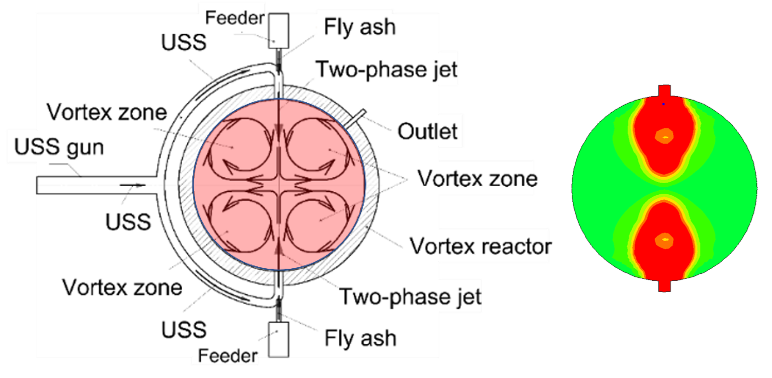
Figure 8. Schematic of fly ash detoxification reactor (left) and injection of USS supersonic jets (right).
Particles of toxic fly ash, involved in the vortex movement, circulate in the reactor, periodically entering the high-temperature zones, where they are rendered harmless under the action of USS in the absence of O2. Complex organic compounds adsorbed in fly ash, including dioxins, furans, etc. are thermally decomposed, gasified, and converted into the syngas containing simplest acids HCl, H2S, etc., while inorganic compounds are converted into the simplest oxides and salts. Periodic intense SWs accompanying the injection of USS supersonic jets prevent the agglomeration of fly ash particles. The cycle continues until a preset pressure rise in the reactor, e.g., by 30%. Thereafter a mixture of steam with the gasification products of the fly ash and detoxified fly ash itself are taken from the reactor for subsequent condensation of steam to obtain condensed products (acids, oxides and salts) and further disposal of neutralized fly ash.
3D CFD calculations demonstrating the method and device were performed in [3]. The calculation considered a spherical flow-type reactor with a volume of 110 L with two sections for supplying pulsed counter jets of USS (with a temperature above 2000 °C). Toxic fly ash was modeled by a set of spherical particles of constant diameter (0.1 or 1 mm), initially located in the region near the outlet of each of two branch tubes of the USS gun. The frequency of pulsed USS jets was set at 5 Hz. The following variables depending on time (t) were specified at the reactor inlets: the mass flow rate mg,in(t) and temperature Tg,in(t) of the detonation products of the stoichiometric ternary mixture 60% H2 + 30% O2 + 10% H2O, and also the mass flow rate mp,in(t) of particles. The dependences mg,in(t) and Tg,in(t) were obtained by a preliminary 3D calculation for a PDT of length L = 2 m attached to the reactor. The detonation velocity of such a mixture was D ≈ 2800 m/s. Calculations indicated that, once the DWs entered the reactor, most of the particles (97%) were surrounded by USS at 1700–2100 K. In 0.6 ms after the detonation shot, about 93% of particles were in contact with the USS flow at 1900–3500 K, and in ~100 ms after the shot, nearly all particles were in the USS flow with temperatures 1900–2300 K. Immediately before the next shot, only 3% of the particles were contacted by the USS at 1400–1500 K. The maximum calculated RT of particles in the reactor was 10–15 s, and their median mean RT was about 2 s. Estimates showed that more than 80% of the particles were contacted by USS with a temperature above 2000 K for at least 1 s. Under these conditions, the particles could be completely gasified. For example, the evaporation times of droplets of rapeseed and sunflower oil methyl ester (С18Н34О2) with diameters of dp = 0.1 and 1 mm even at 1000 K were less than 10 ms and 1 s, respectivel. It is easy to show, that at temperatures above 2000 K the rates of gas-phase oxidation of organic substances and soot by H2O and CO2 are extremely high; therefore, the rate of the overall gasification reaction is limited by the rate of particle thermal destruction or evaporation. Finally, Figure 9 shows the USS gasification plant designed based on the concept of [3]. The plant is designed for the mass flow rate of MSW/biomass up to 100 kg/h.
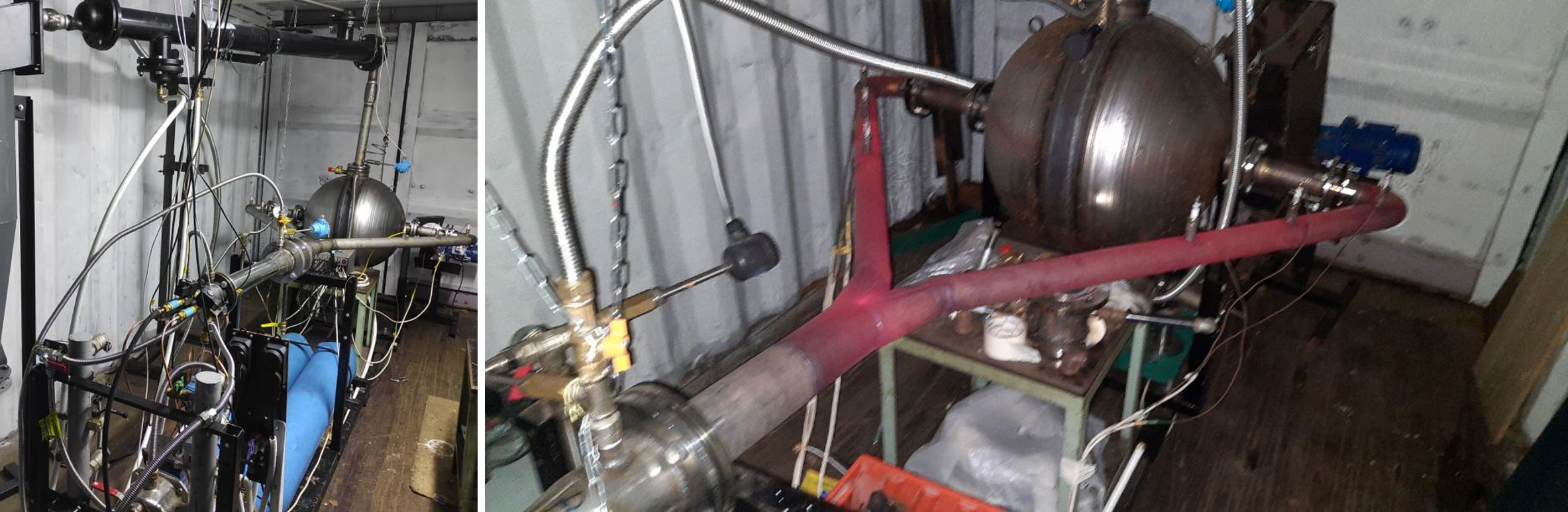
Figure 9. (a) Gasification plant based on pulsed USS gun and (b) thermal radiation of the uncooled USS gun during operation.
6. Conclusions
A selective literature review on atmospheric-pressure, combustion-free, allothermal, noncatalytic, direct H2O/CO2 gasification of organic feedstocks like biomass, SSW, MSW, etc. is presented, which demonstrates the pros and cons of the various approaches and provides future perspectives. In the review, three groups of gasification technologies are considered, namely low-temperature (500–1000 °C), high-temperature (above 1200 °C), and promising high-temperature detonation technology. The most important findings are given below:
- The existing low-temperature gasification technologies are mainly based on kinetically controlled feedstock conversion when gasification chemistry is slower than transport processes. Therefore, the low-temperature gasification technologies are characterized by relatively low-quality syngas, low gasification efficiencies, difficult in-situ gas quality control, and low yields of syngas.
- The existing high-temperature plasma and solar gasification technologies provide high-quality syngas, gasification efficiencies up to 100%, easy in-situ gas quality control, and high yields of syngas. However, despite these advantages, they have certain drawbacks which limit their widespread applications. Firstly, industrial scale arc and MW plasma technologies require enormous electric power, and the efficiency of plasma guns is at most 70–80%, whereas solar gasification depends on time of day and weather conditions. Secondly, in view that most of feedstock in plasma guns is gasified at relatively low temperatures (1300–2000 °C), the gas–plasma transition appears an unnecessary energy-consuming stage. Thirdly, in addition to water-cooling systems they require special construction materials and refractory liners for gasifier walls.
- As a more efficient alternative to high-temperature plasma guns, a novel environmentally friendly USS detonation gun technology for gasification of organic wastes is proposed and demonstrated. Such a technology has several attractive features. Firstly, in a USS gun, high gasification temperatures (above 2000 °C) are attained by detonating a part of produced syngas (about 20%), while the energy consumption for detonation ignition is negligible. Secondly, the corresponding gasification plant can be made from conventional structural materials. Thirdly, such a plant can be readily scaled-up from small to large scale by applying multiple USS guns of the same power or guns of high power, keeping in mind that detonation phenomenon can be readily scaled up. Moreover, such a plant can be implemented as a mobile version, e.g., in the form of a trailer to a car or onboard ship. Nevertheless, for further progress in this direction there is a need in a thorough economic analysis of organic waste H2O/CO2 gasification using the USS detonation gun technology.
References
- Frolov, S.M.; Smetanyuk, V.A.; Avdeev, K.A.; Nabatnikov, S.A. Method for Obtaining Highly Overheated Steam and Deto-nation Steam Generator Device (Options). Patent of Russian Federation No. 2686138, 24 April 2019. Priority dated 26 February 2018.
- Frolov, S.M.; Smetanyuk, V.A.; Nabatnikov, S.A. Method of Gasification of Coal in a Highly Overheated Water Vapor and Device for Its Implementation. Patent of Russian Federation No. 2683751, 1 April 2019. Priority dated 24 May 2018 (WO2019/226074 A1 dated 28 November 2019).
- Frolov, S.M.; Nabatnikov, S.A.; Diesperov, K.V.; Achildiev, E.R. Method for Decontamination of a Fly Ash Formed during Burning of Wastes and a Device for Its Implementation. Patent of Russian Federation No. 2739241, 22 December 2020, priority dated 11 June 2020.
- Roy, G.D.; Frolov, S.M.; Borisov, A.A.; Netzer, D.W. Pulse detonation propulsion: Challenges, current status, and future perspective. Prog. Energ. Combust. Sci. 2004, 30, 545–672.
- Bykovskii, F.A.; Zhdan, S.A. Continuous Spinning Detonation; Lavrentiev Institute of Hydrodynamics Publ.: Novosibirsk, Russia, 2013.
- Lewis, F.M. Generation of an Ultra-Superheated Steam Composition and Gasification Therewith. U.S. Patent US20030233788A1, 2007.
- Frolov, S.M. Organic Waste Gasification: A Selective Review. Fuels 2021, 2, 556-650. https://doi.org/10.3390/fuels2040033

