 +1 credit
| Version | Summary | Created by | Modification | Content Size | Created at | Operation |
|---|---|---|---|---|---|---|
| 1 | Hongye Zhang | + 2104 word(s) | 2104 | 2021-04-21 05:16:27 | | | |
| 2 | Rita Xu | Meta information modification | 2104 | 2021-05-07 09:58:55 | | | | |
| 3 | Rita Xu | + 813 word(s) | 2917 | 2021-05-13 11:05:45 | | | | |
| 4 | Hongye Zhang | -3 word(s) | 2914 | 2021-05-13 12:40:28 | | | | |
| 5 | Peter Tang | Meta information modification | 2914 | 2021-09-14 10:51:14 | | |
Video Upload Options
Alternating current (AC) loss is generated due to the movement of magnetic vortices within the superconductor when experiencing time-varying currents or magnetic fields (or both). AC loss can be categorized into transport current loss and magnetization loss based on the AC source. Particularly, when a superconductor carries a direct current (DC) and is simultaneously exposed to an AC field, dynamic resistance occurs and leads to dynamic loss. Quantification and minimization of AC loss are crucial because the produced heat can not only present severe challenges to the cryogenic systems but also impair the reliability of superconducting devices, leaving a safety hazard. To quantify the AC loss of superconductors, analytical formulae, numerical models, and experimental measurements have been widely adopted. Concerning AC loss minimization techniques, the modification of superconductor structures (filamentation and twisting), flux diverters, as well as winding techniques have been widely exploited. This entry serves to clarify the characteristics and quantification methods of AC loss as well as its minimization techniques in superconductors. It is believed to help deepen the understanding of AC loss and deliver a helpful guideline for future research efforts.
1. Introduction
Superconductors are characterized by zero electrical direct current (DC) resistance, i.e., they exhibit no power dissipation when carrying a DC. However, the adopted superconductors have to experience time-varying currents or magnetic fields in many applications, e.g., superconducting electrical machines, superconducting flux pumps, etc. In this case, power dissipation is generated, which is defined by the term Alternating Current (AC) loss. In fact, the external field penetrates Type-II superconductors in the form of magnetic vortices pinned to the superconductor material. Variation of the transport current or external magnetic field (as in an AC cycle) can lead to the movement of vortices inside the superconductor, which induces currents in the normal conducting regions associated with the core of each vortex where AC power dissipation is thus produced [1].
It is a common practice (related to experiments) to categorize AC loss based on the AC source. Therefore, AC loss can be classified into transport current loss and magnetization loss. Magnetization loss describes the dissipation due to purely external magnetic fields without transport current, and transport current loss is caused by the carried current inside the superconductor in the absence of external magnetic fields [2]. Magnetization loss consists of eddy current loss, hysteresis loss, and coupling loss. Hysteresis loss is generated by flux pinning and the loss per cycle is proportional to the area of the hysteresis loop. Coupling loss occurs due to the flowing of eddy current induced by external magnetic fields between filaments in multifilamentary conductors. Therefore, coupling loss can also be a problem for striated superconducting tapes. Eddy current loss is the ohmic power dissipation generated by the eddy current in the metal matrix. Transport current loss includes hysteresis loss and flux flow loss. Hysteresis loss occurs because the carried time-varying current provides the self-field. Flux flow loss happens due to more and more vortices moving in the superconductor with the increase of the transport current (or the load proportion between the transport current and the self-field critical current). Particularly, when a superconductor carries a DC and experiences simultaneously a time-varying magnetic field, the interaction between the DC transport current and the moving vortices leads to a time-averaged potential drop along the superconductor [3]. Dynamic resistance and dynamic loss are thus proposed to characterize the resistance and power dissipation generated in this specific case.
2. Fundamental characteristics of AC loss
Let us consider a thin high temperature superconducting (HTS) film of a coated conductor (CC) with the width of 2w and the thickness of h, having Ic0 as the self-field critical current. When the HTS film is exposed to an AC magnetic field perpendicular to its wide surface, with the amplitude of Bext, the Brandt equation can be utilized to quantify the average magnetization power loss per unit length (W/m), Pmag, as [4][5]
 (1)
(1)
where H0 = Bext /µ0, Hc denotes the characteristic field given by Ic0/(2wπ), µ0 is the free space permeability, and f refers to the frequency of the AC field. Equation (1) shows that the magnetization power loss is in a positive correlation with the amplitude of the external field and the square of the film width.
When the HTS thin film carries an AC current with the amplitude of It, according to the Norris equation, the average transport power loss per unit length (W/m), Ptrans, can be written as [6]
 (2)
(2)
where i represents the load ratio, determined by i = It / Ic0, and f is the frequency of the AC current. It can be found that the transport power loss increases positively with the load ratio. Actually, it can increase even more rapidly due to flux-flow dissipation. At sufficiently high load ratios, some of the current will flow in the normal conducting parts of the HTS CC leading to a resistive contribution [1].
When the HTS film carrying a DC, It, is exposed to an AC field with the amplitude of Bext, the full-range dynamic power loss (W/m) can be calculated by [7]
 (3)
(3)
where n refers to the power exponent in the E-J power law [8], E0 represents the characteristic electric field with E0 = 10-4 V/m, B0 denotes the characteristic field in the Jc(B) dependence [9][10], and Bth is the threshold field defined by [11]
 (4)
(4)
It should be noted that in Equation (3) n is even. When n is odd, the upper bound of summation has to be changed correspondingly [7]. According to Equation (3), it can be seen that the dynamic power loss is in positive correlation with the width of the film, the load ratio, as well as the external field. When the HTS film with a low load ratio experiences a low external field, its dynamic loss is mainly determined by the first term in (3) and varies almost linearly with the external field. However, at both high load ratios and high external fields, the dynamic loss is dominated by the second term in (3) and varies rapidly in a non-linear way with the external field, putting the CC in danger of a quench. More analytical formulae for calculating the AC loss of distinct HTS geometries can be found in the review article [12].
3. Numerical modelling and measurement of AC loss
According to Equations (1)-(3), it is intuitively understood that the magnetization power loss, transport power loss, and dynamic power loss all increase linearly with frequency. However, at sufficiently high frequencies, the transport current and magnetic flux will be driven towards the normal conducting regions of the CC under the skin effect [13][14]. In this case, (1)-(3) become inapplicable to accurately predict the AC loss in HTS CCs. Besides, analytical loss calculations are imperfect in that the formulae have been derived based on some fundamental assumptions, e.g., constant critical current, homogenous external field, thin film approximation for HTS CCs, etc. Additionally, the analytical equations are normally limited to simple structures, e.g., single tapes or wires. Therefore, numerical models and experimental measurements appear to be indispensable tools to quantify the AC loss of complex geometries in a complicated electromagnetic environment.
3.1. Numerical modelling methods
The first step for numerically calculating AC loss is to build a geometric model (1D, 2D, or 3D) for the studied object based on its physical properties, e.g., symmetry, and then it should be discretized in a mesh of elements. Afterwards, one has to choose a numerical method and a formulation. The primary modelling of HTS CCs is based on Maxwell’s equations and finite element methods (FEM), which is typically achieved by the T-ϕ formulation, A-V formulation, E-formulation, H-formulation, and the variants or combinations of these formulations, as reviewed in [12]. The FEM-based numerical models can be incorporated into commercial software, e.g., COMSOL Multiphysics, and ANSYS. Once the electromagnetic state variables in the chosen formulation are obtained, the AC loss can be calculated according to the methods presented in Section II-C in [15].
Figure 1 shows the variation of the transport power loss of a 10-mm wide HTS CC with a 75-μm thick Ni–W substrate carrying sinusoidal currents. It can be seen that the modelled total AC loss of the whole CC based on the H-formulation is in good agreement with the measured data. Through numerical modelling, we can access quantities not available from measurements, e.g., the loss generated in various layers of the CC, and the saturation of magnetic loss, etc. It should be noted that the AC loss in the HTS layer of a CC with a magnetic substrate is different from that of a CC with a non-magnetic substrate. In this case, the analytical formulae, e.g., the Norris equation, are not accurate to calculate the AC loss and thus numerical modelling is the best and only way to quantify the AC loss in the HTS layer.
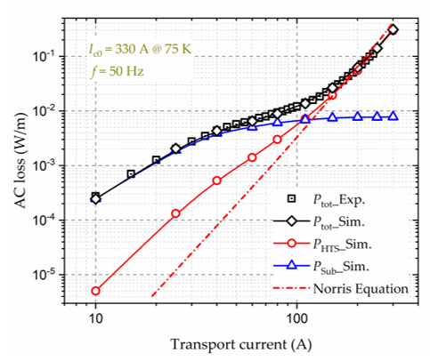
Figure 1. Variation of the AC loss of a 10 mm wide HTS CC with a magnetic substrate with sinusoidal transport currents. The self-field critical current, Ic0, of the HTS CC is 330 A at 75 K, and the frequency, f, of the AC magnetic field is 50 Hz. Experimental data are taken from [16]. Exp.-Experiment, Sim.-Simulation.
To overcome the limitations of the full models and decrease the modelling complexity, e.g., in the case of simulation of numerous HTS stacks or turns, some simplification approaches have been put forward, e.g., the homogenization method [17], the multi-scaling approach [18], and the densification method [19]. There exist other modelling methods for the calculation of AC loss, such as the integral equation method [20], and the Minimum Magnetic Energy Variation (MMEV) method [21] as well as Minimum Electro-Magnetic Entropy Production (MEMEP) method [22]. The integral equation method is based on the use of Green’s function to transform the partial differential equations into integral equations, which can avoid the meshing of non-conducting regions. As for the MMEV and MEMEP methods, they are computationally time-efficient and potentially promising for demanding 3D problems.
3.2. AC loss measurement approaches
There exist three main approaches for measuring AC loss of superconductors, namely electric, magnetic, and calorimetric methods.
The electric method is extensively used on account of its fast measurement speed and high sensitivity. It can be exploited to measure both AC transport current loss and magnetization loss, which consists of three types of techniques: the pick-up coil method, lock-in amplifier method, and the combination of the two techniques. Two typical electrical circuits of the pick-up coil method and the lock-in amplifier technique are presented in Figure 2.
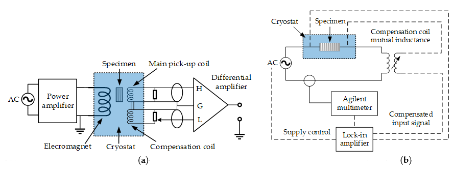
Figure 2. Typical electric circuits for the AC loss measurement. (a) Pick-up coil method, adapted from [23]. (b) Lock-in amplifier technique, adapted from [2].
The magnetic method is regularly used to measure the hysteresis loss of superconductors. By measuring the voltages over pick-up coils around the superconducting specimen, which are then multiplied by the field strength and integrated over one cycle, the variation in the magnetic moment of the specimen can be identified [24]. The magnetic moment of the superconductor can be obtained with different methods, such as pick-up coils, Hall probes, superconducting quantum interference devices (SQUID), and vibrating-sample magnetometers (VSM). The measurement system is usually composed of the AC magnet, cryostat, pick-up coil, high-current amplifier, compensation coil, as well as data acquisition system. Hysteresis loss can also be acquired through the measurement of the imaginary part of complex AC susceptibility. The equivalent circuit for a typical AC susceptibility measurement system is shown in Figure 3.
The disturbance of AC fields or currents is intrinsic in the electric and magnetic measurement approaches, which is not a concern for the calorimetric method. Besides, the reliability of the calorimetric method is not affected by the phase shift between the external field and the transport current. Therefore, the calorimetric method can be applied to a complicated electromagnetic environment. With the calorimetric method, the total AC loss can be obtained by the measurement of either the temperature rises of superconductors or the evaporated cryogen.
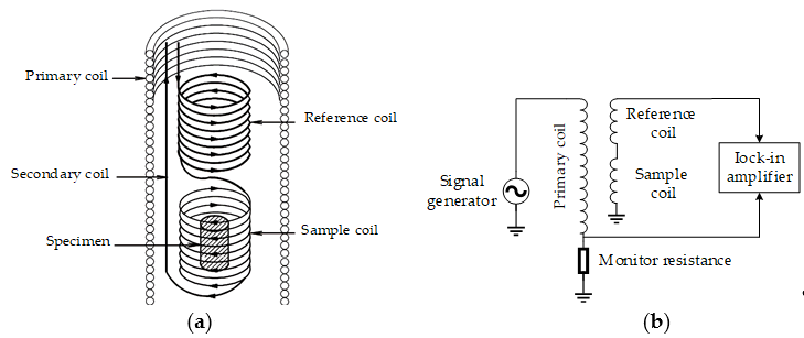
Figure 3. Diagrams of the measurement systems for AC susceptibility of superconductors, adapted from [25]: (a) Geometrical arrangement of different coils; (b) Equivalent circuit for the measurement system using the magnetic method.
To measure the temperature variation, cryogenic thermometers, cryostat, thermal isolation material, and voltage taps are usually needed. The calibration of the thermometers is the first step. Then, the variation of the thermal conductivity of the superconducting sample with temperature needs to be measured. Another temperature variation detection method is optical fiber Bragg grating (FBG) [26], which takes advantage of the wavelength variance dependence of temperature.
The minimum measurable loss by the temperature rise measurement method is approximately 10-4 W/m. The measurement system using FBG is presented in Figure 4.
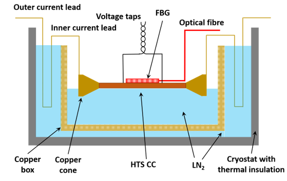
Figure 4. Diagram of the calorimetric measurement system based on the optical fiber Bragg grating for AC loss of HTS tapes, adapted from [26].
The temperature rise due to dissipated energy will lead to the evaporation of the cryogen; thus, the measurement of AC loss can be achieved by measuring the gas flow volume of the evaporating cryogen, namely the boil-off method [27]. The corresponding measurement system is mainly composed of the AC power supply, non-metal cryostat, cryogen, heat exchanger, thermostat, and gas flow meter. It should be noted that the measurement of cryogen evaporation is time-consuming and does not possess a high accuracy, with the minimum measurable loss of 10-4~10-2 W/m.
4. AC loss reduction techniques
The large cross-sectional aspect ratio of HTS CCs leads to a high magnetization loss; thus the striation of the HTS layer to a filamentary structure has been proposed to minimize the AC loss [28][29]. Figure 5 demonstrates the measured magnetization loss of a 12-mm-wide YBCO CC with different filaments, in which the Brandt equation agrees well with the experimental data for the original HTS CC. It can be seen that the filamentation of HTS CCs can effectively decrease the AC loss, and the loss reduction effect gets enhanced with the increasing number of filaments. According to Equation (1), the magnetization loss is proportional to the square of the width of the HTS CC, thus a reduction by a factor N is expected if the HTS layer is striated to N filaments. However, this is true only at sufficiently high fields because at lower fields the superconductor volume penetrated by the field is larger in uncoupled filaments than in a nonstriated CC [30] and hence the loss of a filamentized CC can be greater than that of the original one, as shown in Figure 5. Different from conventional filamentary HTS CCs, a soldered-stacked-square wire has been proposed in [31], which can help to decrease AC loss by 80% compared with originally uncut tapes.
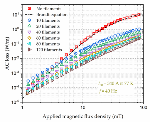
Figure 5. Variation of the AC loss of a 12-mm-wide YBCO coated conductor (CC) and its filamentized tapes with externally applied AC magnetic fields. The self-field critical current, Ic0, of the YBCO CC is 340 A at 77 K, and the frequency, f, of the AC magnetic field is 40 Hz. Experimental data are from [30].
Another method to reduce the AC loss of HTS CCs is to change their physical arrangements, e.g., the Roebel concept, Rutherford cable, and Conductor on Round Core (CORC®) wire. Because of their periodically repeating and transposed physical properties, the twist structure can effectively reduce the transport current loss and magnetization loss compared with conventional HTS stacks, especially at medium-high currents and low magnetic fields [31]. The AC loss and inter-tape contact resistance of multiple cabling methods, including REBCO CORC®, Roebel, and stacked tape cables have been compared in [32]. It is found that the CORC® cable has lower hysteresis loss in an alternating magnetic field perpendicular to the wide side of the REBCO layer, compared with Roebel cables and non-twisted conductors.
In addition to the modifications to the physical structure of HTS CCs, the application of magnetic materials as flux diverters in electrical machines can also serve to decrease the AC loss of superconductors. According to the Jc(B) dependence, the field component perpendicular to the wide surface of an HTS CC has a greater impact on the critical current compared to the parallel component, and thus causes higher AC loss in the CC. An ideal flux diverter material exhibits high permeability; thus it can be applied to divert magnetic flux orientation to reduce the perpendicular field component and achieve the reduction of AC loss [34][35].
Apart from the structure modification of superconductors and the application of ferromagnetic flux diverters, winding techniques are another effective way to decrease the AC losses of coils. A winding method for multilayer-type conductors composed of stacked Rutherford-type cables by controlling the twist angle around the conductor axis has been proposed in [36], which can help decrease the total AC loss by 74% compared to the conventional winding method. Two auxiliary windings have been exploited in [37] to reduce the leakage flux in HTS transformers so that the AC loss of HTS coils can be decreased by about 13.6%. The optimization of the turn-to-turn resistivity can contribute to the reduction of AC loss, as reported in [38][39]. A shaped profile winding for minimal AC loss in conventional electrical machines has been reported in [40], which maximizes slot area utilization to realize an improved low-speed and DC performance while achieving low AC loss. The proposed shaped profile winding technique possesses the potential to be adapted to superconducting windings. By orienting the CC or coil appropriately with respect to the external field, a substantial AC loss reduction can also be achieved [41].
5. Conclusions
This entry has presented multiple AC loss-related topics: AC loss mechanism and analytical formulae, modelling methods, measurement approaches, as well as loss minimization techniques. It has provided a useful reference for loss quantification and loss controlling in Type-II superconductors and delivered a helpful guideline for future research efforts.
References
- F. Grilli and F. Sirois (2016). AC Losses and Numerical Modeling of Superconductors. In digital Encyclopedia of Applied Physics, Wiley‐VCH Verlag GmbH & Co. KGaA (Ed.). https://doi.org/10.1002/3527600434.eap770.
- M. D. Ainslie (2012). Transport AC loss in high temperature superconducting coils (Doctoral thesis). https://doi.org/10.17863/CAM.14029.
- Z. Jiang et al, "Dynamic resistance of a high-Tc coated conductor wire in a perpendicular magnetic field at 77 K", Supercond. Sci. Technol., vol. 30, no. 3, 03LT01, 2017.
- M. R. Halse, "AC face field losses in a type II superconductor", J. Phys. D Appl. Phys., vol. 3, no. 5, pp. 717-720, 1970.
- E. H. Brandt and M. Indenbom, "Type-II superconductor strip with current in a perpendicular magnetic field," Phys. Rev. B, vol. 48, no. 17, pp. 12893–12906, 1993.
- W. T. Norris, "Calculation of hysteresis loss in hard superconductors carrying ac: isolated conductors and edges of thin sheets, " J. Phys. D: Appl. Phys., vol. 3, pp. 489–507, 1969.
- H. Zhang, et al., "A full-range formulation for dynamic loss of HTS coated conductors," Supercond. Sci. Technol., vol. 33, no. 5, 05LT01, 2020.
- J. Rhyner, "Magnetic properties and AC-losses of superconductors with power law current-voltage characteristics," Physica C, vol. 212, pp. 292–300, 1993.
- Y. B. Kim, C. F. Hempstead, and A. R. Strnad, "Critical persistent currentsin hard superconductors," Phys. Rev. Lett., vol. 9, no. 7, pp. 306–309, 1963.
- P. W. Anderson, "Theory of flux creep in hard superconductors," Phys. Rev. Lett., vol. 9, no. 7, pp. 309–311, 1963.
- G. P. Mikitik and E. H. Brandt, "Generation of a dc voltage by an ac magnetic field in type-II superconductors," Phys. Rev. B, vol. 64, 092502, 2001.
- H. Zhang, et al., "Alternating current loss of superconductors applied to superconducting electrical machines," Energies, vol. 14, no. 8, pp. 2234. 2021.
- H. Zhang et al., "Modelling of electromagnetic loss in HTS coated conductors over a wide frequency band", Supercond. Sci. Technol., vol. 33, no. 2, 025004, 2020.
- H. Zhang, et al., "Dynamic loss and magnetization loss of HTS coated conductors, stacks, and coils for high-speed synchronous machines," Supercond. Sci. Technol., vol. 33, no. 8, 084008, 2020.
- F. Grilli et al, "Computation of Losses in HTS Under the Action of Varying Magnetic Fields and Currents," IEEE Trans. Appl. Supercond., vol. 24, no. 1, pp. 78-110, 2014.
- D. N. Nguyen et al., "A new finite-element method simulation model for computing AC loss in roll assisted biaxially textured substrate YBCO tapes”, Supercond. Sci. Technol., vol. 23, 025001, 2009.
- V. M. R. Zermeno, A. B. Abrahamsen, N. Mijatovic, B. B. Jensen and M. P. Soerensen, "Calculation of AC losses in stacks and coils made of second generation high temperature superconducting tapes for large scale applications", J. Appl. Phys., vol. 114, no. 17, pp. 173901-1-173901-9, 2013.
- V. M. R. Zermeno et al., "Towards Faster FEM Simulation of Thin Film Superconductors: A Multiscale Approach," IEEE Trans. Appl. Supercond., vol. 21, no. 3, pp. 3273-3276, 2011.
- E. Berrospe-Juarez, F. Trillaud, V. Zermeno, and F. Grilli, "Advanced electromagnetic modeling of large-scale high temperature superconductor systems based on H and T-A formulations", Supercond. Sci. Technol., vol. 34, no. 4, 044002, 2021.
- R. Brambilla, F. Grilli, L. Martini, and F. Sirois, "Integral equations for the current density in thin conductors and their solution by finite element method," Supercond. Sci. Technol., vol. 21, no. 10, 105008, 2008.
- E. Pardo et al, "Current distribution and ac loss for a superconducting rectangular strip with in-phase alternating current and applied field," Supercond. Sci. Technol., vol. 20, no. 4, pp. 351–364, 2007.
- E. Pardo, J. Souc, and L. Frolek, "Electromagnetic modelling of superconductors with a smooth current-voltage relation: Variational principle and coils from a few turns to large magnets," Supercond. Sci. Technol., vol. 28, no. 4, 044003, 2015.
- S. Kawabata et al, "Standardization of the pickup coil method for AC loss measurement of three-component superconducting wires," Physica C Supercond, vol. 392–396, Part 2, pp. 1129-1133, 2003.
- Oomen, M.P. AC Loss in Superconducting Tapes and Cables. Ph.D. Thesis, University of Twente, Enschede, The Netherlands, 2000. Available online: https://www.elibrary.ru/item.asp?id=5312717. (accessed on 20 December 2020).
- University of Florida-Department of Physics, PHY4803L-Advanced Physics Laboratory. AC Susceptibility Measurements in High-Tc Superconductors. Available online: https://www.phys.ufl.edu/courses/phy4803L/group_II/high_Tc/hightc.pdf. (accessed on 20 December 2020).
- J. S. Dai et al, "A novel calorimetric method for measurement of AC losses of HTS tapes by optical fiber Bragg grating," 2013 IEEE International Conference on Applied Superconductivity and Electromagnetic Devices, Beijing, 2013, pp. 124-127.
- C. H. Jones and H. L. Schenk, "A.C. losses in hard superconductors" Advances in Cryogenic Engineering, New York: Plenum, vol. 8, pp. 579-584, 1963.
- N. Amemiya et al., "AC loss reduction of YBCO coated conductors by multifilamentary structure", Supercond. Sci. Technol., vol. 17, no. 12, pp. 1464-1471, 2004.
- F. Grilli and A. Kario, "How filaments can reduce AC losses in HTS coated conductors: A review", Supercond. Sci. Technol., vol. 29, no. 8, 083002, 2016.
- E. Demenčík et al., "AC Loss and Coupling Currents in YBCO Coated Conductors With Varying Number of Filaments," IEEE Trans. Appl. Supercond, vol. 24, no. 6, pp. 1-8, 2014.
- M. Wang, M. Zhang, M. Song and Z. Li, "An effective way to reduce AC loss of second-generation high temperature superconductors", Supercond. Sci. Technol., vol. 32, 01LT01, 2019.
- W. Goldacker et al., "Roebel cables from REBCO coated conductors: A one-century-old concept for the superconductivity of the future", Supercond. Sci. Technol., vol. 27, no. 9, 093001, 2014.
- K Yagotintsev et al, "AC loss and contact resistance in REBCO CORC®, Roebel, and stacked tape cables", Supercond. Sci. Technol., vol. 33, 085009, 2020.
- F. Gömöry, M. Vojenciak, E. Pardo and J. Souc, "Magnetic flux penetration and AC loss in a composite superconducting wire with ferromagnetic parts", Supercond. Sci. Technol., vol. 22, 034017, 2009.
- M. D. Ainslie et al, "Numerical Analysis of AC Loss Reduction in HTS Superconducting Coils Using Magnetic Materials to Divert Flux," IEEE Trans. Appl. Supercond., vol. 23, no. 3, pp. 4700104-4700104, 2013.
- A. Kawagoe, F. Sumiyoshi, M. Nakanishi, T. Mito and T. Kawashima, "A new winding method to reduce AC losses in stable LTS pulse coils," IEEE Trans. Appl. Supercond, vol. 13, no. 2, pp. 2404-2407, 2003.
- H. Heydari et al, "New approach for AC loss reduction in HTS transformer using auxiliary windings case study: 25 kA HTS current injection transformer", Supercond. Sci. Technol., vol. 21, no. 1, 015009, 2008.
- J. M. Kim et al, "Investigation about the effects of metal-clad winding on the electromagnetic characteristics of the GdBCO racetrack coils in a time-varying magnetic field," Results in Physics, vol. 11, pp. 400-405, 2018.
- Y. Wang et al., "No-Insulation High-Temperature Superconductor Winding Technique for Electrical Aircraft Propulsion," IEEE Trans. Transp. Electrification, vol. 6, no. 4, pp. 1613-1624, 2020.
- N. Simpson et al, "Additive Manufacturing of Shaped Profile Windings for Minimal AC Loss in Electrical Machines," IEEE Trans. Ind. Appl., vol. 56, no. 3, pp. 2510-2519, 2020.
- Z. Jiang et al, "15% reduction in AC loss of a 3-phase 1 MVA HTS transformer by exploiting asymmetric conductor critical current," J. Phys. Commun., vol. 5, 025003, 2021.


