SupAlterconductor technology has attracted increasing attention in power-generation- and electrical-propulsion-related domains, as it provides a solution to the limited power density seen by electrical machines. Snating current (AC) loss is generated due to the movement of magnetic vortices within the superconductor when experiencing time-varying currents or magnetic fields (or both). AC loss can be categorized into transport current loss and magnetization loss based on the AC source. Particularly, when a superconducting machines, characterized by both high power density and high efficiency, can effectively reduce the sizeor carries a direct current (DC) and is simultaneously exposed to an AC field, dynamic resistance occurs and leads to dynamic loss. Quantification and mass compared to conventional machine designs. This opens the way to large-scale purely electrical applications, e.g., all-electrical aircraft. The alternating current (AC)inimization of AC loss are crucial because the produced heat can not only present severe challenges to the cryogenic systems but also impair the reliability of superconducting devices, leaving a safety hazard. To quantify the AC loss of superconductors caused by time-varying transport currents or magnetic fields (or both) has impaired the efficiency and reliability , analytical formulae, numerical models, and experimental measurements have been widely adopted. Concerning AC loss minimization techniques, the modification of superconducting machines, bringing severe challenges to the cryogenic systems, too. Therefore, it is of significanceor structures (filamentation and twisting), flux diverters, as well as winding techniques have been widely exploited. This entry serves to clarify the AC loss characteristics in superconducting machines. This entry serves to demonstrate the state of the art in this research area, provide a useful reference for the design of superconducting machines,and quantification methods of AC loss as well as its minimization techniques in superconductors. It is believed to help deepen the understanding of AC loss and deliver a helpful guideline for future research efforts.
- alternating current loss
- superconducting machine
- low/high-temperature superconductor
- superconducting coil
- trapped field magnet
- Alternating current loss
- superconductor
- analytical formula
- modelling method
- measurement approach
- loss minimization technique
1. Introduction
Electrical machines are the key component of the power industry and have been extensively employed in power generation, transportation, defense, industrial electrical automation, as well as household appliances, etc.
Superconductors are characterized by zero electrical direct current (DC) resistance, i.e., they exhibit no power dissipation when carrying a DC. However, the adopted superconductors have to experience time-varying currents or magnetic fields in many applications, e.g., superconducting electrical machines, superconducting flux pumps, etc. In this case, power dissipation is generated, which is defined by the term Alternating Current (AC) loss. In fact, the external field penetrates Type-II superconductors in the form of magnetic vortices pinned to the superconductor material. Variation of the transport current or external magnetic field (as in an AC cycle) can lead to the movement of vortices inside the superconductor, which induces currents in the normal conducting regions associated with the core of each vortex where AC power dissipation is thus produced
[1]
.
It is a common practice (related to experiments) to categorize AC loss based on the AC source. Therefore, AC loss can be classified into transport current loss and magnetization loss. Magnetization loss describes the dissipation due to purely external magnetic fields without transport current, and transport current loss is caused by the carried current inside the superconductor in the absence of external magnetic fields
[2]. Electrical generators produce virtually all artificial electrical energy on Earth, and electric motors are responsible for approximately 40% of overall power consumption all over the world
. Magnetization loss consists of eddy current loss, hysteresis loss, and coupling loss. Hysteresis loss is generated by flux pinning and the loss per cycle is proportional to the area of the hysteresis loop. Coupling loss occurs due to the flowing of eddy current induced by external magnetic fields between filaments in multifilamentary conductors. Therefore, coupling loss can also be a problem for striated superconducting tapes. Eddy current loss is the ohmic power dissipation generated by the eddy current in the metal matrix. Transport current loss includes hysteresis loss and flux flow loss. Hysteresis loss occurs because the carried time-varying current provides the self-field. Flux flow loss happens due to more and more vortices moving in the superconductor with the increase of the transport current (or the load proportion between the transport current and the self-field critical current). Particularly, when a superconductor carries a DC and experiences simultaneously a time-varying magnetic field, the interaction between the DC transport current and the moving vortices leads to a time-averaged potential drop along the superconductor
[3]. With the progress of worldwide industrialization and urbanization, the electricity demand is increasing rapidly, which has brought a negative impact on the global environment, due to the consumption of natural resources such as fossil fuels
. Dynamic resistance and dynamic loss are thus proposed to characterize the resistance and power dissipation generated in this specific case.
2. Fundamental characteristics of AC loss
Let us consider a thin high temperature superconducting (HTS) film of a coated conductor (CC) with the width of 2w and the thickness of h, having Ic0 as the self-field critical current. When the HTS film is exposed to an AC magnetic field perpendicular to its wide surface, with the amplitude of Bext, the Brandt equation can be utilized to quantify the average magnetization power loss per unit length (W/m), Pmag, as
[4]. Therefore, the electromechanical energy conversion efficiency and energy utilization efficiency of electrical machines are crucial to green energy and sustainable energy strategies. However, despite many attempts to improve the efficiency and power density of conventional machines [5]
.
where H0 = Bext /µ0, Hc denotes the characteristic field given by Ic0/(2wπ), µ0 is the free space permeability, and f refers to the frequency of the AC field. Equation (1) shows that the magnetization power loss is in a positive correlation with the amplitude of the external field and the square of the film width.
When the HTS thin film carries an AC current with the amplitude of It, according to the Norris equation, the average transport power loss per unit length (W/m), Ptrans, can be written as
[6]
.
where i represents the load ratio, determined by i = It / Ic0, and f is the frequency of the AC current. It can be found that the transport power loss increases positively with the load ratio. Actually, it can increase even more rapidly due to flux-flow dissipation. At sufficiently high load ratios, some of the current will flow in the normal conducting parts of the HTS CC leading to a resistive contribution
[1]
.
When the HTS film carrying a DC, It, is exposed to an AC field with the amplitude of Bext, the full-range dynamic power loss (W/m) can be calculated by [7].
where n refers to the power exponent in the E-J power law
[8], their incremental advances have not brought about a fundamental qualitative change. For instance, although the existing electrical machine technologies have satisfied the development of electric vehicles
, E0 represents the characteristic electric field with E0 = 10-4 V/m, B0 denotes the characteristic field in the Jc(B) dependence
[9][10], they cannot achieve the step change in power density required for electric aircraft and marine transport
, and Bth is the threshold field defined by
[11]. In wind turbines, the use of direct drive eliminates the need for a mechanical gearbox, but the low speed high torques encountered in renewable energy converters results in a very large-diameter machine with high mass
.
It should be noted that in Equation (3) n is even. When n is odd, the upper bound of summation has to be changed correspondingly [7]. According to Equation (3), it can be seen that the dynamic power loss is in positive correlation with the width of the film, the load ratio, as well as the external field. When the HTS film with a low load ratio experiences a low external field, its dynamic loss is mainly determined by the first term in (3) and varies almost linearly with the external field. However, at both high load ratios and high external fields, the dynamic loss is dominated by the second term in (3) and varies rapidly in a non-linear way with the external field, putting the CC in danger of a quench. More analytical formulae for calculating the AC loss of distinct HTS geometries can be found in the review article
[12]
.
3. Numerical modelling and measurement of AC loss
According to Equations (1)-(3), it is intuitively understood that the magnetization power loss, transport power loss, and dynamic power loss all increase linearly with frequency. However, at sufficiently high frequencies, the transport current and magnetic flux will be driven towards the normal conducting regions of the CC under the skin effect
[13]. Both transport and energy sectors are experiencing an electrical revolution in the transition to net zero emissions, but the limited power density of traditional electrical machines requires radical progress. Superconducting machines, characterized by high efficiency and power density, open the way to zero-emission transport and power systems [14][15].
. In this case, (1)-(3) become inapplicable to accurately predict the AC loss in HTS CCs. Besides, analytical loss calculations are imperfect in that the formulae have been derived based on some fundamental assumptions, e.g., constant critical current, homogenous external field, thin film approximation for HTS CCs, etc. Additionally, the analytical equations are normally limited to simple structures, e.g., single tapes or wires. Therefore, numerical models and experimental measurements appear to be indispensable tools to quantify the AC loss of complex geometries in a complicated electromagnetic environment.
3.1. Numerical modelling methods
The majority of superconducting machine designs are based on conventional topologies, in which the field or armature windings (or both) are built with superconducting coils or replaced by trapped field magnets (TFMs)
The first step for numerically calculating AC loss is to build a geometric model (1D, 2D, or 3D) for the studied object based on its physical properties, e.g., symmetry, and then it should be discretized in a mesh of elements. Afterwards, one has to choose a numerical method and a formulation. The primary modelling of HTS CCs is based on Maxwell’s equations and finite element methods (FEM), which is typically achieved by the T-ϕ formulation, A-V formulation, E-formulation, H-formulation, and the variants or combinations of these formulations, as reviewed in
. The FEM-based numerical models can be incorporated into commercial software, e.g., COMSOL Multiphysics, and ANSYS. Once the electromagnetic state variables in the chosen formulation are obtained, the AC loss can be calculated according to the methods presented in Section II-C in
[13][14][15]. A summary of superconducting materials adopted for superconducting coils and TFMs will be presented in Section 2. AC loss is generated by the movement of magnetic vortices within the superconductor when experiencing time-varying currents or magnetic fields
.
Figure 1 shows the variation of the transport power loss of a 10-mm wide HTS CC with a 75-μm thick Ni–W substrate carrying sinusoidal currents. It can be seen that the modelled total AC loss of the whole CC based on the H-formulation is in good agreement with the measured data. Through numerical modelling, we can access quantities not available from measurements, e.g., the loss generated in various layers of the CC, and the saturation of magnetic loss, etc. It should be noted that the AC loss in the HTS layer of a CC with a magnetic substrate is different from that of a CC with a non-magnetic substrate. In this case, the analytical formulae, e.g., the Norris equation, are not accurate to calculate the AC loss and thus numerical modelling is the best and only way to quantify the AC loss in the HTS layer.
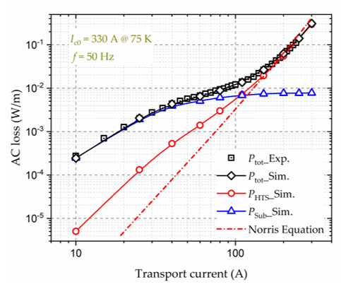
Figure 1. Variation of the AC loss of a 10 mm wide HTS CC with a magnetic substrate with sinusoidal transport currents. The self-field critical current, Ic0, of the HTS CC is 330 A at 75 K, and the frequency, f, of the AC magnetic field is 50 Hz. Experimental data are taken from
[16]. Inside electric machines, the electromagnetic environment is complicated, composed of abundant AC electromagnetic signals and high-frequency harmonics, especially for high-speed rotating machines. As a result, AC loss of superconductors becomes a key challenge for machine designs, in that not only does it affect the construction of cryocoolers and impair the efficiency of the system, but it also causes security hazards in case of quench (for superconducting coils) or demagnetization (for TFMs). The main concern regarding AC loss comes from armature windings
. Exp.-Experiment, Sim.-Simulation.
To overcome the limitations of the full models and decrease the modelling complexity, e.g., in the case of simulation of numerous HTS stacks or turns, some simplification approaches have been put forward, e.g., the homogenization method
[17]. To avoid high AC loss, a number of researchers have adopted partially superconducting machines, i.e., superconductors are only used as field sources by means of direct current (DC) carrying coils or TFMs, and armature windings are made of conventional conductors
, the multi-scaling approach
[18]
, and the densification method
[19]. However, it appears difficult for partially superconducting machines to achieve a power density higher than 20 kW/kg required for future aviation
. There exist other modelling methods for the calculation of AC loss, such as the integral equation method
[11]. Nowadays, targeted at high power superconducting machines for aircraft and aerospace applications, more and more researchers begin to focus on fully superconducting machines. As a result, AC loss of superconductors becomes inevitably one of the most challenging issues to be solved.
Figure 1 shows the AC loss per unit length of an example 12-mm-wide high-temperature superconductor (HTS) coated conductor (CC) and its filamentized tapes exposed to an externally applied AC magnetic field with an amplitude varying from 1 to 100 mT, at 40 Hz [20]. It can be seen that the AC loss of the HTS CC increases positively with the applied magnetic field, and for a CC without filaments, the power dissipation per unit length can attain 1 W/m even under a field as low as 20 mT at a low frequency of 40 Hz. The power is dissipated at cryogenic temperature, e.g., at liquid nitrogen temperature 77 K, which can constitute a big cryogenic burden. Table 1 presents the estimated heat load of HTS motors and generators employing different HTS materials at the operating temperature. To remove the heat load contributed by the AC loss, high cooling power is expected. Table 2 shows the ideal and practical Carnot specific power at a working temperature varying from 4.2 to 273 K. Carnot specific power is the quantity of watts needed at ambient temperature to offer 1 W of refrigeration at the lower working temperature
, and the Minimum Magnetic Energy Variation (MMEV) method
[21]. At present, commercially available refrigerators function far below the Carnot efficiency, i.e., their practical Carnot specific power is much higher than the ideal one, as shown in Table 2. According to Figure 1 and Table 1 and Table 2, it is not difficult to conclude that the heat load due to the AC loss of HTS materials applied to electrical machines proposes a big challenge for the design of cryogenic systems.
as well as Minimum Electro-Magnetic Entropy Production (MEMEP) method [22]. The integral equation method is based on the use of Green’s function to transform the partial differential equations into integral equations, which can avoid the meshing of non-conducting regions. As for the MMEV and MEMEP methods, they are computationally time-efficient and potentially promising for demanding 3D problems.
3.2. AC loss measurement approaches
There exist three main approaches for measuring AC loss of superconductors, namely electric, magnetic, and calorimetric methods.
The electric method is extensively used on account of its fast measurement speed and high sensitivity. It can be exploited to measure both AC transport current loss and magnetization loss, which consists of three types of techniques: the pick-up coil method, lock-in amplifier method, and the combination of the two techniques. Two typical electrical circuits of the pick-up coil method and the lock-in amplifier technique are presented in Figure 2.
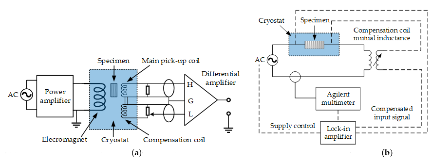
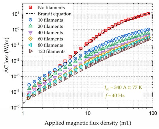
Figure 1. Variation of the AC loss of a 12-mm-wide YBCO CC and its filamentized tapes with externally applied AC magnetic fields. The self-field critical current, Ic0, of the YBCO CC is 340 A at 77 K, and the frequency, f, of the AC magnetic field is 40 Hz. Experimental data are from [20].
T2
. Typical electric circuits for the AC loss measurement. (
able 1. Estimated heat load of HTS machines at the working temperature
) Pick-up coil method, adapted from
Ta
. (
ble 2. Ideal and practical Carnot specific power at distinct working temperatures
) Lock-in amplifier technique, adapted from
| Working Temperature (K) | Ideal Carnot Specific Power (W) | Practical Carnot Specific Power (W) (When Heat Load > 100 W) |
|---|
45].
| Material | Unit Cost | Tc | Ic0 | ||
|---|---|---|---|---|---|
| Generators | 10–500 MW | 100–500 W at 25–40 K | 100–500 W at 50–65 K | ||
| 273 | 0.11 | 0.4 | |||
| REBCO (12 mm-width) | ~227 $/(kA·m) | Motors | 1–10 MW | 50–200 W at 25–40 K | 50–200 W at 50–65 K |
| 77 | 2.94 | 12–20 |
| 50 | 5.06 | 25–35 |
| 20 | 14.15 | 100–200 |
| 4.2 | 71.14 | 11,000 |
.
The AC loss of superconductors has been widely studied by many researchers; however, we have not seen a systematic review to summarize the advancements with respect to AC loss analysis during the last dozen years, especially combined with superconducting machines. Aiming to illuminate the state of the art of AC-loss-related research work and determine its future research trends in superconducting machine domains, we have conducted a comprehensive overview of AC-loss-related topics, including superconducting materials adopted in electrical machines, loss mechanism, and analytical formulae, modelling methods, measurement approaches, as well as loss reduction techniques. It should be pointed out that, as reported by our previous research work
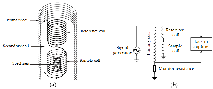
The magnetic method is regularly used to measure the hysteresis loss of superconductors. By measuring the voltages over pick-up coils around the superconducting specimen, which are then multiplied by the field strength and integrated over one cycle, the variation in the magnetic moment of the specimen can be identified
[22][23][24], the superconductors employed in high-speed rotating machines have to experience high-frequency electromagnetic environments. In this case, the total loss inside electrical machines is not purely contributed by the superconducting parts, but also by the normal conducting parts, due to the skin effect, which poses great challenges to the existing loss quantification and reduction techniques. Therefore, AC loss at high frequencies will be highlighted and discussed throughout the paper. This review work is believed to help researchers better understand the research status of AC loss in superconductors and to provide a useful reference for superconducting machine designs, especially for those functioning at high speeds for future aviation.
. The magnetic moment of the superconductor can be obtained with different methods, such as pick-up coils, Hall probes, superconducting quantum interference devices (SQUID), and vibrating-sample magnetometers (VSM). The measurement system is usually composed of the AC magnet, cryostat, pick-up coil, high-current amplifier, compensation coil, as well as the data acquisition system. Hysteresis loss can also be acquired through the measurement of the imaginary part of complex AC susceptibility. The equivalent circuit for a typical AC susceptibility measurement system is shown in Figure 3.
The disturbance of AC fields or currents is intrinsic in the electric and magnetic measurement approaches, which is not a concern for the calorimetric method. Besides, the reliability of the calorimetric method is not affected by the phase shift between the external field and the transport current. Therefore, the calorimetric method can be applied to a complicated electromagnetic environment. With the calorimetric method, the total AC loss can be obtained by the measurement of either the temperature rises of superconductors or the evaporated cryogen.
2. Superconducting Materials Applied to Electrical Machines
Superconducting materials can be categorized into low-temperature superconductors (LTSs), e.g., NbTi, and HTSs, e.g., REBCO (rare-earth barium copper oxide), and BSCCO (bismuth strontium calcium copper oxide), according to their critical temperature. For LTSs, their critical temperature is normally below 30 K. The unit cost, critical temperature, and current-carrying capacity of different materials are presented in Table 3. As for superconducting coils, nowadays most researchers in the applied superconductivity community concentrate on HTS CC-based coils because they can operate in liquid nitrogen (LN2) with a higher critical temperature in addition to a higher critical current and critical magnetic field. Certainly, HTS has a better current-carrying capacity if they operate at lower temperatures. The cost of commercial HTS materials, e.g., ~69 USD/m for a 12-mm-wide YBCO tape
Figure 3. Diagrams of the measurement systems for AC susceptibility of superconductors, adapted from
[25], is a primary factor limiting the development of HTS machines. With the advancement of processing techniques and material science, HTS materials are expected to have a lower cost in the near future. LTSs, in spite of having a worse current-carrying capacity compared to HTSs, have still been used in several designs because of their relatively lower material cost. However, they have to operate at liquid helium (LHe) or liquid hydrogen (LH2) temperature; thus, the cryogenic systems of LTS machines are generally more complicated and costly
: (a) Geometrical arrangement of different coils; (b) Equivalent circuit for the measurement system using the magnetic method.
To measure the temperature variation, cryogenic thermometers, cryostat, thermal isolation material, and voltage taps are usually needed. The calibration of the thermometers is the first step. Then, the variation of the thermal conductivity of the superconducting sample with temperature needs to be measured. Another temperature variation detection method is by optical fiber Bragg grating (FBG) [26], which takes advantage of the wavelength variance dependence of temperature.
The minimum measurable loss by the temperature rise measurement method is approximately 10-4 W/m. The measurement system using FBG is presented in Figure 4.
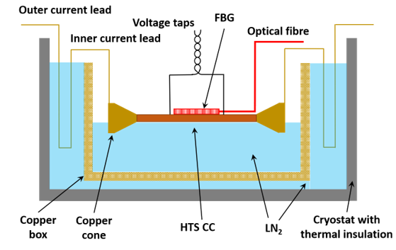
Figure 4. Diagram of the calorimetric measurement system based on the optical fiber Bragg grating for AC loss of HTS tapes, adapted from
[26]
.
The temperature rise due to dissipated energy will lead to the evaporation of the cryogen; thus, the measurement of AC loss can be achieved by measuring the gas flow volume of the evaporating cryogen, namely the boil-off method
[27]. Concerning AC loss, MgB2 possesses the advantage of a round wire compared with a flat tape; thus, it has the potential to become a low AC loss superconductor operating below 30 K
. The corresponding measurement system is mainly composed of the AC power supply, non-metal cryostat, cryogen, heat exchanger, thermostat, and gas flow meter. It should be noted that the measurement of cryogen evaporation is time-consuming and does not possess a high accuracy, with the minimum measurable loss of 10-4~10-2 W/m.
4. AC loss reduction techniques
The large cross-sectional aspect ratio of HTS CCs leads to a high magnetization loss; thus the striation of the HTS layer to a filamentary structure has been proposed to minimize the AC loss
[28]. Given this fact, many fully superconducting machine designs have adopted MgB2 coils as armature windings to avoid unbearable AC loss [29]
. Figure 5 demonstrates the measured magnetization loss of a 12-mm-wide YBCO CC with different filaments, in which the Brandt equation agrees well with the experimental data for the original HTS CC. It can be seen that the filamentation of HTS CCs can effectively decrease the AC loss, and the loss reduction effect gets enhanced with the increasing number of filaments. According to Equation (1), the magnetization loss is proportional to the square of the width of the HTS CC, thus a reduction by a factor N is expected if the HTS layer is striated to N filaments. However, this is true only at sufficiently high fields because at lower fields the superconductor volume penetrated by the field is larger in uncoupled filaments than in a nonstriated CC
[30]
and hence the loss of a filamentized CC can be greater than that of the original one, as shown in Figure 5. Different from conventional filamentary HTS CCs, a soldered-stacked-square wire has been proposed in
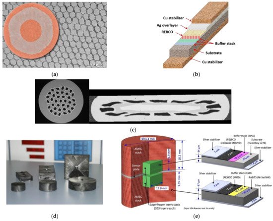
[31]. To maintain high electrical and magnetic loadings, while decreasing AC loss, multifilamentary HTS CCs have been implemented into electrical machines as an alternative [32]. The typical structure and composites of different superconductors can be found in Figure 2.
, which can help to decrease AC loss by 80% compared with originally uncut tapes.
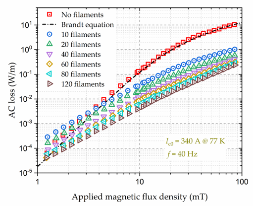
Figure 25. Diagrams of the superconductors applied to electrical machines: (a) Cross section of a NbTi wire (LTS). Illustration courtesy of Peter J. Lee, NHMFL; (b) Multilayer structure of an REBCO coated conductor (HTS); (c) Cross sections of round and flat MgB2 wires. Image courtesy of G. Grasso (© ASG Superconductors); (d) Photo of REBCO bulk superconductors, © evico GmbH; (e) Diagram of a trapped field HTS stack. Adapted from
Variation of the AC loss of a 12-mm-wide YBCO coated conductor (CC) and its filamentized tapes with externally applied AC magnetic fields. The self-field critical current, Ic0, of the YBCO CC is 340 A at 77 K, and the frequency, f, of the AC magnetic field is 40 Hz. Experimental data are from
.
3. Reported commercial superconductor specifications. Data are from
Another method to reduce the AC loss of HTS CCs is to change their physical arrangements, e.g., the Roebel concept, Rutherford cable, and Conductor on Round Core (CORC®) wire. Because of their periodically repeating and transposed physical properties, the twist structure can effectively reduce the transport current loss and magnetization loss compared with conventional HTS stacks, especially at medium-high currents and low magnetic fields [31]. The AC loss and inter-tape contact resistance of multiple cabling methods, including REBCO CORC®, Roebel, and stacked tape cables have been compared in [32]. It is found that the CORC® cable has lower hysteresis loss in an alternating magnetic field perpendicular to the wide side of the REBCO layer, compared with Roebel cables and non-twisted conductors.
In addition to the modifications to the physical structure of HTS CCs, the application of magnetic materials as flux diverters in electrical machines can also serve to decrease the AC loss of superconductors. According to the Jc(B) dependence, the field component perpendicular to the wide surface of an HTS CC has a greater impact on the critical current compared to the parallel component, and thus causes higher AC loss in the CC. An ideal flux diverter material exhibits high permeability; thus it can be applied to divert magnetic flux orientation to reduce the perpendicular field component and achieve the reduction of AC loss
.
Apart from the structure modification of superconductors and the application of ferromagnetic flux diverters, winding techniques are another effective way to decrease the AC losses of coils. A winding method for multilayer-type conductors composed of stacked Rutherford-type cables by controlling the twist angle around the conductor axis has been proposed in
[36]
, which can help decrease the total AC loss by 74% compared to the conventional winding method. Two auxiliary windings have been exploited in
[37]
to reduce the leakage flux in HTS transformers so that the AC loss of HTS coils can be decreased by about 13.6%. The optimization of the turn-to-turn resistivity can contribute to the reduction of AC loss, as reported in
. A shaped profile winding for minimal AC loss in conventional electrical machines has been reported in
[40]
, which maximizes slot area utilization to realize an improved low-speed and DC performance while achieving low AC loss. The proposed shaped profile winding technique possesses the potential to be adapted to superconducting windings. By orienting the CC or coil appropriately with respect to the external field, a substantial AC loss reduction can also be achieved
| up to 119 K | |||
| 400–600 A (SuperPower, 77 K) | |||
| REBCO (4 mm-width) | ~230 $/(kA·m) | up to 119 K | >100 A (SuperOX, 77 K) min. 88-min. 152 A (SuperPower, 77 K) min. 130 A (AMSC, enhanced pinning, 77 K) >165 A (Fujikura, 77 K) >150 A (SuNAM, 77 K) ~150 A (Shanghai SC, 77 K) >100 A (SWCC, 77 K) |
| Bi-2223 | 17.4 $/(kA·m) | 110 K | ~170–~200 A (SEI, 77 K) |
| NbTi (LTS) | 0.8 $/(kA·m) | 9.5 K | Up to 3 kA (SuperCon, 4.2 K) |
| MgB2 | 20 $/(kA·m) | 39 K | ~157 A (MgB2/Ga(30), 4.2 K) |
| NdFeB (PM) | 28.9 $/kg | / | / |
| Copper | 11.6 $/kg | / | / |
| Iron (Silicon steel) | 1.6 $/kg | / | / |
Tc critical temperature; Ic0—critical current in the self-field; PM—permanent magnet
TFMs consist of bulk superconductors and TFSs, most of which are manufactured by REBCO, despite the existence of MgB2 bulks. TFMs can give a magnetic field up to a significant degree higher contrasted with conventional PMs. Besides, different from electromagnets such as coils, no connection to a power supply is needed for TFMs. In 2014, Durrell et al. reported a trapped field of 17.6 T at 29 K in a stack of two silver doped GdBCO superconducting bulk samples [46]. A record-high trapped field of 16.1 T in MgB2 bulk has been recently achieved at 20 K by Hirano et al. using pulsed-field magnetization (PFM) [47]. The possibility of the application of bulk superconductors to electrical machines has been discussed by many researchers. Kurbatova et al. have presented an electromagnetic analysis of an electrical generator equipped with HTS bulks on the rotor and revealed that the generator performance depends on the HTS properties and the parameters of the magnetization [48]. Izumi et al. have developed an axial-gap-type synchronous machine utilizing GdBCO bulks as field poles, which is meant for low-speed ship propulsion [49]. Bulk superconductors can also serve as lightweight and compact magnetic shields in electrical machines, as reported by Leveque et al. [50]. However, a pivotal disadvantage of bulk superconductors lies in their thermal instability at low temperatures, making it hard to exploit the high critical current under 30 K [51]. In addition, external mechanical support is required in the utilization of bulk superconductors on account of their restricted mechanical strength. Compared with bulk superconductors, TFSs have better thermal stability and mechanical strength on the grounds that the copper stabilizers and silver overlayer of REBCO CCs have a thermal conductivity over a significant degree higher than REBCO, and the Hastelloy substrate has a more grounded tensile strength contrasted with REBCO. A trapped field of 17.7 T at 8 K in a stack of HTS tapes was reported by Patel et al. in 2018 [34]. The application of TFSs as field poles to a 1 MW superconducting demonstrator motor is being explored in the EU project ASuMED [14]. As mentioned in [52], in terms of the energization method, TFMs can avoid the application of current leads during operation compared to DC superconducting coils. However, the maximum size of TFMs can be limited by the existing production technology, especially for TFSs, and they can experience a possible demagnetization under cross fields [53], bringing a threat to the safe operations of superconducting electrical machines.
.
5. Conclusions
This entry has presented multiple AC loss related topics: AC loss mechanism and analytical formulae, modelling methods, measurement approaches, as well as loss minimization techniques. It has provided a useful reference for loss quantification and loss controlling in Type-II superconductors and delivered a helpful guideline for future research efforts.
References
- Lei, G.; Zhu, J.; Guo, Y.; Liu, C.; Ma, B. A Review of Design Optimization Methods for Electrical Machines. Energies 2017, 10, 1962.F. Grilli and F. Sirois (2016). AC Losses and Numerical Modeling of Superconductors. In digital Encyclopedia of Applied Physics, Wiley‐VCH Verlag GmbH & Co. KGaA (Ed.). https://doi.org/10.1002/3527600434.eap770.
- Wildi, T. Electrical Machines Drives and Power Systems; Prentice-Hall: Englewood Cliffs, NJ, USA, 2005.M. D. Ainslie (2012). Transport AC loss in high temperature superconducting coils (Doctoral thesis). https://doi.org/10.17863/CAM.14029.
- Saidur, R. A review on electrical motors energy use and energy savings. Renew. Sustain. Energy Rev. 2010, 14, 877–898.Z. Jiang et al, "Dynamic resistance of a high-Tc coated conductor wire in a perpendicular magnetic field at 77 K", Supercond. Sci. Technol., vol. 30, no. 3, 03LT01, 2017.
- Hossain, M.S. Panel estimation for CO2 emissions, energy consumption, economic growth, trade openness and urbaniza-tion of newly industrialized countries. Energy Policy 2011, 39, 6991–6999.M. R. Halse, "AC face field losses in a type II superconductor", J. Phys. D Appl. Phys., vol. 3, no. 5, pp. 717-720, 1970.
- Cheng, M.; Sun, L.; Buja, G.; Song, L. Advanced Electrical Machines and Machine-Based Systems for Electric and Hybrid Vehicles. Energies 2015, 8, 9541–9564.E. H. Brandt and M. Indenbom, "Type-II superconductor strip with current in a perpendicular magnetic field," Phys. Rev. B, vol. 48, no. 17, pp. 12893–12906, 1993.
- Cheng, M.; Zhu, Y. The state of the art of wind energy conversion systems and technologies: A review. Energy Convers. Manag. 2014, 88, 332–347.W. T. Norris, "Calculation of hysteresis loss in hard superconductors carrying ac: isolated conductors and edges of thin sheets, " J. Phys. D: Appl. Phys., vol. 3, pp. 489–507, 1969.
- Wrobel, R.; Mecrow, B.C. A Comprehensive Review of Additive Manufacturing in Construction of Electrical Machines. IEEE Trans. Energy Convers. 2020, 35, 1054–1064.H. Zhang, et al., "A full-range formulation for dynamic loss of HTS coated conductors," Supercond. Sci. Technol., vol. 33, no. 5, 05LT01, 2020.
- Li, S.; Zhang, S.; Habetler, T.G.; Harley, R.G. Modeling, Design Optimization, and Applications of Switched Reluctance Machines—A Review. IEEE Trans. Ind. Appl. 2019, 55, 2660–2681.J. Rhyner, "Magnetic properties and AC-losses of superconductors with power law current-voltage characteristics," Physica C, vol. 212, pp. 292–300, 1993.
- Lee, D.; Park, G.; Son, B.K.; Jung, H. Efficiency improvement of IPMSG in the electric power generating system of a range-extended electric vehicle. IET Electr. Power Appl. 2019, 13, 943–950.Y. B. Kim, C. F. Hempstead, and A. R. Strnad, "Critical persistent currentsin hard superconductors," Phys. Rev. Lett., vol. 9, no. 7, pp. 306–309, 1963.
- Sun, X.; Shi, Z.; Lei, G.; Guo, Y.; Zhu, J. Analysis and Design Optimization of a Permanent Magnet Synchronous Motor for a Campus Patrol Electric Vehicle. IEEE Trans. Veh. Technol. 2019, 68, 10535–10544.P. W. Anderson, "Theory of flux creep in hard superconductors," Phys. Rev. Lett., vol. 9, no. 7, pp. 309–311, 1963.
- Sahoo, S.; Zhao, X.; Kyprianidis, K. A Review of Concepts, Benefits, and Challenges for Future Electrical Propulsion-Based Aircraft. Aerospace 2020, 7, 44.G. P. Mikitik and E. H. Brandt, "Generation of a dc voltage by an ac magnetic field in type-II superconductors," Phys. Rev. B, vol. 64, 092502, 2001.
- Jlassi, I.; Cardoso, A.J.M. Fault-Tolerant Back-to-Back Converter for Direct-Drive PMSG Wind Turbines Using Direct Torque and Power Control Techniques. IEEE Trans. Power Electron. 2019, 34, 11215–11227.H. Zhang, et al., "Alternating current loss of superconductors applied to superconducting electrical machines," Energies, vol. 14, no. 8, pp. 2234. 2021.
- Taherian-Fard, E.; Sahebi, R.; Niknam, T.; Izadian, A.; Shasadeghi, M. Wind Turbine Drivetrain Technologies. IEEE Trans. Ind. Appl. 2020, 56, 1729–1741.H. Zhang et al., "Modelling of electromagnetic loss in HTS coated conductors over a wide frequency band", Supercond. Sci. Technol., vol. 33, no. 2, 025004, 2020.
- Grilli, F.; Benkel, T.; H¨anisch, J.; Lao, M.; Reis, T.; Berberich, E.; Wolfst¨adter, S.; Schneider, C.; Miller, P.; Palmer, C.; et al. Superconducting motors for aircraft propulsion: The Advanced Superconducting Motor Experimental Demonstrator project. J. Phys. Conf. Ser. 2020, 1590, 012051.H. Zhang, et al., "Dynamic loss and magnetization loss of HTS coated conductors, stacks, and coils for high-speed synchronous machines," Supercond. Sci. Technol., vol. 33, no. 8, 084008, 2020.
- Haran, K.S.; Kalsi, S.; Arndt, T.; Karmaker, H.; Badcock, R.; Buckley, B.; Haugan, T.; Izumi, M.; Loder, D.; Bray, J.W.; et al. High power density superconducting rotating machines—development status and technology roadmap. Supercond. Sci. Technol. 2017, 30, 123002.F. Grilli et al, "Computation of Losses in HTS Under the Action of Varying Magnetic Fields and Currents," IEEE Trans. Appl. Supercond., vol. 24, no. 1, pp. 78-110, 2014.
- Ainslie, M.D.; Bumby, C.W.; Jiang, Z.; Toyomoto, R.; Amemiya, N. Numerical modelling of dynamic resistance in high-temperature superconducting coated-conductor wires. Supercond. Sci. Technol. 2018, 31, 074003.D. N. Nguyen et al., "A new finite-element method simulation model for computing AC loss in roll assisted biaxially textured substrate YBCO tapes”, Supercond. Sci. Technol., vol. 23, 025001, 2009.
- Feddersen, M.; Haran, K.S.; Berg, F. AC Loss Analysis of MgB2-Based Fully Superconducting Machines. IOP Conf. Ser. Mater. Sci. Eng. 2017, 279, 012026.V. M. R. Zermeno, A. B. Abrahamsen, N. Mijatovic, B. B. Jensen and M. P. Soerensen, "Calculation of AC losses in stacks and coils made of second generation high temperature superconducting tapes for large scale applications", J. Appl. Phys., vol. 114, no. 17, pp. 173901-1-173901-9, 2013.
- Fair, R.; Lewis, C.; Eugene, J.; Ingles, M. Development of an HTS hydroelectric power generator for the hirschaid power station. J. Phys. Conf. Ser. 2010, 234, 032008.V. M. R. Zermeno et al., "Towards Faster FEM Simulation of Thin Film Superconductors: A Multiscale Approach," IEEE Trans. Appl. Supercond., vol. 21, no. 3, pp. 3273-3276, 2011.
- Corduan, M.; Boll, M.; Bause, R.; Oomen, M.P.; Filipenko, M.; Noe, M. Topology Comparison of Superconducting AC Machines for Hybrid Electric Aircraft. IEEE Trans. Appl. Supercond. 2020, 30, 1–10.E. Berrospe-Juarez, F. Trillaud, V. Zermeno, and F. Grilli, "Advanced electromagnetic modeling of large-scale high temperature superconductor systems based on H and T-A formulations", Supercond. Sci. Technol., vol. 34, no. 4, 044002, 2021.
- Demencik, E.; Vojenciak, M.; Kario, A.; Nast, R.; Jung, A.; Goldacker, W.; Grilli, F. AC Loss and Coupling Currents in YBCO Coated Conductors With Varying Number of Filaments. IEEE Trans. Appl. Supercond. 2014, 24, 1–8.R. Brambilla, F. Grilli, L. Martini, and F. Sirois, "Integral equations for the current density in thin conductors and their solution by finite element method," Supercond. Sci. Technol., vol. 21, no. 10, 105008, 2008.
- Grilli, F.; Pardo, E.; Stenvall, A.; Nguyen, D.N.; Yuan, W.; Gomory, F. Computation of Losses in HTS Under the Action of Varying Magnetic Fields and Currents. IEEE Trans. Appl. Supercond. 2014, 24, 78–110.E. Pardo et al, "Current distribution and ac loss for a superconducting rectangular strip with in-phase alternating current and applied field," Supercond. Sci. Technol., vol. 20, no. 4, pp. 351–364, 2007.
- Zhang, H.; Yao, M.; Kails, K.; Machura, P.; Mueller, M.; Jiang, Z.; Xin, Y.; Li, Q. Modelling of electromagnetic loss in HTS coated conductors over a wide frequency band. Supercond. Sci. Technol. 2019, 33, 025004.E. Pardo, J. Souc, and L. Frolek, "Electromagnetic modelling of superconductors with a smooth current-voltage relation: Variational principle and coils from a few turns to large magnets," Supercond. Sci. Technol., vol. 28, no. 4, 044003, 2015.
- Zhang, H.; Machura, P.; Kails, K.; Chen, H.; Mueller, M. Dynamic loss and magnetization loss of HTS coated conductors, stacks, and coils for high-speed synchronous machines. Supercond. Sci. Technol. 2020, 33, 084008.S. Kawabata et al, "Standardization of the pickup coil method for AC loss measurement of three-component superconducting wires," Physica C Supercond, vol. 392–396, Part 2, pp. 1129-1133, 2003.
- Kails, K.; Zhang, H.; Machura, P.; Mueller, M.; Li, Q. Dynamic loss of HTS field windings in rotating electric machines. Supercond. Sci. Technol. 2020, 33, 045014.Oomen, M.P. AC Loss in Superconducting Tapes and Cables. Ph.D. Thesis, University of Twente, Enschede, The Netherlands, 2000. Available online: https://www.elibrary.ru/item.asp?id=5312717. (accessed on 20 December 2020).
- Miura, S.; Iwakuma, M.; Izumi, T. Lightweight Design of Tens-MW Fully-Superconducting Wind Turbine Generators With High-Performance REBa 2 Cu 3 O y Wires. IEEE Trans. Appl. Supercond. 2020, 30, 9028170.University of Florida-Department of Physics, PHY4803L-Advanced Physics Laboratory. AC Susceptibility Measurements in High-Tc Superconductors. Available online: https://www.phys.ufl.edu/courses/phy4803L/group_II/high_Tc/hightc.pdf. (accessed on 20 December 2020).
- Stautner, W. Cryocoolers for Superconducting Generators. In Thermal Properties of Solids at Room and Cryogenic Temperatures; Metzler, J.B., Ed.; Springer: Berlin/Heidelberg, Germany, 2020; pp. 121–154.J. S. Dai et al, "A novel calorimetric method for measurement of AC losses of HTS tapes by optical fiber Bragg grating," 2013 IEEE International Conference on Applied Superconductivity and Electromagnetic Devices, Beijing, 2013, pp. 124-127.
- Sun, J.; Neumann, H.; Sanz, S.; Sarmiento, G.; Tropeano, M.; Marino, I.; Pujana, A.; Merino, J.M. Design and Construction of the Cryogenic Cooling System for the Rotating Magnetic Validator of the 10 MW SUPRAPOWER Offshore Superconducting Wind Turbine. IEEE Trans. Appl. Supercond. 2018, 28, 1–5.C. H. Jones and H. L. Schenk, "A.C. losses in hard superconductors" Advances in Cryogenic Engineering, New York: Plenum, vol. 8, pp. 579-584, 1963.
- Tomsic, M.; Rindfleisch, M.; Yue, J.; McFadden, K.; Phillips, J.; Sumption, M.D.; Bhatia, M.; Bohnenstiehl, S.; Collings, E.W. Overview of MgB2Superconductor Applications. Int. J. Appl. Ceram. Technol. 2007, 4, 250–259.N. Amemiya et al., "AC loss reduction of YBCO coated conductors by multifilamentary structure", Supercond. Sci. Technol., vol. 17, no. 12, pp. 1464-1471, 2004.
- Nam, G.-D.; Sung, H.-J.; Go, B.-S.; Park, M.; Yu, I.-K. Design and Comparative Analysis of MgB2 and YBCO Wire-Based-Superconducting Wind Power Generators. IEEE Trans. Appl. Supercond. 2018, 28, 1–5.F. Grilli and A. Kario, "How filaments can reduce AC losses in HTS coated conductors: A review", Supercond. Sci. Technol., vol. 29, no. 8, 083002, 2016.
- Lin, F.; Qu, R.; Li, D.; Cheng, Y.; Sun, J. Electromagnetic Design of 13.2 MW Fully Superconducting Machine. IEEE Trans. Appl. Supercond. 2018, 28, 1–5.E. Demenčík et al., "AC Loss and Coupling Currents in YBCO Coated Conductors With Varying Number of Filaments," IEEE Trans. Appl. Supercond, vol. 24, no. 6, pp. 1-8, 2014.
- Song, X.; Mijatovic, N.; Jensen, B.B.; Holboll, J. Design Study of Fully Superconducting Wind Turbine Generators. IEEE Trans. Appl. Supercond. 2015, 25, 1–5.M. Wang, M. Zhang, M. Song and Z. Li, "An effective way to reduce AC loss of second-generation high temperature superconductors", Supercond. Sci. Technol., vol. 32, 01LT01, 2019.
- Saruwatari, M.; Yun, K.; Iwakuma, M.; Tamura, K.; Hase, Y.; Sasamori, Y.; Izumi, T. Design Study of 15-MW Fully Superconducting Generators for Offshore Wind Turbine. IEEE Trans. Appl. Supercond. 2016, 26, 1–5.W. Goldacker et al., "Roebel cables from REBCO coated conductors: A one-century-old concept for the superconductivity of the future", Supercond. Sci. Technol., vol. 27, no. 9, 093001, 2014.
- Patel, A.; Baskys, A.; Mitchell-Williams, T.B.; McCaul, A.; Coniglio, W.; Haenisch, J.; Lao, M.L.; A Glowacki, B. A trapped field of 17.7 T in a stack of high temperature superconducting tape. Supercond. Sci. Technol. 2018, 31, 09LT01.K Yagotintsev et al, "AC loss and contact resistance in REBCO CORC®, Roebel, and stacked tape cables", Supercond. Sci. Technol., vol. 33, 085009, 2020.
- Gomory, F.; Souc, J.; Pardo, E.; Seiler, E.; Soloviov, M.; Frolek, L.; Skarba, M.; Konopka, P.; Pekarčíková, M.; Janovec, J. AC Loss in Pancake Coil Made From 12 mm Wide REBCO Tape. IEEE Trans. Appl. Supercond. 2013, 23, 5900406.F. Gömöry, M. Vojenciak, E. Pardo and J. Souc, "Magnetic flux penetration and AC loss in a composite superconducting wire with ferromagnetic parts", Supercond. Sci. Technol., vol. 22, 034017, 2009.
- Hayashi, K. Commercialization of Bi-2223 Superconducting Wires and Their Applications. Sei Tech. Rev. 2020, 91, 68–74. Available online: (accessed on 10 January 2021).M. D. Ainslie et al, "Numerical Analysis of AC Loss Reduction in HTS Superconducting Coils Using Magnetic Materials to Divert Flux," IEEE Trans. Appl. Supercond., vol. 23, no. 3, pp. 4700104-4700104, 2013.
- Ku, M.-H.; Kang, M.-H.; Lee, H.-J.; Cha, G.-S. The Critical Current Characteristics and n-value Measurement of HTS Tapes. Pro-gress Supercond. Cryog. 2010, 12, 12–16.A. Kawagoe, F. Sumiyoshi, M. Nakanishi, T. Mito and T. Kawashima, "A new winding method to reduce AC losses in stable LTS pulse coils," IEEE Trans. Appl. Supercond, vol. 13, no. 2, pp. 2404-2407, 2003.
- Ishmael, S.A.; Rogers, S.; Hunte, F.; Naderi, G.; Roach, C.; Straka, W.; Schwartz, J. Current Density and Quench Behavior of MgB 2/Ga Composite Wires. IEEE Trans. Appl. Supercond. 2015, 25, 1–8.H. Heydari et al, "New approach for AC loss reduction in HTS transformer using auxiliary windings case study: 25 kA HTS current injection transformer", Supercond. Sci. Technol., vol. 21, no. 1, 015009, 2008.
- Park, M. Realization of a Large-Scale Superconducting Generator for a Wind Power Generation System; ESAS Summer School on HTS Technology for Sustainable Energy and Transport System. Available online: (accessed on 20 December 2020).J. M. Kim et al, "Investigation about the effects of metal-clad winding on the electromagnetic characteristics of the GdBCO racetrack coils in a time-varying magnetic field," Results in Physics, vol. 11, pp. 400-405, 2018.
- Haught, D. Recent HTS activities in the US. In Proceedings of the IEA HTS Executive Committee Meeting, Milan, Italy, 19 June 2014; pp. 1–47. Available online: (accessed on 20 December 2020).Y. Wang et al., "No-Insulation High-Temperature Superconductor Winding Technique for Electrical Aircraft Propulsion," IEEE Trans. Transp. Electrification, vol. 6, no. 4, pp. 1613-1624, 2020.
- Yagai, T.; Mizuno, S.; Okubo, T.; Mizuochi, S.; Kamibayashi, M.; Jimbo, M.; Takao, T.; Hirano, N.; Makida, Y.; Shintomi, T.; et al. Development of design for large scale conductors and coils using MgB2 for superconducting magnetic energy storage device. Cryogenics 2018, 96, 75–82.N. Simpson et al, "Additive Manufacturing of Shaped Profile Windings for Minimal AC Loss in Electrical Machines," IEEE Trans. Ind. Appl., vol. 56, no. 3, pp. 2510-2519, 2020.
- Elsherif, M.; Taylor, P.; Blake, S. Investigating the potential impact of superconducting distribution networks. In Proceedings of the 22nd International Conference and Exhibition on Electricity Distribution (CIRED 2013), Stockholm, Sweden, 10–13 June 2013; p. 816.Z. Jiang et al, "15% reduction in AC loss of a 3-phase 1 MVA HTS transformer by exploiting asymmetric conductor critical current," J. Phys. Commun., vol. 5, 025003, 2021.
- Rammah, Y.; Salama, A.; Elkhatib, M. Magnetic Moment and its Correlation with the Critical Temperature in YBCO. Int. Ceram. Rev. 2019, 68, 34–41.
- Tsuchiya, K.; Kikuchi, A.; Terashima, A.; Norimoto, K.; Uchida, M.; Tawada, M.; Masuzawa, M.; Ohuchi, N.; Wang, X.; Takao, T.; et al. Critical current measurement of commercial REBCO conductors at 4.2 K. J. Cryog. 2017, 85, 1–7.
- Jensen, B.B.; Mijatovic, N.; Abrahamsen, A.B. Development of superconducting wind turbine generators. J. Renew. Sustain. Energy 2013, 5, 23137.
- Bykovskiy, N.; Kaal, S.; Dudarev, A.; Mentink, M.; Kate, H.H.J.T. Demonstration of engineering current density exceeding 1 kA mm−2 in ultra-thin no-insulation, soldered coil windings using NbTi/Cu wires with CuNi cladding. Supercond. Sci. Technol. 2020, 33, 114001.
- Durrell, J.H.; Dennis, A.R.; Jaroszynski, J.; Ainslie, M.D.; Palmer, K.G.B.; Shi, Y.-H.; Campbell, A.M.; Hull, J.R.; Strasik, M.; E Hellstrom, E.; et al. A trapped field of 17.6 T in melt-processed, bulk Gd-Ba-Cu-O reinforced with shrink-fit steel. Supercond. Sci. Technol. 2014, 27, 082001.
- Hirano, T.; Takahashi, Y.; Namba, S.; Naito, T.; Fujishiro, H. A record-high trapped field of 1.61 T in MgB2 bulk comprised of copper plates and soft iron yoke cylinder using pulsed-field magnetization. Supercond. Sci. Technol. 2020, 33, 085002.
- Kurbatova, E.; Kurbatov, P.; Dergachev, P.; Molokanov, O. Electromagnetic Analysis of HTS Generator with Bulk Superconductor. In 2018 20th International Symposium on Electrical Apparatus and Technologies (SIELA); Institute of Electrical and Electronics Engineers (IEEE): New York, NY, USA, 2018; pp. 1–4.
- Zhang, Y.; Zhou, D.; Ida, T.; Miki, M.; Izumi, M. Melt-growth bulk superconductors and application to an axial-gap-type rotating machine. Supercond. Sci. Technol. 2016, 29, 044005.
- Colle, A.; Lubin, T.; Ayat, S.; Gosselin, O.; Leveque, J. Analytical Model for the Magnetic Field Distribution in a Flux Modulation Superconducting Machine. IEEE Trans. Magn. 2019, 55, 1–9.
- Patel, A.; Filar, K.; Nizhankovskii, V.I.; Hopkins, S.C.; Glowacki, B.A. Trapped fields greater than 7 T in a 12 mm square stack of commercial high-temperature superconducting tape. Appl. Phys. Lett. 2013, 102, 102601.
- Patel, A.; Climente-Alarcon, V.; Baskys, A.; A Glowacki, B.; Reis, T. Design considerations for fully superconducting synchronous motors aimed at future electric aircraft. In Proceedings of the 2018 IEEE International Conference on Electrical Systems for Aircraft, Railway, Ship Propulsion and Road Vehicles & International Transportation Electrification Conference (ESARS-ITEC), Railway, Nottingham, UK, 7–9 November 2018; Institute of Electrical and Electronics Engineers (IEEE): New York, NY, USA, 2018; pp. 1–6.
- Kapolka, M.; Pardo, E.; Grilli, F.; Baskys, A.; Climente-Alarcon, V.; Dadhich, A.; A Glowacki, B. Cross-field demagnetization of stacks of tapes: 3D modelling and measurements. Supercond. Sci. Technol. 2019, 33, 044019.