 +1 credit
| Version | Summary | Created by | Modification | Content Size | Created at | Operation |
|---|---|---|---|---|---|---|
| 1 | Jo-Chun Kim | + 3124 word(s) | 3124 | 2021-01-14 08:55:20 | | | |
| 2 | Lily Guo | -40 word(s) | 3084 | 2021-01-21 03:36:06 | | | | |
| 3 | Lily Guo | + 483 word(s) | 3567 | 2021-01-25 07:27:00 | | | | |
| 4 | Lily Guo | + 483 word(s) | 3567 | 2021-01-25 07:31:09 | | |
Video Upload Options
A continuous emission monitoring system (CEMS) is a well-known tool used to analyze the concentrations of air pollutants from stationary sources. In a CEMS, the presence of a high moisture level in a sample causes a loss of analytes due to artifact formation or absorption. This issue brings about a bias in the measurement data. Thus, moisture removal is an important pretreatment step.
1. The importance of moisture removal devices for a continuous monitoring system
The continuous emission monitoring system (CEMS) has been applied to monitor the air pollutants emitted from stationary sources. An extractive method, in which air pollutants are delivered to analyzers located in a shelter, and an in situ method, in which analyzers are attached directly to an emission stack, are used for the CEMS . The CEMS is usually applied to detect the emissions of air pollutants such as carbon monoxide (CO), carbon dioxide (CO2), sulfur oxides (SOx), nitrogen oxides (NOx), hydrogen chloride (HCl), hydrogen fluoride (HF), ammonia (NH3), water vapor (H2O), particulate matter, etc. Spectroscopy analyzers have been widely installed in CEMS due to the advantage of continuous monitoring and good accuracy. As a spectroscopy analyzer, nondispersive infrared (NDIR) and Fourier transform infrared analyzers have been widely used because they operate consistently with low energy consumption compared to other spectroscopy technologies[1]. However, moisture (H2O) in the gas stream is a significant interference since it affects the accuracy of the NDIR analyzer [2]. Moisture can cause a bias of the NDIR analyzer up to 30% for NO2 (i.e., at a wavelength of 6.21 µm), 20% for SO2 (i.e., at a wavelength of 7.45 µm), and 5% for NO (i.e., at a wavelength of 5.25 µm) [3]. For particulate matter, the particle concentration can be monitored by light scattering analyzers (e.g., optical particle counter or condensation particle counter)[4][5][6][7][8], light absorption analyzers (e.g., spot meters, aethalometer, photoacoustic soot sensor, or laser-induced incandescence)[4][5][9], light extinction analyzers (e.g., cavity ring-down or opacity meter)[4][5][10][11] and microbalance analyzers (e.g., tapered element oscillation microbalance or quartz crystal microbalance)[4][5][12]. Size distributions of particles can be continuously determined using a fast-mobility particle sizer and an electric low-pressure impactor [4][5][13][14][15]. Among these methods, light-scattering meters, opacity meters, Beta attenuation meters, and electrification devices have been widely applied for CEMS[16][17]. However, H2O has a significant effect on the light-scattering method used to measure particulate matter[17][18][19][20]. It was found that light-scattering ratios of sodium chloride particles increased from 1- to 10-fold when the relative humidity increased from 20% to 80%. On the other hand, these values for uranine dye particles were increased 1–2-fold due to their lower hygroscopicity[17]. Zieger et al. (2013) found that light-scattering ratios were increased approximately 5-, 7-, 9-, and 16-fold with respect to (NH4)2SO4, NaNO3, Na2SO4, and H2SO4 particles, respectively, at 85% relative humidity and a 589 nm wavelength[18]. It was also found that the number of particles increased by approximately 50%, and the PM10 concentration increased by as much as 46% when the experiment was conducted at 75% relative humidity[19][19]. For electrification devices, wet gas streams had significant effects on the probe electrification[16]. It is now well known that the moisture content in the flue gas is high, as shown in Table 1. The United States Environmental Protection Agency (U.S. EPA) stated that moisture is one of the significant bias sources for extractive CEMS[21]. Moisture causes effects such as the absorption of water-soluble gases or artifact formation. For artifact formation in the presence of moisture, HCl may react with NH3 to produce ammonium chloride salt [22]. In a municipal waste incinerator, NH3 was found to react with HCl or SO2 to create ammonia salts such as ammonium chloride or ammonium sulfite[23]. For the absorption, a negative measurement bias for NH3 was found due to condensation[23]. Thirty percent of 10 ppmv SO2 was found to be lost at 20% absolute humidity [21]. The condensed water could also corrode the system and cause a leak[21]. In combination with particles in the gas stream, mud could form and plug the system [21]. Hence, moisture removal is an important issue for extractive CEMS.
|
Emission Source |
Temperature (°C) |
Humidity (vol%) |
|
72 |
5.6–10 |
|
|
Heating station[26] |
150 |
0.9 |
|
Basic oxygen furnace[25] |
54 |
5.7 |
|
79–150 |
0.7–5.1 |
|
|
Electric arc furnace[25] |
86.7 |
4.2 |
|
Heavy oil plant[25] |
247 |
7.3 |
|
Cement (drying)[25] |
103 |
19.4 |
|
Cement (pryo-processing) [25] |
142 |
3.5 |
|
Boiler (heavy oil fuel)[27] |
310 |
10 |
|
100–177 |
0.9–8.7 |
|
|
Hazardous waste incinerator[22] |
– |
50 |
|
Portland cement kiln[22] |
– |
10–35 |
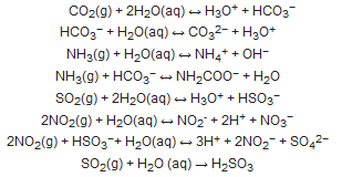
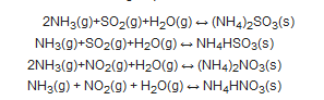
Reactions and dissociations of several analytes may occur in two ways as follows [30][31][32][33][34]:
In the first case, moisture is condensed as liquid droplets:
To reduce the effect of water vapor, three methods have been used to date. In the first method, both extractive sampling lines and the gas cells of analyzers are heated to prevent water vapor from forming condensation. The high energy consumption caused by a heater is a disadvantage of this method. In addition, air pollutants in contact with a high-energy light source in the analyzer such as UV or IR can cause reactions among the pollutants. Another disadvantage of the method is the measurement bias because of the sample temperature [22]. It was found that the HCl measurement results involved a negative bias when the sample temperature was lower than the stack temperature. In contrast, when the sample temperature was higher than the stack temperature, particulate ammonium chloride might volatilize to produce HCl and NH3, which brought about a positive measurement bias for HCl and NH3 [22]. The second method involves the dilution of flue gas to reduce the concentration of water. However, dilution factors are dependent on the detection limit of the gas analyzer. Therefore, this method requires highly sensitive analyzers that increase the cost of the CEMS. The third method, which has been popularly employed, is the cool/dry method. In this approach, moisture in the flue gas is removed using a moisture removal system. The removal of moisture from the flue gas helps to reduce the energy consumption of a heater, the interference of target compound detection, and artifact formation. Due to the high concentration of moisture in the gas stream emitted from a stack, two types of moisture removal methods are commonly used: condensation and permeation[35]. Condensation processes are generally classified into homogeneous and heterogeneous condensation [36]. In homogeneous condensation, a liquid droplet embryo is formed within the supercooled vapor. On the other hand, in heterogeneous condensation, liquid droplet nucleation occurs at the interface of another phase (e.g., a cold solid wall or particle) at a low temperature[36]. For the permeation method, permeation membranes are divided into dense (i.e., pores of ~0.1 nm) and porous (i.e., pores of ~0.1 µm) types[36]. However, an ideal method has not yet been invented since each of these has limitations [21].
Although moisture removal is an important issue in CEMS, scientific research into this topic is lacking. Almost all moisture removal technologies are presented as patents and commercial products. However, many studies have been carried out on moisture control for other processes such as air conditioning[37][38][39][40][41][42][43], chemical analysis[44][45][46][47][48][49][50][51], clothes drying [52][53][54][55][56], gas turbines[57][58][59] , and laundering [60][61][62]. Consequently, in this communication, condensation methods, which are used to remove moisture for a extractive CEMS, were introduced.
2. An overview on moisture removal devices using condensation technique in a CEMS
On the basis of water physical properties, the temperature of the flue gas in the extractive line was reduced below the dew point to condense the water vapor. The condensation system must be suitable for the flow rate and moisture concentration of the sample gas. Moreover, the structure of the system must avoid contact between the condensed water and the dried flue gas. To decrease the temperature of the gas stream, two technologies have generally been employed: refrigeration using a coolant and Peltier.
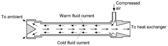
The typical structure of a refrigerated system is shown in Figure 1. On the basis of this principle, several apparatuses have been developed. Dowling (1980) invented a moisture removal system based on the refrigerated method with an improvement to the air-to-air and air-to-refrigerant heat exchanger [63]. The exchanger consists of a bundle of vertical tubing in a housing (Figure 2). Parallel sheet metal fins are used to hold the tubing. Moisture is condensed and deposited on the sheet and then drips down the bottom of the housing due to gravity. The advantage of this system is the absence of the water separator. Moreover, the fin sheets help to increase the turbulence of the air and liquid flow, which protects the surface of the sheet to stave off fouling [63]. Nanaumi and Baba (1980) also improved the heat exchanger for the refrigerated system [64]. The main novelty of this invention is the use of an extra heat exchanger to cover the heat exchanger of the refrigerated system to precool the inlet air [64]. These two inventions improved the cooling efficiency, which helped to remove more moisture with respect to a high loading capacity. The principle of both inventions is heterogeneous condensation. The moisture was removed under liquid phase, and most of the droplets were condensed on the cold surface of a device. Thus, the loss of highly water-soluble compounds would occur.
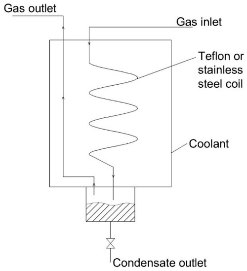
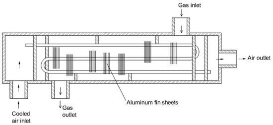
Figure 2. Structure of an air-to-air heat exchanger[63].
A two-stage moisture removal system was developed by Basseen et al. (1988)[65]. First, the inlet air was precooled to −40 °C using a refrigerator to reduce the air temperature and remove some of the moisture. The flue gas was continued, introducing it to the second stage, which consists of dual desiccant beds to adsorb the remaining moisture content. These beds are alternatively working and regenerating. The system can reduce the humidity from about 15% to 1%[65]. In this invention, the moisture is also condensed by way of a heterogeneous process. The phase of water is solid, which is suitable for highly water-soluble compounds. Due to the two stages of moisture removal, the device can operate at high moisture loading. Moreover, the moisture removal efficiency of the device is also high. However, a desiccant could adsorb certain compounds, which affected the selectivity of the device.
In particular, Tosi (2009) used a vortex tube to cool the flue gas to the dew point temperature[66]. In the tube, the vortical motion of air at high speed (i.e., a moving hot stream with a different direction to that of the cold stream) induced cold air, which was introduced to the heat exchanger to reduce the temperature of the inlet gas (Figure 3)[66]. The condensation of water vapor is a homogeneous process in this case. The advantage of this system is its low energy consumption compared to a refrigerated technology. However, due to the direct contact with condensed water in a heat exchanger, water-soluble gases can be absorbed in water, which might affect the accuracy of the analytical results.
The advantages of the refrigeration-based method are the high cooling efficiency, high working capacity (i.e., high air flow loading), and typical cooling technology. However, a refrigerator is a complex system (e.g., evaporator, pump, valves). Therefore, it leads to an increase in the dimension of the removal system and the maintenance cost. To overcome this problem, a Peltier chiller was used instead of a refrigerator. The moisture removal system based on refrigeration has more volume than the Peltier system. However, the large volume of the system causes the dilution of the target compounds due to a mixing effect. Consequently, the accuracy of the analytical data will decline [67]. For a moisture removal system with a small volume, a Peltier is a good choice of cooling device. A Peltier has been used to cool the flue gas instead of a refrigerator or vortex tube. Chapman et al. (1980) developed a moisture removal system using a Peltier block for the heat exchanger (Figure 4)[67] Water vapor condensed under solid state and then settled to the bottom of the system by gravity. The diameter of the inlet embodiment was 1.58 to 4.76 mm, and that of the outlet embodiment was 3.17 to 6.35 mm [67]. The condensation of the moisture in this device is a heterogeneous process. The advantage of the device is that it is suitable for highly water-soluble compounds because moisture is removed in the solid phase. However, since the cooling efficiency of a Peltier is low, the device cannot be applied for high inlet temperature gas or high moisture loading. Groger (1988) combined a condensate coil using a Peltier cooling element with a fine membrane filter to remove the moisture from a sampling gas stream[68]. The flue gas entering the coil was cooled to about 4 °C. In the coil, the water vapor was condensed, 90% of which was removed by a drain pump. The distance between the outlet coil and the inlet pump was short. Hence, the condensate was continuously and immediately extracted to avoid the absorption of target gas in water. The remaining moisture in the form of aerosol (about 5%) continued to be filtered by the fine filter[68]. The condensation process of the moisture in this invention was heterogeneous. The advantage of this invention is the high removal efficiency of moisture. However, using a filter to get rid of water aerosol will also produce water droplets on the surface that can absorb target gases. Groger and Groger (1989) proposed an apparatus to remove moisture with a cooling tube designed as a conical taper[69]. The cone angle was 5°. The inlet gas entered the cooler at the bottom (above the condensate discharge socket) as the cross-section of the tube produced a countercurrent flow (i.e., the cyclone effect). The outlet of the gas was at the top of the tube. Due to this design, the retention time of the flue gas in the cooler was longer with a smaller surface area of the tube. This helped to simplify the manufacture and reduce the size of the moisture removal device[69]. In this invention, the phase of H2O was changed from a gas to a liquid by a heterogeneous condensation process. This invention only improved the contact surface in a cooling tube, which helped to improve the moisture removal efficiency. However, the device did not overcome the loss of target analytes due to an absorption effect. A probe assembly for sampling, coupled with a Peltier-based cooler, was manufactured by Bacharach, Inc., New Kensington, PA, USA. The device could work at a flow rate of 1.5 L/min (Figure 5)[70]. An advantage of this in situ cooler is the reduction in energy consumption for an extractive line because moisture is removed before entering the extractive line, which helps to reduce the heating temperature of the line. However, the loss of target compounds due to water droplets is a drawback of this invention. In general, the advantages of the Peltier-based heat exchanger are its low cost, simple construction, and reduced energy consumption. However, the cooling efficiency of the Peltier is lower than that of the refrigerator and of the vortex tube. Therefore, the Peltier tube could be applied for low-flow-rate sampling.
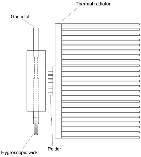
Figure 4. The embodiment of a heat exchanger using a Peltier[67].
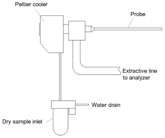
Figure 5. Schematic diagram of a sampling probe coupled with a Peltier cooler[70].
In the condensation method, water can be removed under solid or liquid phase. The advantage of the condensation method is its suitability for removing a high concentration of water from a high loading air volume. However, the condensate might affect the target gases. When the condensate is collected under the liquid phase, the absorption of soluble gases such as SOx, NOx, HCl, and NH3 can occur. It was reported that the loss of ozone was approximately 10% at 30% relative humidity and 40% at 80% relative humidity when the condensation method was applied to remove moisture for ozone measurement. Furthermore, SO2 was found to be lost at rates of 19.3%, 29.3%, and 61.5% at relative humidities of 30%, 50%, and 80%, respectively, when a cooler was used to remove the moisture[71]. Lee et al. (2019) investigated the effect of a cooler as a moisture pretreatment device in the analysis of methyl ethyl ketone (MEK), isobutyl alcohol (i-BuAl), methyl isobutyl ketone (MIBK), butyl acetate (BuAc), and styrene [72]. These are very highly water-soluble odorous compounds. It was reported that the losses of i-BuAL, MIBK, BuAc, and styrene were approximately 19%, 4%, 5%, and 10%, respectively, in association with 80% relative humidity. In addition, the reproducibility of their concentrations was approximately 8–31%. This indicated that the water liquid in the cooler kept absorbing and desorbing the analytes [72]. The U.S. EPA stated that HCl and NH3 are lost in the H2O condensate in a condenser[22][23]. Measurement bias of total hydrocarbon emitted from a hazardous waste incinerator was found when a refrigerant moisture removal device was used because VOCs and organic air pollutants might comprise highly, poorly, and non-water-soluble compounds[22]. On the other hand, if the condensate is removed under the solid phase, the absorption of soluble gases can be avoided. Several studies addressed a good recovery rate for highly water-soluble compounds when the moisture was removed under solid phase. It was found that the loss of SO2 at 150 ppmv was less than 2% when the moisture was removed at the solid phase (i.e., frost)[71]. Likewise, the losses of MEK, i-BuAl, MIBK, and BuAc at sub-ppbv level were 0%, 3.4%, 0.5%, and 2.1%, respectively [72]. Son et al. (2013) found that H2S (23 ppbv), CH3SH (16 ppbv), dimethyl sulfide (13 ppbv), and dimethyl disulfide (8 ppbv) had a recovery rate over 97% when the moisture in the sample was removed at the solid phase. Nevertheless, these studies were not conducted with respect to air pollutants in the ambient air with low moisture content rather than emission gases from a stack. Moreover, HCl or NH3 at the atmospheric conditions could still be absorbed on the ice surface due to the hydrogen bond[73][74]. Thus, more investigations should be implemented. In general, the advantages of the condensation method are the low cost, simple structure, and easy operation and maintenance. However, the loss of target analytes is a serious issue with the method. Moreover, the treatment of drain water is another drawback of the condensation method. Consequently, the condensation method is recommended to be used for the CEMS of poorly water-soluble compounds such as CO, CO2, NO, and CH4 when the moisture is removed under a liquid phase. On the other hand, if moisture is removed under a solid phase, higher water-soluble gases such as SO2 or NO2 could be applied. More comprehensive studies should be carried out to investigate the influence of the solid phase. A conversion process of highly water-soluble analytes to poorly water-soluble analytes would be an alternative when the moisture is removed under liquid phase. For example, the U.S. EPA suggested that a catalytic converter could be applied to convert the NH3 in the sample gas to NOx [23]. Then the sample gas could penetrate a condenser to remove moisture before moving into a NOx analyzer [23]. The summary of condensation methods with respect to different inventions is shown in Table 2. The condensation process, advantages, disadvantages, and recommendations of applicable analyte are listed.
Table 2. Development of condensation devices to remove moisture in the flue gas.
|
No. |
Method |
Condensation Type |
Advantages |
Disadvantages |
Recommendation of Applicable Analytes |
|
1 |
Refrigerated moisture removal device with improvement of heat exchanger [63] |
Heterogeneous |
- Reduced dimension of the device due to the absence of a water separator - High cooling efficiency - Less foiling - Allowable for high loading of moisture. |
- Complicated structure - Potential loss of highly water-soluble compounds |
- Poorly water-soluble gases such as CO, NO, CO2, and CH4 due to water droplets absorbing highly water-soluble compounds |
|
2 |
Refrigerated moisture removal device with an extra heat exchanger [64] |
Heterogeneous |
- High cooling efficiency - Allowable for high temperature of the inlet gas - Allowable for high loading of moisture. |
- Bulky device - Potential loss of highly water-soluble compounds |
- Poorly water-soluble gases such as CO, NO, CO2, and CH4 due to water droplets absorbing highly water-soluble compounds |
|
3 |
Two stages: refrigeration at ‒40 °C and desiccant bed[65] |
Heterogeneous |
-High cooling efficiency - Allowable for high loading of moisture - Suitable for highly water-soluble compounds. |
- Complex and bulky structure - Potential loss of certain compounds due to the adsorption of desiccants. |
- Highly water-soluble gases such as SO2 or NO2 under a solid phase |
|
4 |
Vortex tube [66] |
Homogeneous |
- Low energy consumption - Less maintenance required |
- Potential loss of highly water-soluble compounds |
- Poorly water-soluble gases such as CO, NO, CO2, and CH4 due to water droplets absorbing highly water-soluble compounds. |
|
5 |
Peltier moisture removal device [67] |
Heterogeneous |
- Compact size - Low energy consumption - Suitable for highly water-soluble compounds |
- Not operatable with a high loading amount of moisture - Unsuitable for a high temperature of the inlet gas |
- Highly water-soluble gases such as SO2 or NO2 under a solid phase. |
|
6 |
Two stages: Peltier and membrane [68] |
Heterogeneous |
- Allowable for high loading of moisture.
|
- Potential loss of certain compounds due to the selectivity of the membrane - Potential loss of highly water-soluble compounds due to water droplets. |
- Poorly water-soluble gases such as CO, NO, CO2, CH4 due to water droplets absorbing highly water-soluble compounds. |
|
7 |
Conical cooling tube using a Peltier [69] |
Heterogeneous |
- Compact size - Large contact surface - Easy manufacturing due to its simple structure. |
- Potential loss of highly water-soluble compounds due to water droplets. |
Poorly water-soluble gases such as CO, NO, CO2, and CH4 due to water droplets absorbing highly water-soluble compounds |
|
8 |
Peltier probe [70] |
Heterogeneous |
- Easy reduction in the temperature of an extractive line - Saving energy for a CEMS. |
- Hard to maintain due to in situ location - Potential loss of highly water-soluble compounds due to water droplets. |
Poorly water-soluble gases such as CO, NO, CO2, and CH4 due to water droplets absorbing highly water-soluble compounds. |
References
- Jahnke, J.A. Continuous Emission Monitoring; John Wiley & Sons, Inc.: Toronto, ON, Canada, 2000; pp. 404.
- Lillesand, T.; Kiefer, R.W.; Chipman, J.. Remote Sensing and Image Interpretation; John Wiley and Sons: Hoboken, NJ, USA, 2015; pp. 736.
- Trieu-Vuong Dinh; In-Young Choi; Youn-Suk Son; Jo-Chun Kim; A review on non-dispersive infrared gas sensors: Improvement of sensor detection limit and interference correction. Sensors and Actuators B: Chemical 2016, 231, 529-538, 10.1016/j.snb.2016.03.040.
- Youwen Sun; Wen-Qing Liu; Yi Zeng; Shi-Mei Wang; Shu-Hua Huang; Pinhua Xie; Xiao-Man Yu; Water Vapor Interference Correction in a Non Dispersive Infrared Multi-Gas Analyzer. Chinese Physics Letters 2011, 28, 073302, 10.1088/0256-307x/28/7/073302.
- Barouch Giechaskiel; M Matti Maricq; Leonidas Ntziachristos; Christos Dardiotis; Xiaoliang Wang; Harald Axmann; Alexander Bergmann; Wolfgang Schindler; Review of motor vehicle particulate emissions sampling and measurement: From smoke and filter mass to particle number. Journal of Aerosol Science 2014, 67, 48-86, 10.1016/j.jaerosci.2013.09.003.
- Simone Simões Amaral; João A. Carvalho Jr.; Maria Angélica Martins Costa; Cleverson Pinheiro; An Overview of Particulate Matter Measurement Instruments. Atmosphere 2015, 6, 1327-1345, 10.3390/atmos6091327.
- J. Leskinen; J. Tissari; O. Uski; A. Virén; T. Torvela; T. Kaivosoja; H. Lamberg; I. Nuutinen; T. Kettunen; J. Joutsensaari; et al.P.I. JalavaO. SippulaM.-R. HirvonenJ. Jokiniemi Fine particle emissions in three different combustion conditions of a wood chip-fired appliance – Particulate physico-chemical properties and induced cell death. Atmospheric Environment 2014, 86, 129-139, 10.1016/j.atmosenv.2013.12.012.
- Ruoting Jiang; Michelle L. Bell; A Comparison of Particulate Matter from Biomass-Burning Rural and Non-Biomass-Burning Urban Households in Northeastern China. Environmental Health Perspectives 2008, 116, 907-914, 10.1289/ehp.10622.
- Tiina Torvela; J. Tissari; Olli Sippula; T. Kaivosoja; Jani Leskinen; A. Virén; Anna Lahde; Jorma Jokiniemi; Effect of wood combustion conditions on the morphology of freshly emitted fine particles. Atmospheric Environment 2014, 87, 65-76, 10.1016/j.atmosenv.2014.01.028.
- Patricia Krecl; Johan Ström; Christer Johansson; Carbon content of atmospheric aerosols in a residential area during the wood combustion season in Sweden. Atmospheric Environment 2007, 41, 6974-6985, 10.1016/j.atmosenv.2007.06.025.
- Daniel Mellon; Simon J. King; Jin Kim; Jonathan P. Reid; Andrew J. Orr-Ewing; Measurements of Extinction by Aerosol Particles in the Near-Infrared Using Continuous Wave Cavity Ring-Down Spectroscopy. The Journal of Physical Chemistry A 2011, 115, 774-783, 10.1021/jp109894x.
- Anders Pettersson; Edward R. Lovejoy; Charles A. Brock; Steven S. Brown; A.R. Ravishankara; Measurement of aerosol optical extinction at with pulsed cavity ring down spectroscopy. Journal of Aerosol Science 2004, 35, 995-1011, 10.1016/j.jaerosci.2004.02.008.
- M. Elsasser; M. Crippa; Jurgen Orasche; Peter F Decarlo; Markus Oster; Mike Pitz; Josef Cyrys; T. L. Gustafson; J. B. C. Pettersson; Jurgen Schnellekreis; et al.A. S. H. PrévôtRobert A Zimmermann Organic molecular markers and signature from wood combustion particles in winter ambient aerosols: aerosol mass spectrometer (AMS) and high time-resolved GC-MS measurements in Augsburg, Germany. Atmospheric Chemistry and Physics 2012, 12, 6113-6128, 10.5194/acp-12-6113-2012.
- S. Hosseini; Q. Li; D. Cocker; D. Weise; A. Miller; M. Shrivastava; J. W. Miller; S. Mahalingam; M. Princevac; H. Jung; et al. Particle size distributions from laboratory-scale biomass fires using fast response instruments. Atmospheric Chemistry and Physics 2010, 10, 8065-8076, 10.5194/acp-10-8065-2010.
- Vincent, J.H. . Aerosol Sampling; John Wiley & Sons, Ltd.: Chichester, UK, 2007; pp. 636.
- Castellani, B.; Morini, E.; Filipponi, M.; Nicolini, A.; Palombo, M.; Cotana, F.; Rossi, F. Comparative Analysis of Monitoring Devices for Particulate Content in Exhaust Gases. Sustainability 2014, 6, 4287–4307, doi:10.3390/su6074287.
- Beatrice Castellani; Elena Morini; Mirko Filipponi; Andrea Nicolini; Massimo Palombo; Franco Cotana; Federico Rossi; Comparative Analysis of Monitoring Devices for Particulate Content in Exhaust Gases. Sustainability 2014, 6, 4287-4307, 10.3390/su6074287.
- D. A. Lundgren; D. W. Cooper; Effect of Humidify on Light-Scattering Methods of Measuring Particle Concentration. Journal of the Air Pollution Control Association 1969, 19, 243-247, 10.1080/00022470.1969.10466482.
- Paul Zieger; R. Fierz-Schmidhauser; Ernest Weingartner; U. Baltensperger; Effects of relative humidity on aerosol light scattering: results from different European sites. Atmospheric Chemistry and Physics 2013, 13, 10609-10631, 10.5194/acp-13-10609-2013.
- Rohan Jayaratne; Xiaoting Liu; Phong Thai; Matthew Dunbabin; Lidia Morawska; The influence of humidity on the performance of a low-cost air particle mass sensor and the effect of atmospheric fog. Atmospheric Measurement Techniques 2018, 11, 4883-4890, 10.5194/amt-11-4883-2018.
- Wenjia Shao; Hongjian Zhang; Hongliang Zhou; Fine Particle Sensor Based on Multi-Angle Light Scattering and Data Fusion. Sensors 2017, 17, 1033, 10.3390/s17051033.
- US EPA. EPA Handbook–Continuous Emission. Monitoring Systems for Non-Criteria Pollutants; United States Environmental Pro-tection Agency: Washington, DC, USA, 1997.
- US EPA. Ammonia CEMS Background; United States Environmental Protection Agency: Washington, DC, USA, 1993.
- Kong, S.; Shi, J.; Lu, B.; Qiu, W.; Zhang, B.; Peng, Y.; Zhang, B.; Bai, Z. Characterization of PAHs within PM10 fraction for ashes from coke production, iron smelt, heating station and power plant stacks in Liaoning Province, China. Atmos. Environ. 2011, 45, 3777–3785, doi:10.1016/j.atmosenv.2011.04.029.
- Yang, H.-H.; Lee, W.-J.; Chen, S.-J.; Lai, S.-O. PAH emission from various industrial stacks. J. Hazard. Mater. 1998, 60, 159–174, doi:10.1016/s0304-3894(98)00089-2.
- Shi, J.; Deng, H.; Bai, Z.-P.; Kong, S.; Wang, X.; Hao, J.; Han, X.; Ning, P. Emission and profile characteristic of volatile or-ganic compounds emitted from coke production, iron smelt, heating station and power plant in Liaoning Province, China. Sci. Total Environ. 2015, 515–516, 101–108, doi:10.1016/j.scitotenv.2015.02.034.
- Pawelec, A.; Chmielewski, A.; Licki, J.; Han, B.; Kim, J.; Kunnummal, N.; Fageeha, O.I. Pilot plant for electron beam treat-ment of flue gases from heavy fuel oil fired boiler. Fuel Process. Technol. 2016, 145, 123–129, doi:10.1016/j.fuproc.2016.02.002.
- Kim, J.-C.; Kim, K.-H.; Armendariz, A.; Al-Sheikhly, M. Electron Beam Irradiation for Mercury Oxidation and Mercury Emissions Control. J. Environ. Eng. 2010, 136, 554–559, doi:10.1061/(asce)ee.1943-7870.0000188.
- Malik, A.U.; Al-Muaili, F.; Al-Ayashi, M.; Meroufel, A. An investigation on the corrosion of flue gas sensor in boiler stack. Case Stud. Eng. Fail. Anal. 2013, 1, 200–208, doi:10.1016/j.csefa.2013.07.003.
- Anglada, J.M.; Martins-Costa, M.T.C.; Francisco, J.S.; Ruiz-López, M.F. Triplet state promoted reaction of SO2 with H2O by competition between proton coupled electron transfer (pcet) and hydrogen atom transfer (hat) processes. Phys. Chem. Chem. Phys. 2019, 21, 9779–9784, doi:10.1039/c9cp01105f.
- Li, K.; Yu, H.; Qi, G.; Feron, P.; Tade, M.; Yu, J.; Wang, S. Rate-based modelling of combined SO2 removal and NH3 recycling integrated with an aqueous NH3 -based CO2 capture process. Appl. Energy 2015, 148, 66–77, doi:10.1016/j.apenergy.2015.03.060.
- Seo, J.-B.; Jeon, S.-B.; Choi, W.-J.; Kim, J.-W.; Lee, G.-H.; Oh, K.-J. The absorption rate of CO2/SO2/NO2 into a blended aqueous AMP/ammonia solution. Korean J. Chem. Eng. 2010, 28, 170–177, doi:10.1007/s11814-010-0332-2.
- Zhao, Y.; Hao, R.; Wang, T.; Yang, C. Follow-up research for integrative process of pre-oxidation and post-absorption cleaning flue gas: Absorption of NO2, NO and SO2. Chem. Eng. J. 2015, 273, 55–65, doi:10.1016/j.cej.2015.03.053.
- Susianto; Pétrissans, M.; Pétrissans, A.; Zoulalian, A. Experimental study and modelling of mass transfer during simultane-ous absorption of SO2 and NO2 with chemical reaction. Chem. Eng. Process. Process. Intensif. 2005, 44, 1075–1081, doi:10.1016/j.cep.2005.03.001.
- Jahnke, J.A. Continuous Emission Monitoring, 2nd ed.; John Wiley & Sons, Inc.: Toronto, ON, Canada, 2000; ISBN 0-471-29227-3.
- Qu, M.; Abdelaziz, O.; Gao, Z.; Yin, H. Isothermal membrane-based air dehumidification: A comprehensive review. Renew. Sustain. Energy Rev. 2018, 82, 4060–4069, doi:10.1016/j.rser.2017.10.067.
- Cromer, C.J. Cooling system. US Patent US6237354B1, 2001. URL: https://patents.google.com/patent/US6237354B1/en (Ac-cessed on 30 Janunary 2020)
- Curtis, M. Air conditioning system with moisture control. US Patent US7191607B2, 2007. URL: https://patents.google.com/patent/US7191607B2/en (Accessed on 30 Janunary 2020)
- Endo, T.; Terada, H.; Katsumata, N.; Yagi, K.; Kawashima, K. Air conditioner and moisture removing device for use with the air conditioner. European Patent EP0816779A4, 1998. URL: https://patents.google.com/patent/EP0816779A4/en (Accessed on 30 Janunary 2020)..
- La, D.; Dai, Y.; Li, Y.; Wang, R.; Ge, T. Technical development of rotary desiccant dehumidification and air conditioning: A review. Renew. Sustain. Energy Rev. 2010, 14, 130–147, doi:10.1016/j.rser.2009.07.016.
- Mazzei, P.; Minichiello, F.; Palma, D. HVAC dehumidification systems for thermal comfort: A critical review. Appl. Therm. Eng. 2005, 25, 677–707, doi:10.1016/j.applthermaleng.2004.07.014.
- Mei, L.; Dai, Y. A technical review on use of liquid-desiccant dehumidification for air-conditioning application. Renew. Sus-tain. Energy Rev. 2008, 12, 662–689, doi:10.1016/j.rser.2006.10.006.
- Wu, G.; Cur, N.O. Squeezable moisture removal device. US Patent US20090158928A1, 2009. URL: https://patents.google.com/patent/US20090158928A1/en (Accessed on 30 Janunary 2020).
- Aine, H.E. Infrared optoacoustic gas analyzer having an improved gas inlet system. US Patent US4051372A, 1977. URL: https://patents.google.com/patent/US4051372A/en (Accessed on 30 Janunary 2020).
- Baccanti, M.; Magni, P. Process and apparatus for determining total nitrogen content by elemental analysis. European Patent EP0586969A2, 1994. URL: https://patents.google.com/patent/EP0586969A2/en (Accessed on 30 Janunary 2020).
- Jahn, M.D.; Griffin, M.T.; Popkie, N. Apparatus and method for water vapor removal in an ion mobility spectrometer. US Patent US7361206, 2008. URL: https://patents.google.com/patent/US7361206B1/en (Accessed on 30 Janunary 2020).
- Karbiwnyk, C.M.; Mills, C.S.; Helmig, D.; Birks, J.W. Minimization of water vapor interference in the analysis of non-methane volatile organic compounds by solid adsorbent sampling. J. Chromatogr. A 2002, 958, 219–229, doi:10.1016/s0021-9673(02)00307-2.
- Kolb, B.; Zwick, G.; Auer, M. A water trap for static cryo-headspace gas chromatography. J. High Resolut. Chromatogr. 1996, 19, 37–42, doi:10.1002/jhrc.1240190107.
- Legendre, M.G.; Fisher, G.S. Inlet system for direct gas chromatographic and combined gas chromatographic/mass spec-trometric analysis of food volatiles. US Patent US4245494A, 1981. URL: https://patents.google.com/patent/US4245494A/en (Accessed on 30 Janunary 2020)
- Namieśnik, J.; Wardencki, W. Water Vapour Removal from Gaseous Samples Used for Analytical Purposes. A Review. Int. J. Environ. Anal. Chem. 1999, 73, 269–280, doi:10.1080/03067319908032669.
- Son, Y.-S.; Lee, G.; Kim, J.-C.; Han, J.-S. Development of a Pretreatment System for the Analysis of Atmospheric Reduced Sulfur Compounds. Anal. Chem. 2013, 85, 10134–10141, doi:10.1021/ac401345e.
- Ahn, S.; Moon, J.; Kim, D.; Baek, S.; Ryoo, B. Clothes dryer with a dehumidifier. US Patent US20060117593A1, 2006. URL: https://patents.google.com/patent/US20060117593A1/en (Accessed on 30 Janunary 2020)
- Cromer, C.J. Heat pump dryer with desciccant enhanced moisture removal. US Patent US6094835A, 2000. URL: https://patents.google.com/patent/US6094835A/en (Accessed on 30 Janunary 2020)
- Lentz, L.E. Dehumidifier clothes dryer apparatus. US Patent US7458171B1, 2008. URL: https://patents.google.com/patent/US7458171B1/en (Accessed on 30 Janunary 2020)
- Naboulsi, Z.A. System to reduce moisture within a clothes dryer. US Patent US20150059201A1, 2015. URL: https://patents.google.com/patent/US20150059201A1/en (Accessed on 30 Janunary 2020)
- Sieben, F.; Volkel, T. Air dehumidifier for use in a dryer. US Patent US20120137535A1, 2012. URL: https://patents.google.com/patent/US20120137535A1/en (Accessed on 30 Janunary 2020)
- Araki, H.; Shibata, T.; Hatamiya, S.; Tsukamoto, M. Cooling apparatus, gas turbine system using cooling apparatus, heat pump system using cooling system, cooling method, and method for operating cooling apparatus. US Patent US8402735B2, 2013. URL: https://patents.google.com/patent/US8402735B2/en (Accessed on 30 Janunary 2020)
- Baudat, N.; Richardson, F. Direct turbine air chiller/scrubber system. US Patent US20010054354A1, 2001. URL: https://patents.google.com/patent/US20010054354A1/en (Accessed on 30 Janunary 2020)
- Kulkarni, A.M.; Ashley Mass, R.M.; Davies, J.C. Mist/moisture removal using fixed bed trickle columns. US Patent US8419844B1, 2013. URL: https://patents.google.com/patent/US8419844B1/en (Accessed on 30 Janunary 2020)
- Balinski, B.A.; Jackson, F.G.; McAllister, K.D. Controlled moisture removal in a laundry treating appliance. US Patent US10633776B2, 2020. URL: https://patents.google.com/patent/US10633776B2/en (Accessed in 30 May 2020)
- Kim, Y.-J. Washing machine having dehumidifying apparatus and dehumidifying method thereof. US Patent US20080295696A1, 2008. URL: https://patents.google.com/patent/US20080295696A1/en (Accessed on 30 Janunary 2020)
- Saukahanian, G.; Kruger, M. Dehumidifier for air utilized in laundry drying. US Patent US3866333A, 1975. URL: https://patents.google.com/patent/US3866333A/en (Accessed on 30 Janunary 2020)
- Downling, R.O. Compressed air dryer. US Patent US4235081A, 1980. URL: https://patents.google.com/patent/US4235081A/en (Accessed on 30 Janunary 2020)
- Nanaumi, K.; Baba, K. Heat exchanger for cooling system compressed air dehumidifiers. US Patent US4193443A, 1980. URL: https://patents.google.com/patent/US4193443A/en (Accessed on 30 Janunary 2020)
- Basseen, S.K.; Harlan, R.A. High efficiency air drying system. US Patent US4761968A, 1988. URL: https://patents.google.com/patent/US4761968A/en (Accessed on 30 Janunary 2020)
- Tosi, S. Gas analyzer with cooling apparatus. European Patent EP2124049A1, 2009. URL: https://patents.google.com/patent/EP2124049A1/en (Accessed on 30 Janunary 2020)
- Chapman, R.L.; Harman, J.N. Thermoelectric gas dryer. US Patent US4231256A, 1980. URL: https://patents.google.com/patent/US4231256A/en
- Groeger, H. Process and apparatus for pretreatment of a gas to be analysed. European Patent EP0291630A3, 1988. URL: https://patents.google.com/patent/EP0291630A3/en (Accessed on 30 Janunary 2020)
- Groeger, C.-M.; Groeger, H. Apparatus for separating vaporous compounds from a gas stream. European Patent EP0361068A3, 1989. URL: https://patents.google.com/patent/EP0361068A3/en (Accessed on 30 Janunary 2020)
- Bacharach, Inc., Technical note: Flue gas sample conditioning system (P/N 0024-7224), 2010. URL: http://www.mybacharach.com/wp-content/uploads/2015/08/Flue-Gas-Conditioner-Manual.pdf (Accessed in 11 November 2019)
- Kim, D.-J.; Dinh, T.-V.; Lee, J.-Y.; Choi, I.-Y.; Son, D.-J.; Kim, I.-Y.; Sunwoo, Y.; Kim, J.-C. Effects of Water Removal Devices on Ambient Inorganic Air Pollutant Measurements. Int. J. Environ. Res. Public Health 2019, 16, 3446, doi:10.3390/ijerph16183446.
- Lee, J.-Y.; Dinh, T.-V.; Kim, D.-J.; Choi, I.-Y.; Ahn, J.-W.; Park, S.-Y.; Jung, Y.-J.; Kim, J.-C. Comparison of Water Pretreatment Devices for the Measurement of Polar Odorous Compounds. Appl. Sci. 2019, 9, 4045, doi:10.3390/app9194045.
- Kondo, M.; Kawanowa, H.; Gotoh, Y.; Souda, R. Hydration of the HCl and NH3 molecules adsorbed on amorphous water–ice surface. Appl. Surf. Sci. 2004, 237, 510–514, doi:10.1016/j.apsusc.2004.06.063.
- Saukahanian, G.; Kruger, M. Dehumidifier for air utilized in laundry drying. US Patent US3866333A, 1975.


