Your browser does not fully support modern features. Please upgrade for a smoother experience.
Submitted Successfully!
 +1 credit
Thank you for your contribution! You can also upload a video entry or images related to this topic.
For video creation, please contact our Academic Video Service.
| Version | Summary | Created by | Modification | Content Size | Created at | Operation |
|---|---|---|---|---|---|---|
| 1 | Frank Simchen | + 4514 word(s) | 4514 | 2020-07-16 08:36:18 |
Video Upload Options
We provide professional Academic Video Service to translate complex research into visually appealing presentations. Would you like to try it?
Cite
If you have any further questions, please contact Encyclopedia Editorial Office.
Simchen, F.; Sieber, M.; Kopp, A.; Lampke, T. Plasma electrolytic oxidation. Encyclopedia. Available online: https://encyclopedia.pub/entry/1397 (accessed on 08 February 2026).
Simchen F, Sieber M, Kopp A, Lampke T. Plasma electrolytic oxidation. Encyclopedia. Available at: https://encyclopedia.pub/entry/1397. Accessed February 08, 2026.
Simchen, Frank, Maximilian Sieber, Alexander Kopp, Thomas Lampke. "Plasma electrolytic oxidation" Encyclopedia, https://encyclopedia.pub/entry/1397 (accessed February 08, 2026).
Simchen, F., Sieber, M., Kopp, A., & Lampke, T. (2020, July 21). Plasma electrolytic oxidation. In Encyclopedia. https://encyclopedia.pub/entry/1397
Simchen, Frank, et al. "Plasma electrolytic oxidation." Encyclopedia. Web. 21 July, 2020.
Copy Citation
Plasma electrolytic oxidation (PEO) is a promising method for the surface treatment of metals. The procedure takes place within passivating aqueous electrolytes under alternating current patterns and high process voltages. In so far suitable treatment parameters are chosen, this leads to the formation of protective ceramic coatings which technological properties can be adjusted within wide ranges.
The article gives an brief introduction to this topic, concerning a historical overview and a summary of the application fields as well as the layer forming mechanisms and parameter dependencies of this process.
plasma electrolytic oxidation
surface treatment
cermization
1. Definition
Plasma electrolytic oxidation (PEO), also called micro-arc oxidation (MAO), is an innovative method in producing oxide-ceramic coatings on metals, such as aluminum, titanium, magnesium, zirconium, etc. The process is characterized by discharges, which develop in a strong electric field, in a system consisting of the substrate, the oxide layer, a gas-steam envelope, and the electrolyte. The electric breakdown in this system establishes a plasma state, in which, under anodic polarization, the substrate material is locally converted to a compound consisting of the substrate material itself (including alloying elements) and oxygen in addition to the electrolyte components.
2. Historical Overview
Plasma electrolytic discharge phenomena were first described by Sluginov around 1880 [1]. In the 1920s, these were systematically examined by Güntherschulze and Betz as an aspect of the development of electrolytic capacitors [2]. In the early 1970s, Brown and co-workers derived a method from the phenomena described to produce ceramic conversion layers on Al substrates in alkaline electrolytes, which they referred to as Anodic Spark Deposition (ASD) [3]. In the 1980s and 1990s, the working groups of Kurze, Markov, Yerokhin and others made further progress, which led to the first practical applications [4,5,6].
Since then, the technological and commercial introduction of the PEO into practice by specialized companies has succeeded: Keronite (GB), Meotec, Innovent, AaST, Cermanod (DE), Hirtenberge (AT), Tekniker (ES) IBC (US), Manel (RU) MAO Environmental Production Technology (CN), the related specialist literature began to split up thematically. To respect the immense research activity in the field of PEO, current reviews are increasingly dealing with key topics such as special substrate materials [7,8,9], particle incorporation [10,11], selected technological properties [12,13] and characteristics of the discharge phenomena [14,15]. While excellent reviews from past decades [16,17] on the basics of the PEO exist, their coverage of current developments is limited.
3. Principles of Plasma Electrolytic Oxidation
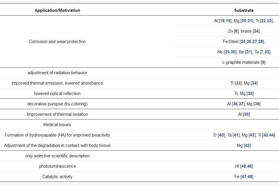
Plasma electrolytic oxidation (PEO) is also referred to as micro-arc oxidation (MAO), anodic spark deposition (ASD), plasma chemical oxidation (PCO), or anodic oxidation by spark discharge (ANOF, German: anodische Oxidation unter Funkenentladung). It is a conversion coating process for the surface refinement of several metallic materials, which tend to passivity in adequate aqueous electrolytes. In the first decade of the 21st century, PEO had also been developed for iron-based materials, which exhibit usually a poor passivation behavior. Table 1 shows a brief overview about literature known PEO processes, categorized according to application and substrate material.
Table 1. Selected applications and examples for the PEO of different materials.
The process is characterized by discharge, which develop under a strong electric field in a system consisting of the substrate, the oxide layer, a gas envelope, and the electrolyte, and it specifically determines the morphology, as well as the composition of the produced coatings. The electric breakdown in this system establishes a plasma state, in which, under anodic polarization, the substrate material is converted to a compound, comprised of the substrate material itself (including alloying elements), oxygen, and the electrolyte components.
The PEO process originates in the anodic oxidation of metals. When a metal electrode is polarized anodically in an electrolyte, different reactions are possible. A metal electrode, which is insoluble in the electrolyte, will lead to the evolution of oxygen (water electrolysis). If the metal electrode is soluble in the electrolyte, salts comprised of the electrode material and electrolyte components will occur, and the electrode will be consumed. The third possible reaction is the reaction of the anode material with the oxygen provided from the electrolyte to form a thin passive film, which itself is not or barely soluble in the electrolyte. Passive films are usually composed of oxides or hydroxides of the anode material, but more complex compounds of substrate and electrolyte components are also known to be formed. In order to prevent the reaction layer from flaking off, the unit cell volume of the reaction products must be in a favorable ratio to the volume of the unit cells of the substrate material. In case of metal oxides, this is characterized by the so-called Pilling-Bedworth ratio (PBR). For hydroxides and more complex compounds, the relationship is described as product/metal ratio PMR. [49,50].
It is crucial for a technologically-relevant passive film formation that it does not exhibit electron conductivity, but rather ion conductivity [2]. This behavior is strongly dependent on the combination of electrode metal and electrolyte. Figure 1 summarizes the possible current density-potential behavior of an anodically polarized electrode in an electrolyte.
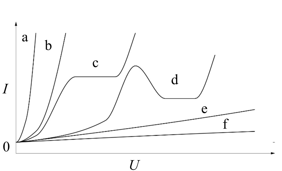
Figure 1. Principal types of the current density-potential behavior of an anodically polarized electrode in an electrolyte in accordance to Kurze [5]: a/b - dissolution, c - passivation in small potential range, d - complex behavior, e/f - passivation.
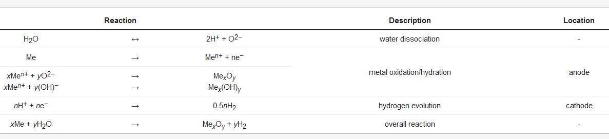
Only the passivating and, with some limitations, the complex behavior with a passive and a transpassive region are suitable for formation of reaction layers, which are appropriate for PEO initiation. A general overview over the chemical reactions that proceed during the growth of oxide e.g., hydroxide is given in Table 2.
Table 2. Generalized chemical reactions proceeding during oxide or hydroxide layer formation.
The formation of the ion-conductive oxide layer results in significant electric resistance. In a current-controlled, galvanostatic process, it is characterized by a steep increase in the cell voltage within the first few seconds. Increasing electric field strengths are necessary to realize a further current flow and further oxide growth.
The rise in the anodic potential over the electrolyte/oxide/electrode system leads to the partial formation of a gas film around the electrode. This film consists of oxygen, arising from the electrochemical, or in later process states with high local energy input, thermal decomposition or vaporization of water. Additionally, the formed film further increases the electric resistance in the system electrolyte/gas/oxide/electrode. Thus, perpetuation of the current flow requires an increase of the potential until the strength of the electric field in the aforementioned system reaches a critical value, and the breakdown occurs. All this typically happens within the first minute of the process [17].
The breakdown of the system is mainly affected by the substrate material and the electrolyte composition, while it is independent of the current density, temperature, surface roughness, electrolyte movement, and the history of the system [51,52].
By injection of electrons at the electrolyte/gas interface, which acts as a quasi-cathode (equipotential area of the electric field), a discharge channel evolves and penetrates the oxide layer. Within the discharge channel, thermally-activated ions originating from the substrate metal are ejected and move away from the substrate, due to the migration in the electric field, while oxygen ions move towards the substrate. The oxide is then formed in a reaction of the substrate ions and oxygen ions and is deposited in the boundary regions of the channel. The discharge channel is characterized by a local current flow of an order of magnitude several kiloamperes per square centimeter under a high electric field, which results in enormous energy density. Thus, temperatures of several thousand Kelvin may occur locally. At the beginning of the discharge event, the breakdowns are concentrated on those surface regions with the highest electric field strength. Small, discrete micro-discharges are visible. In a galvanostatic process, the steep rise of the cell voltage gives way to a substantially less-pronounced increase or even slight decrease of the voltage. During the evolution of the process, the discharges become larger, while fewer discrete breakdown events are visible. Therefore, the energy within the discharges increases. This leads to a series of consequences: (1) The formation of high-temperature crystalline phases is promoted (e.g., α-alumina). This does not only imply the direct formation of these phases, but also the phase transformation of already-formed oxide in later process stages. (2) The direct vicinity of the discharge channel is heated. Since the breakdown voltage of the electrolyte/gas/oxide/electrode system decreases with increasing temperature, the initiation of a new discharge in the vicinity of a former discharge is promoted. However, no negative effect on the electrode metal occurs, since the thermal influences of the discharge events are limited to small volumes. The substrate usually does not suffer significant heating. (3) Re-melting of the oxide occurs. Since the dissipation of heat towards the electrolyte is generally higher than that towards the substrate, near-substrate regions of the coatings can be rather loose morphology in this region. (4) Large discharges can destroy the formed oxide coating. The occurrence of such detrimental discharges is dependent on the process parameters. It can take place several minutes to hours after the initiation of the first discharges and should be avoided. In a galvanostatic process, the cell voltage generally continues to increase at a relatively low rate, but it usually drops instantaneously with the occurrence of large and deteriorating discharge. The time on which this stage of the process is reached is strongly dependent on the process parameters. It is advisable to choose process time and parameters so that this critical stage is avoided [53,54].
An example of the discharges evolution on a sample of the magnesium alloy AZ31 during the PEO in an alkaline silicate electrolyte is given in Figure 2. The brighter regions reflect the discharge action with brightness as a measure for the discharge intensity. The characteristic growth of discharges and the decrease of their number are observable in Figure 2 as well.
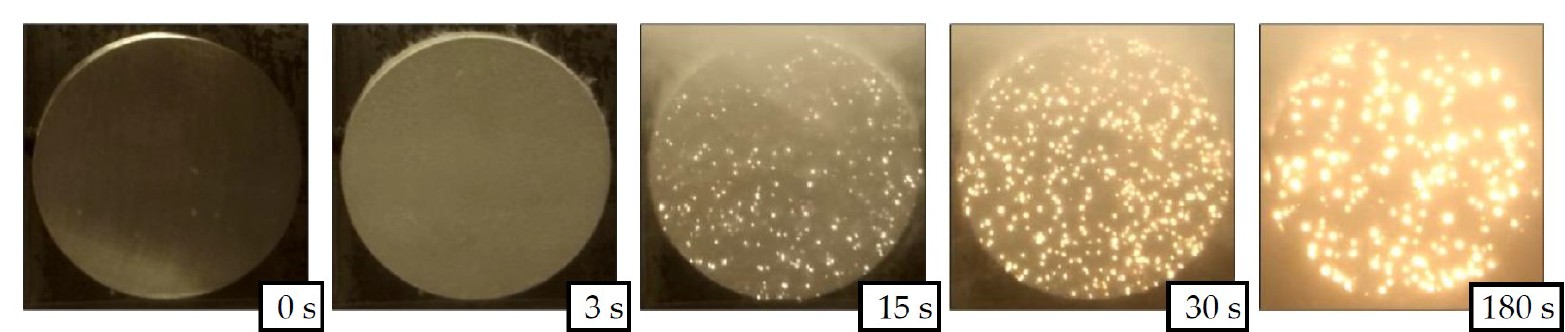
Figure 2. Evolution of discharge distribution and intensity in relation to the process time for the PEO of an AZ31 magnesium alloy in an alkaline silicate electrolyte. Brightness correlates with discharge intensity on the respective surface region of the sample.
The three-layered structure of PEO coatings which typically occurs is shown schematically in Figure 10. The oxide coating is comprised of a nanometer-thin and, according to the described model, nearly defect-free (amorphous) barrier layer at the oxide/substrate interface [55,56], a rather compact working layer, and a loose outer layer, the so-called technological layer [18,19]. The thickness of the compact and the technological layer can stretch from a few microns to several hundred microns, depending on the conditions under which the PEO process is performed. Hence, the entire process is controlled by the electrical field and takes place under high electric potentials, and the PEO shows a very good throwing power which results in a homogenous layer thickness distribution, even on working pieces with complex geometry.
In the following, the different dependencies of the PEO process, primarily the substrate composition, the electrolyte used, the applied electrical regime, as well as their interaction with each other are discussed. Based on this, the formation and the technological properties of the resulting PEO layers are discussed and selected current application options are presented. Figure 3 summarizes the order of the focal points in this review using a schematic representation of the process steps during the plasma electrolytic oxidation.
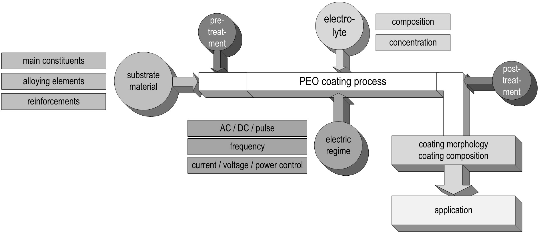
Figure 3. Schematic graphic representation of the PEO process and its dependencies from the uncoated substrate over the process parameters to the application.
4. Process Parameters and Coating Properties
4.1. Substrate
Plasma electrolytic oxidation in common low concentration aqueous electrolytes is at its core a conversion coating process. Hence, the nature of the oxide strongly depends on the substrate composition. The metal ions participating in the electrochemical reactions during the PEO process (Table 1) are determined by the treated material. Generally, oxides of the substrate metal are the main constituents of the coatings. The substrate conversion naturally includes alloying elements and precipitates in the metal as well as reinforcement phases in case of metal matrix composites. For aluminum, this is shown in Figure 4 and Figure 5. Figure 4 shows a scanning electron microscopy (SEM) picture of the oxide/substrate interface in the cross section of an oxide coating, produced by PEO in an alkaline silicate electrolyte on thermally-sprayed aluminum comprised of copper particles in BSE-mode (element contrast).
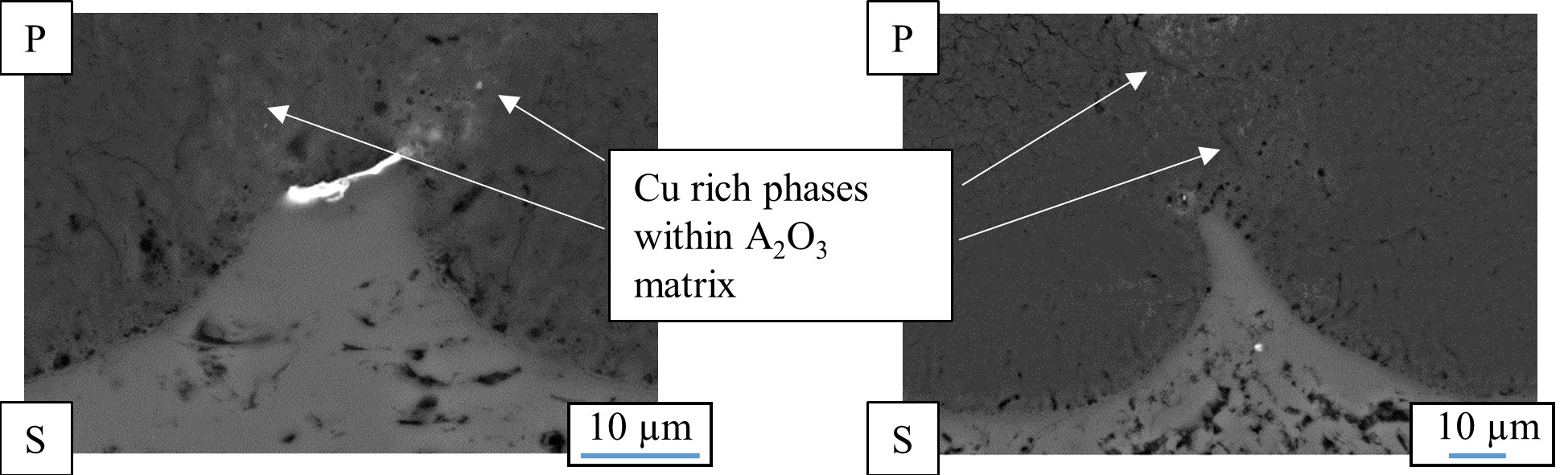
Figure 4. Cross section of the oxide/substrate interface of a PEO coating produced on thermally sprayed aluminum comprised of copper particles (P – PEO layer, S – Substrate). The brighter regions reflect a higher atomic number of the displayed material (SEM in BSE-mode – element contrast).
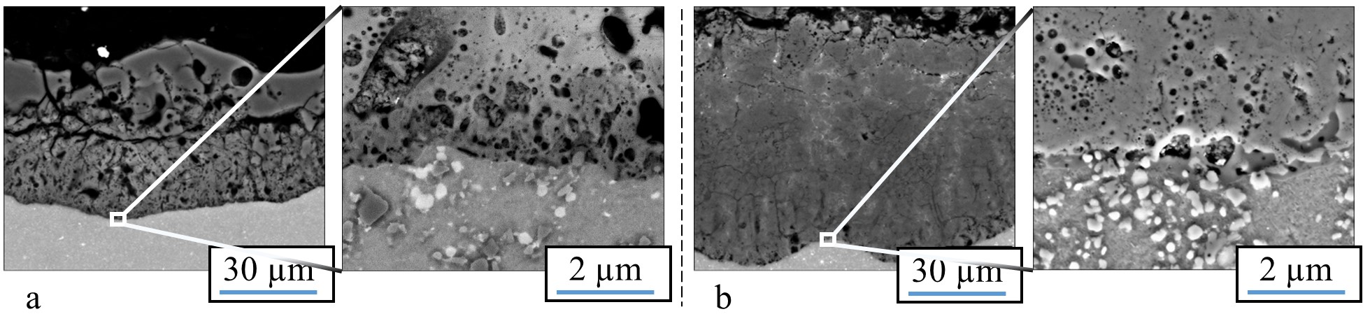
Figure 5. Cross section of the oxide produced in a PEO process on a SiC- (a) and a Al2O3 - (b) particle- reinforced aluminum alloy of the 2000 series [57]. (Reprinted from [57]. Copyright from 2016 IOP).
The bright fraction in the image represents a copper particle in the substrate. In the oxide above, the copper is obviously incorporated. It is also noticeable that the copper particle obstructs the conversion of the substrate, as in the surroundings, more of the substrate material has been consumed by the conversion coating process. Figure 5 shows a cross section of an oxide coating produced on an aluminum matrix composite (AMC) reinforced with silicon carbide or aluminum oxide particles.
It is obvious that the presence of SiC in the aluminum matrix leads to an increased number of flaws in the oxide, which are correlated to gas evolution at the electrically conductive particles. Remains of the particles, which are also partly converted, can be found in the pores of the coatings. However, under the high over-potential, the conversion of the silicon carbide particles takes place, presumably under gas evolution. This also results in a lower coating thickness, since the current efficiency is deteriorated by the evolution of gas. Unlike the presence of SiC, the presence of electrically non-conductive Al2O3 particles within the substrate does not affect the morphology or mechanical properties of the resulting PEO layer [57].
For aluminum in general, the existence of alloying elements like zinc, copper, or magnesium is likely to impede the transition from the metastable γ-phase to the high-temperature α-phase [58,59]. In addition, the alloying elements significantly influence the oxide phase distribution within the PEO layer [18]. Meanwhile, for magnesium alloys, the achievable coating thickness grows with an increasing content of aluminum or rare earths [55].
However, the coating composition and morphology are, not only influenced by the substrate material, but can also be altered by the incorporation of electrolyte constituents, as will be shown in the following section.
4.2. Electrolyte
Section 3 includes a classification of electrolyte components with regard to their passivating or dissolving behavior towards the substrate. Nevertheless, other classifications are possible. With regard to the incorporation of foreign compounds into the oxide coating, electrolytes are classified as follows: (1) electrolytes leading only to oxygen incorporation, (2) electrolytes leading to the incorporation of foreign compounds by anions, (3) electrolytes leading to the incorporation of foreign compounds by cations, and (4) electrolytes containing macroscopic particles, which are incorporated into the oxide by cataphoretic processes [17].
Common salts for the PEO of aluminum, magnesium, titanium, and their alloys in alkaline media are, amongst others, silicates, phosphates, aluminates, fluorides, borates, and stannates. Especially for the PEO of magnesium and its alloys, acidic or pH-neutral electrolyte compositions are used instead of alkaline electrolytes, e.g., fluoric acid, phosphoric acid, and/or boric acid in combination with organic additives, c.f. [60,61]. By incorporating elements provided by the electrolyte, the composition of the oxide can be altered substantially.
Some examples are shown in Figure 6, which contains x-ray diffractograms of uncoated Mg-AZ31 (a) as well as samples of the same material, which were treated by PEO within different alkaline media (b–d). The use of a low concentration phosphate electrolyte leads to the formation of a magnesia layer by substrate conversion. On the other side, highly concentrated solutions allow for the incorporation of electrolyte constituents into the resulting layer. In this way, PEO layers are formed in aluminate-rich solutions, which contain high proportions of crystalline MgAl2O4 spinels (6c) [21]. By using silicate-rich electrolytes, it is even possible to completely replace MgO in the PEO layer and to produce coatings, consisting of amorphous Mg / Si mixed oxides (6d), e.g., [20]. Since aluminum- or silicon-containing mixed oxides are usually superior over magnesia or titania in regards to their hardness and chemical resistivity, this approach is relevant for the PEO of magnesium and titanium alloys. Therefore, the method is converted from a conversion process to a mixed form of conversion and deposition. Another prominent example of the incorporation of electrolyte constituents into the oxide coatings is the formation of hydroxyapatite-containing PEO coatings on titanium from calcium- and phosphorus-containing electrolytes, c.f. [43,44]. Additionally, the coloring of working pieces by PEO for decorative or optical applications (e.g., blackened by use of vanadate ions) is already in practical use, c.f. [34,36].
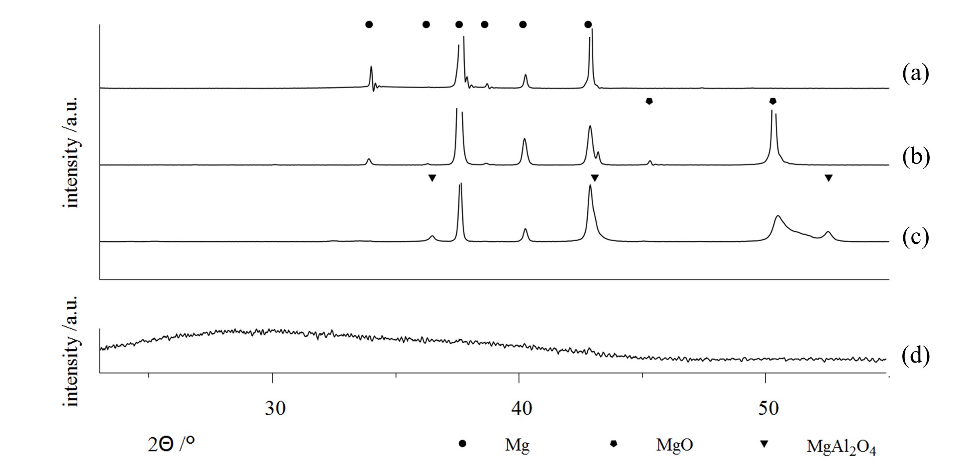
Figure 6. X-ray Diffraction (XRD)-diffractograms on bare AZ31 substrate, (a) and PEO coatings on AZ31 generated within several alkaline electrolytes; a low concentration phosphate solution, designed for substrate conversion, (b) high concentration silicate and aluminate electrolytes, designed for focused incorporation of electrolyte constituents (c,d) [20,21] (Apapted from [20,21]).
For the PEO of aluminum, the widely-used silicate components lead to the incorporation of large amounts of silicon oxides or alumina-silica-mixed-phases (e.g., mullite), have a passivating effect on the aluminum substrate, while also not dissolving the formed alumina. This generally increases the achievable coating thickness and results in a compact morphology of the coatings. In contrast, the dissolution of alumina in strongly alkaline solutions [62,63] allow for an adjustment of the coating growth through the addition of hydroxide to the electrolyte [4]. However, recent investigations indicate that this mechanism mainly affects the amorphous alumina phases, c.f. [18].
4.3. Electric Regime
The electric regime during PEO can be determined by the control parameter (current density or cell voltage), the type of the supplied parameter (direct, alternating, pulse current/voltage), and the definition of the regime (frequency, breaks, limits etc.). Under direct current or voltage, the discharge events become ever more intense during the progression of the process. This includes large discharges with long life periods, which can have a deteriorating effect on both, the formed oxide and the substrate and thus lead to irreparable defects. This behavior results from excessive energy transfer and heat release. Therefore, pulse or alternating current or voltage regimes are used to limit the effect of the strong discharges and to facilitate the formation of thick oxide coatings up to a few hundred microns. Thus, the PEO process can be prolonged, the number of defects in the coatings decreased, and the formation of a thick technological layer on top of the coating is impeded. In the following, the effects of a pulsed regime and of an alternating regime shall be discussed.
In a pulse regime, the control parameter (current or voltage) is regularly set to a low value, typically to zero. During the formation of the barrier layer at the beginning of the process (the pre-spark stage), this only affects the process substantially, if the substrate material or the oxide are dissolved by the electrolyte.
The break in current flow regime gives time for chemical dissolution and can lead to a slower growth of the barrier oxide. In most cases, the barrier layer growth accelerates, since the break allows for the compensation of potential concentration gradients. Furthermore, the repeated steep rise of the control parameter results in a significant mass/charge transfer towards the substrate. After formation of the barrier layer, the system behaves like a capacitor. This includes that current flow occurs only above of a certain potential threshold. At each rising edge of the pulse, collision ionization is likely to occur and implies that the initiation of short, but intense discharge events are favored, as opposed to those favored in a direct current or voltage regime. At the falling edge of the pulse, the current flow is interrupted, and thus the length of the discharge periods are limited. Using this strategy, the PEO process can be performed for a longer duration without the development of large and deteriorating discharges. The utilization of an alternating regime likewise limits the life period of discharges. In addition, the cathodic half period of an alternating regime can lead to a partial electrochemical reduction of the oxide. Thus, the formation of a barrier layer sufficient for discharge initiation at the beginning of the PEO process will be prolonged. During the PEO process, discharge can also occur in the cathodic branch of the electric regime. This discharge is usually less intense than the discharge in the anodic branch. A lower amount of energy is introduced into the coating. However, the cathodic discharge is also prone to heat up the oxide locally, and are thus, likely to result in a reduction of the field strength necessary for the breakdown in the following anodic branch [54].
In general, the interactions of the substrate/electrolyte-combination with the electrical regime are complex and still a subject of research. A promising approach to gain experimental access to the relationships is the analysis of the electrical process data. Since, in contrast to other electrolytic surface treatment methods, PEO results in the formation of high-ohmic layers, these affect, above all in the case of current-controlled regimes, to what extent the pre-defined electrical pulse is mapped correctly in the experimental setup. Figure 7 shows a schematic representation of these relationships. Figure 8 illustrates them using the example of PEO of Mg-AZ31 samples with identical experimental parameters using different electrolytes.
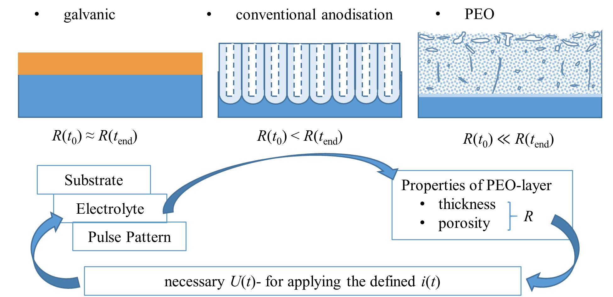
Figure 7. Schematic representation (not to scale) of obtained-layer morphology and development of layer resistance R for different electrolytic coating methods relation to the process time t, interactions of the process variables voltage U(t) and current i(t) pattern with the layer characteristics during the PEO.
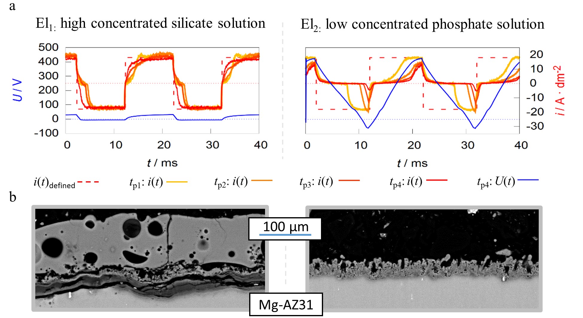
Figure 8. Pulse shape development of current-controlled PEO experiments for different process times (tp1–4 = 1, 5, 10 and 20 min) under identical experimental conditions in two different alkaline electrolytes El1/2 (a) SEM-micrographs of the resulting layers after 22:30 min of treatment time (b).
The working media used are designed for focused incorporation of electrolyte constituents into the coating (El1) and PEO layer formation by substrate conversion (El2). The current time characteristics measured during the process within the high concentration silicate solution show that the predefined symmetric rectangular current pattern is transmitted largely correctly to the system under investigation. Furthermore, the remaining deviations between predefined and measured pulses are decreasing with progression of the process time. In contrast to the effects described above, the experiment within the low concentration phosphate electrolyte shows a significant delay in the current flow after polarity reversal in both, the cathodic and anodic partial period. The delays even increase during the process. Additionally, the experiments in electrolyte 2 result in much higher voltages over the entire treatment time. This is exemplified by the voltage pattern after 20 min and leads to a higher consumption of electrical energy.
Therefore, one might assume that the experiment in electrolyte 1 had the more desirable process characteristics. However, consideration of the micrographs displayed in Figure 8b show that, despite a significantly increased layer thickness, an insufficient layer adhesion was achieved within electrolyte 1. Conversely, the coating formed in electrolyte 2 shows a good substrate bonding. Thus, the more pronounced delay of the current flow with increasing process time is not an error in the control of the behavior of the rectifier but belongs to the PEO process characteristics. A good adhesive layer of ceramic leads to an increasing electrical resistance at the substrate/electrolyte interface, which indicates that the current flow only starts after the rectifier has readjusted to higher process voltages. If the layers produced adhere poorly or worse with increasing treatment time, this mechanism is suppressed.
This behavior is mentioned at this point in discussion because, in addition to the layer state, the ignition voltage for discharge initiation during the PEO is also influenced by the electrolyte composition. However, the electrolyte resistance (or electrolyte conductivity) is negligible in most cases [51]. The depiction of the electrical process variables in relation to each other allows further conclusions to be drawn about the underlying process characteristics. Figure 9 represents the process data shown in Figure 8 as voltage current curves (VCC), as well as the course of specific voltage values over the treatment time.
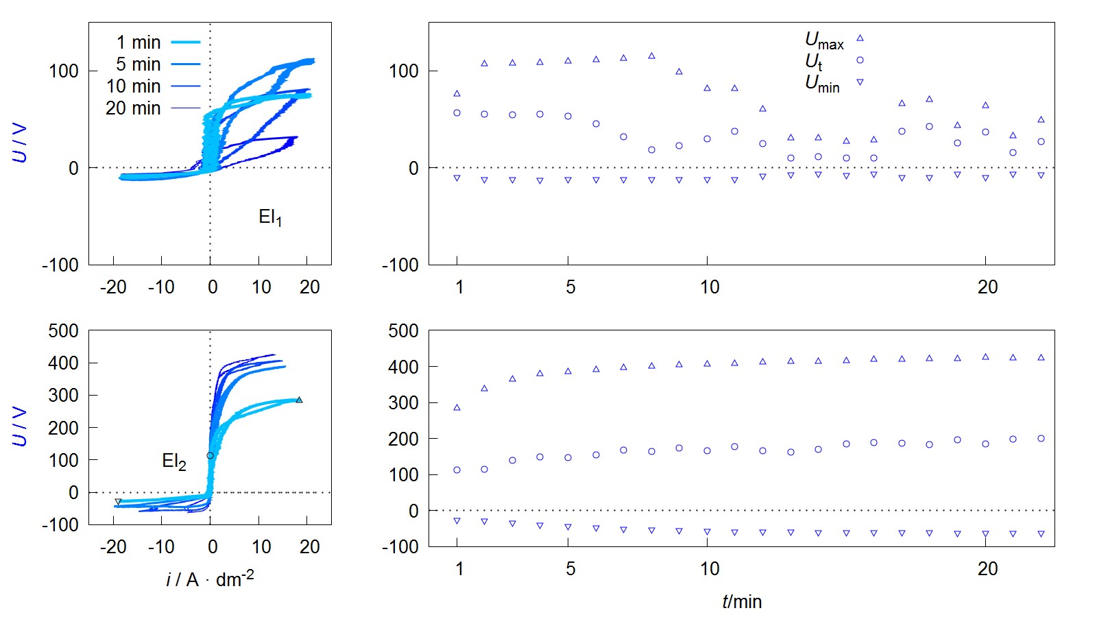
Figure 9. Voltage current curves of VCC (left) and course of maximum Umax, threshold Ut and minimum Umin voltage during the process (right) of the PEO experiments described in Figure 8.
Depending on the form of the representation, these curves are also referred to as current-voltage curves or characteristics or more generally as oscillograms. The value of the maximum Umax and minimum Umin voltage during one pulse cycle can be easily extracted from such a diagram. Furthermore it is possible to see that the downward branch of the anodic period shows a characteristic point at which the current flow stops while the voltage is still above the coordinate origin. This behavior can be observed at the process data of PEO on aluminum under various conditions, shown in several publications [64,65,66,67,68]. Within studies by Suminow et al. the value is called threshold voltage [1,2]. Duan et al. describes the polarization level below, when the charge carrier flow comes to a standstill as a critical conductive voltage [69]. Both research groups investigate the course of this voltage in dependence of the treatment time and assume that the value is proportional to the electrical isolation properties of the PEO layer after collapse of the plasma electrolytic discharges. Therefore, an increasing Ut indicates layer thickness growth and/or a decrease in the defect density within the layer. Insofar that this is correct, the evaluation of Ut allows, with respect to the anti-corrosive properties of the resulting PEO layers, the determination of optimal treatment times. In addition, the workload for materialographic examinations are reduced, since Ut provides automatically accessible information about the layer morphology. In contrast to microstructure images, these relate not only to a selected two-dimensional area but to the PEO layer along the entire substrate geometry. Hence, the method would be interesting also for non-destructive quality control.
Another interesting peculiarity of the VCCs shown in Figure 9 is that the ascending and descending anodic branches are not congruent. This is in accordance with recent studies by Ragov et al., which deal in detail with the analysis of electrical process data of the PEO of aluminum. Accordingly, the so-called hysteresis effects only occur in pulse regimes with cathodic components. The different conductivities in the rising and falling region of the anodic partial pulse are attributed to cathode-induced changes (CIC). These among others are substantiated by the incorporation of cations in a thin reaction layer at the substrate layer/interface of the so-called active zone. The subsequent release of the cations at the beginning of the anodic pulse leads to a brief increase in the electrical conductivity of the system. It is assumed that the few nm thick active zone has a strongly disproportionate contribution to the total electrical resistance of the layer system [70,71,72].
This would limit the significance of the threshold voltage mentioned above. Provided that the results can be transferred to the PEO of magnesium, the more pronounced hysteresis effects in Figure 9 for electrolyte 1 can be explained by the fact that there are significantly more cations in the electrolyte and the cathodic partial pulses are mapped almost completely.
Information
Subjects:
Materials Science, Coatings & Films
Contributors
MDPI registered users' name will be linked to their SciProfiles pages. To register with us, please refer to https://encyclopedia.pub/register
:
View Times:
4.3K
Revision:
1 time
(View History)
Update Date:
21 Jul 2020
Table of Contents


Notice
You are not a member of the advisory board for this topic. If you want to update advisory board member profile, please contact office@encyclopedia.pub.
OK
Confirm
Only members of the Encyclopedia advisory board for this topic are allowed to note entries. Would you like to become an advisory board member of the Encyclopedia?
Yes
No
${ textCharacter }/${ maxCharacter }
Submit
Cancel
Back
Comments
${ item }
|
${ item.createdUser.fullName }
${ item.createdAt }
${ item.vote }
${ item.reply }
Delete
${ reply.createdUser.fullName }
${ reply.createdAt }
${ reply.vote }
Delete
There is no reply to this comment~
${ item.replyTextCharacter }/${ item.replyMaxCharacter }
Submit
Cancel
More
No more~
There is no comment~
${ textCharacter }/${ maxCharacter }
Submit
Cancel
${ selectedItem.replyTextCharacter }/${ selectedItem.replyMaxCharacter }
Submit
Cancel
Confirm
Are you sure to Delete?
Yes
No