Submitted Successfully!
To reward your contribution, here is a gift for you: A free trial for our video production service.
Thank you for your contribution! You can also upload a video entry or images related to this topic.
Version Summary Created by Modification Content Size Created at Operation
1 + 2795 word(s) 2795 2021-07-05 04:30:41

Video Upload Options

Do you have a full video?

Confirm

Are you sure to Delete?
Cite
If you have any further questions, please contact Encyclopedia Editorial Office.
Wang, Y. Blood-Plasma Self-Separation in Self-Driven Microfluidics. Encyclopedia. Available online: https://encyclopedia.pub/entry/11905 (accessed on 23 April 2024).
Wang Y. Blood-Plasma Self-Separation in Self-Driven Microfluidics. Encyclopedia. Available at: https://encyclopedia.pub/entry/11905. Accessed April 23, 2024.
Wang, Yudong. "Blood-Plasma Self-Separation in Self-Driven Microfluidics" Encyclopedia, https://encyclopedia.pub/entry/11905 (accessed April 23, 2024).
Wang, Y. (2021, July 10). Blood-Plasma Self-Separation in Self-Driven Microfluidics. In Encyclopedia. https://encyclopedia.pub/entry/11905
Wang, Yudong. "Blood-Plasma Self-Separation in Self-Driven Microfluidics." Encyclopedia. Web. 10 July, 2021.
Blood-Plasma Self-Separation in Self-Driven Microfluidics
Edit

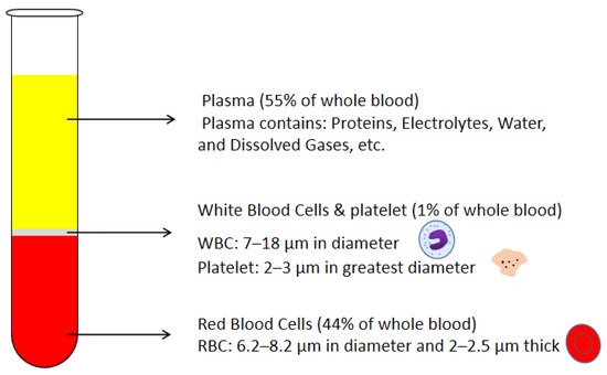
Blood plasma is the most commonly used biofluid in disease diagnostic and biomedical analysis due to it contains various biomarkers. The majority of the blood plasma separation is still handled with centrifugation, which is off-chip and time-consuming. Therefore, in the Lab-on-a-chip (LOC) field, an effective microfluidic blood plasma separation platform attracts researchers’ attention globally. Blood plasma self-separation technologies are usually divided into two categories: active self-separation and passive self-separation. Passive self-separation technologies, in contrast with active self-separation, only rely on microchannel geometry, microfluidic phenomena and hydrodynamic forces. Passive self-separation devices are driven by the capillary flow, which is generated due to the characteristics of the surface of the channel and its interaction with the fluid. Comparing to the active plasma separation techniques, passive plasma separation methods are more considered in the microfluidic platform, owing to their ease of fabrication, portable, user-friendly features.

passive self-separation microfluidics microfiltration sedimentation Dean vortex hydrophilicity

1. Introduction

Many recent advancements are developed in the Lab-on-a-chip field. However, the promotion of point-of-care (POC) technology is still an issue. POC devices take advantage of LOC technology and have a more comfortable, cheap, lab-free, and convenient diagnosis process instead of the traditional laboratory process [1][2][3][4][5][6][7]. In the development of LOC technology, sample preparation is always an obstacle, especially in microfluidic platforms [8][9][10][11][12][13][14][15][16][17]. Blood is the most commonly used biofluid sample in LOC devices. There are many commercial applications that existed; lateral flow immunoassay applications; sandwich assays and competitive assays, vertical flow immunoassay application; antibody conjugation and screening, and paper microfluidic implementation; glucose detection, 3D devices for glucose detection, and environmental and food safety tests [18][19][20][21][22][23]. Human whole blood comprises all blood components: red blood cells (RBCs), white blood cells (WBCs), platelet, and plasma. Healthy human blood is around 55% plasma and 45% RBCs [8]. The sizes of each blood component are shown in Figure 1 [24][25][26]. When the blood sample is the analyte of LOC devices, which component of blood is desired should be considered. In many LOC applications, plasma is the desired analyte that contains the target biomarkers to be detected. For example, in ovarian cancer detection, CA-125 and HE-4 antigens are usually suspended in the plasma and are used as biomarkers in ovarian cancer diagnostics [27][28][29][30][31][32][33][34][35][36]. Furthermore, the viscosity of the blood sample affects the design of the microfluidic devices. The viscosity of blood varied with the patients’ sex, health conditions, and diet. The viscosity of the whole blood mainly depends on the hematocrit. The higher the hematocrit of the whole blood, the more viscous the whole blood is. Temperature is another factor that affects the viscosity of the blood. There should be a temperature difference between the blood in the microchannel and blood in vivo. Additionally, the viscosity of the whole blood affects the flow rate of blood samples in the microfluidic channel. Therefore, the viscosity variation of different patients should also be considered in the microfluidic device design. The separation of plasma is the first step in most biomedical analysis assays. The standard separation process is centrifugation, as it is time-consuming and off-chip. It is not an ideal technique for microfluidic LOC devices [37]. Therefore, an effective and capillary-scale volume delivery system is expected to separate blood plasma and be integrated into the microfluidic sensing platform. Various separation technologies such as size-based particle sorting [38][39], active self-separation with external devices were concluded and discussed in many papers [40][41][42]. This paper is mainly focusing on the passive blood-plasma self-separation during capillary-driven flow in a microfluidic platform, Figure 2 shows the passive self-separation techniques discussed in this paper. In contrast with active self-separation techniques, passive blood-plasma self-separation does not need external forces or functionalities but is only driven by capillary flow enabled by a microchannel with hydrophilic walls [43][44][45][46][47][48][49][50]. Even though much research is carried out on developing passive blood-plasma self-separation systems in recent years, capillary-scale plasma preparation is still the bottleneck to the LOC technology.
Figure 1. Schematic drawing of blood components and corresponding volumetric percentages in the whole blood.
Figure 2. Schematic representation of the passive self-separation techniques discussed in this review paper.
Various challenges are considered when developing a passive blood-plasma self-separation system. First of all, volume is limited in LOC devices. To ensure the comfort of patients, 1–2 μL of blood is the suggested volume of a finger prick [51]. With this small-scale blood sample, microchannel size is also limited. Due to this limitation, many hydrodynamic methods cannot have full effects on the plasma separation, such as the Dean vortex effect is limited by the low flow rate and low Reynolds number of the blood flow. A short separation time is also expected in the blood delivery systems. Usually, plasma is ideally separated and collected from whole blood in few minutes in the POC applications. With the long-time separation process, the whole blood has an increased risk of coagulation [52]. Clogging is another challenge, especially in the microfluidic channel with micro-filtration [53]. With continuous blood flow passing through the micro-filtration, blood cells accumulate in the filters and gradually block the micro-structures and stop the self-separation process. The throughput and purity of separated plasma are also included in the consideration [54]. Lastly, the integration of the blood delivery system and the sensing platform is a challenging problem. Numerous studies have been performed on sample preparation and integration and have been discussed for many years [55][56]. The integration process itself has its own difficulties, such as leakage problems, the complexity of disparate materials, etc.
The fabrication processes of the microfluidic devices are mostly included in nanofabrication and have been mentioned by many papers. However, to have a capillary-driven flow in the microchannels, surface treatments are needed when the channel materials are naturally hydrophobic. There are many methods to change the hydrophilicity of the material surface. 1. Oxygen plasma treatment. The reactive species generated by oxygen plasma attacks the siloxane backbone of PDMS to form an oxygen-rich SiOx silica-like layer and Si-OH surface structures [3]. 2. Nanoparticle deposition. There are many ways to deposit nanoparticles onto the material surface: Deposition by Electro-spinning, Spontaneous Growth on Surfaces, Deposition by Spray Coating, etc. For example, this paper mentioned that Lee et al. sprayed a layer-by-layer (LbL) nano-assembly layer on the top surface [57]. 3. Chemical etching. Immersion into the particular chemical can form a nanostructured layer on the material surface, changing the surface’s wettability [58].

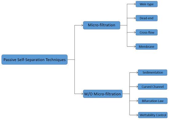
2. Passive Self-Separation with Filtration Using Micro-Structures

The blood plasma microfiltrations are usually categorized into four design types:1. Weir-type filtration 2. Dead-end pillar filtration 3. Cross-flow filtration, and 4. Membrane filtration [59]. A weir filter consists of obstacles that can obstruct the blood cells, and blood plasma can pass through the narrow slot on the top of the barrier [60][61]. The dead-end pillar microfiltrations involve a row of pillar structures with a critical spacing dimension to block the blood cells in the blood flow direction and extract blood plasma [62]. However, the clogging issues should always be considered in this type of microfiltration. In contrast with dead-end filtration, in cross-flow pillar microfiltration, the pillars are located perpendicular to the main blood flow, and the trapped blood cells will be flushed out of the filters by the main blood flow and avoid most clogging problems [63]. In the membrane microfiltrations, pores are located on a planar layer substrate. Feed blood flow is introduced into one side of the membrane, and the blood plasma will be extracted out to the other side of the membrane [64][65][66]. In the membrane filtration technique, pore sizes are more flexible but increase the complexity in the fabrication process. Figure 3 shows the schematic diagrams of four types of microfiltrations.
Figure 3. Schematics of the microfiltration types, (1) weir filtration (side view), (2) dead-end filtration (top view), (3) cross- flow filtration (top view), (4) membrane filtration (side view).

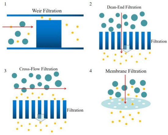
Weir-type microfiltration requires more steps in fabrication. To make a weir structure, additional soft lithography and etching processes are needed. Commonly, weir-type microfiltration can handle a limited amount of whole blood due to its tiny pore area compared to other types of microfiltration. Dead-end microfiltration mainly uses pore structures that are smaller than the blood cells dimensions to block blood cells and let the plasma continuously flow downstream. Once the blood cells accumulated and block all the pores, the microchannel will be clogged and stop separating plasma from whole blood. Cross-flow microfiltration can handle much more amount of whole blood. Due to the pillar filter structures or the pores on a membrane of the cross-flow microfiltration are located perpendicular to the main blood flow, blood cells could be easily removed by the main flow and not block the filtration pores. Lastly, membrane filtration is usually overpriced. The separation efficiency is mediocre, but the cost is high. In addition, it’s hard to control the pore size precisely and lead to a disappointing separation result.

3. Passive Self-Separation without Filtration

Due to the complicated balance of hydrodynamic forces, particles suspended in the microfluidic flow could be sorted by their sizes and densities. In a spiral microchannel, the flow experiences a centrifugal force when passing through the curved channel. The fluid on the outer side of the channel has a relatively higher pressure and forms a pressure gradient toward the center of the curvature of the curved channel. In a viscous flow, the velocity profile is not uniform. The velocity near the channel wall is lower than in the center of the channel and causes a lower centrifugal force on the outer channel wall. This will cause a secondary flow from the channel center to the outer channel wall. Meanwhile, due to the pressure gradient from the outer side to the curvature center, a flow will flow along the channel wall from the convex wall to the concave wall. These secondary flows formed a pair of symmetric vortices is called Dean vortices [67][68].
Particles suspended in the spiral microchannel experience the inertial lift force caused by the microchannel cross-section and the dean drag force due to the Dean vortices, shown in Figure 4. Inertial lift force:
where ρ is the fluid density, G is the shear rate, CL is the lift coefficient, ap is the diameter of the particle. The Dean drag force:
where μ is the viscosity of the fluid, UD is the average Dean velocity UD = 1.8 × 10⁴ De1.63 (De is Dean number De = Re(Dh/2R)0.5, Re is Reynolds number, Dh is hydraulic diameter, R is the radius of the curvature of the convex channel wall). The particles or cells will migrate to a focus position when the dean drag force and the inertial lift force are balanced [69].
Figure 4. Schematic illustrating the effect of the curvature, the larger particles focus on the position closer to the inner channel wall due to the dean vortex.
Sedimentation is one of the oldest separation approaches based on gravity and the density differences between plasma and blood cells (ρRBCs=1100 kg/m3, ρWBCS= 1050–1090 kg/m3 and ρplasma=1030 kg/m3), the principle is shown in Figure 5. Sedimentation velocity of blood cells in the whole blood is varied with patients’ sex and health conditions [70]. The biggest limitation of sedimentation technology is the low separation velocity, and it is out of consideration when facing a large volume of the blood sample. However, with a small amount of blood, such as finger prick, it is still a popular technology. Hybridizing the sedimentation technique with filtration advantageously minimizes clogging issues inherent to microfiltration [71][72]. Most blood cells sediment before reaching the filtration region, the plasma could be continuously extracted and a few suspension blood cells are separated away by the filter.
Figure 5. Schematic of sedimentation technique.
Bifurcation law also called the Zweifach-Fung effect, describes when the blood flowing in the capillary and passing through a bifurcating region, the RBCs in the blood flow into the higher flow rate daughter vessel. In contrast, only a few RBCs flow into the lower flow rate daughter vessel [73]. This effect will occur when the flow rate ratio between two daughter channels is above the critical ratio: 2.5:1. The diameter of the channel wall should not be too much larger than the diameter of cells [74]. As Figure 6 shows, at the bifurcation region, the asymmetric shear forces are applied on the cell’s surface due to the flow rate difference and produce a torque to pull it into the high flow rate channel [75].
Figure 6. Zweifach-Fung effect schematic diagram, when the flow rate ratio is more than 2.5, and the cell-to-vessel diameter ratio is of the order of 1. Red blood cells tend to flow into the higher flow rate daughter vessel instead of, the lower flow rate daughter vessel due to the pressure difference and shear forces acting on the cell [74]. Republished with permission of the Royal Society of Chemistry, from Lab on a Chip, A microfluidic device for continuous, real-time blood plasma separation, Sung Yang, Akif Ündar and Jeffrey D. Zahn, 6, 871-880, 2006; permission conveyed through Copyright Clearance Center, Inc.
The passive self-separation microfluidic channel’s blood flow is driven by capillary force induced by hydrophilic channel walls [76]. Researchers designed a microchannel with different hydrophilicity patterns to separate plasma based on this principle, as can be appreciated in Figure 7 that shows. Asymmetric channel with 3 sides hydrophilic in the front part of the channel and a hydrophobic patch with all walls hydrophobic is applied followed with the hydrophilic part. When the blood sample is introduced into the channel inlet, with the hydrophilic channel walls and Young-Laplace pressure, the blood flow into the microchannel as a capillary-driven flow. With the large contact angle and the inverse direction Young-Laplace pressure, the blood flow is impeded at the hydrophobic region. Since the viscosities of blood plasma and blood cells are different, the plasma has a higher velocity in the hydrophobic patch than the blood cells and passes through the hydrophobic region. Meanwhile, the blood cells stop and accumulated. In this technique, the asymmetric hydrophilic channel walls provide a gentler velocity decrease when the whole blood flow downstream [77], and the velocity could be controlled by the contact angle of the channel walls [78].
Figure 7. Schematic of surface control of wettability.

4. Future Trends

The passive blood-plasma self-separation technique is a possible candidate for LOC applications and overcomes many blood plasma separation challenges. For instance, the passive self-separation techniques can effectively avoid complex fabrications and easy to use in combination to overcome each other’s limitations. However, in the POCT applications, the exact sample provided by patients will restrict the separation methodologies. For example, the techniques based on the dean vortex are hard to satisfy the situation which required finger-prick amount of blood sample because the channel volumes are usually larger than finger-prick blood sample volumes. However, sedimentation technology with capillary flow actuation is fit for this application. To separate capillary volumes of blood, slow separation rates could be negligible compared to their performance. Additionally, the micro-filtration structures integrated into the sedimentation device could improve the clogging issue and increase the volumes of extracted plasma.
Even though numerous novel devices have been developed based on various technologies, nearly none has been considered commercially. The LOC community has been searching for effective and efficient microfluidic plasma separators in the past years, especially which could process undiluted blood. Yet, they have not been very successful until now. The viability of commercialization of microfluidic separation devices is affected by many aspects, such as the material choice for the microfluidic platform, the difficulty of the large scale of fabrication with PDMS, the reliable surface treatment process, commercial packaging should also be considered. Another limitation of the POC device commercialization is the patient’s operation of the devices. As a non-professional, patients are hard to precisely acquire the required amount of blood from finger prick as instructed. In the at-home sampling process, anti-coagulation of blood should also be considered [79]. Non-medical trained individuals usually do not know the coagulation process of the extracted blood. The anticoagulants should be precoated in the blood collection devices depending on the purpose of the POC devices. Additionally, they often lack an understanding of quality control. The misoperation may lead to inaccurate results. The sample volumes of blood plasma separation are categorized depending on the different purposes. For the small amount of blood from finger-pricks, sedimentation with micro-filtration could be first considered, but hydrodynamic techniques may not have a good performance. In contrast, to process a large sample volume of hundreds of microliters, hydrodynamic techniques could address multiple challenges of other methods. Furthermore, a non-diluted blood sample is desired in commercial use, especially in POCT applications. However, most current techniques use diluted blood samples and the separation efficiency increases with the blood dilution level. Therefore, to use undiluted blood in microfluidic devices, a better understanding of blood flow in the microchannel is needed. The designers can have a better overview and abilities to improve the current technologies and promote the commercial use of the passive plasma separation platform. The future of the field of blood plasma separation is in the trend of hybridization of technologies. By combining techniques and taking advantage of distinct effects, designers can overcome challenges based on their design purposes.

References

  1. Nunna, B.B.; Lee, E.S. Point-of-Care (POC) Micro Biochip for Cancer Diagnostics. In TechConnect Briefs 2017: Biomaterials and Biomedical, Proceedings of the TechConnect World Innovation Conference and Expo, Washington, DC, USA, 14–17 May 2017; Diagnostics and Bioimaging; Taylor Francis: Washington, DC, USA, 2017; Volume 3, Chapter 4; pp. 110–113. ISBN 978-0-9988782-0-1.
  2. Nunna, B.B.; Mandal, D.; Lee, J.U.; Zhuang, S.; Lee, E.S. Sensitivity Study of Cancer Antigens (CA-125) Detection Using Interdigitated Electrodes Under Microfluidic Flow Condition. BioNanoScience 2019, 9, 203–214.
  3. Nunna, B.B.; Mandal, D.; Zhuang, S.; Lee, E.S. A standalone micro biochip to monitor the cancer progression by measuring cancer antigens as a point-of-care (POC) device for enhanced cancer management. In Proceedings of the 2017 IEEE Healthcare Innovations and Point of Care Technologies (HI-POCT), Bethesda, MD, USA, 6–8 November 2017; pp. 212–215.
  4. Singh, H.; Zhuang, S.; Ingis, B.; Nunna, B.B.; Lee, E.S. Carbon-Based Catalysts for Oxygen Reduction Reaction: A Review on Degradation Mechanisms. Carbon 2019, 151, 160–174.
  5. Singh, H.; Zhuang, S.; Nunna, B.B.; Lee, E.S. Thermal Stability and Potential Cycling Durability of Nitrogen-Doped Graphene Modified by Metal-Organic Framework for Oxygen Reduction Reactions. Catalysts 2018, 8, 607.
  6. Zhuang, S.; Singh, H.; Nunna, B.B.; Mandal, D.; Boscoboinik, J.A.; Lee, E.S. Nitrogen-doped graphene-based catalyst with metal-reduced organic framework: Chemical analysis and structure control. Carbon 2018, 139, 933–944.
  7. Zhuang, S.; Nunna, B.B.; Lee, E.S. Metal-organic framework-modified nitrogen-doped graphene oxygen reduction re-action catalyst synthesized by nanoscale high-energy wet ball-milling structural and electrochemical characterization. MRS Commun. 2017, 8, 40–48.
  8. Kersaudy-Kerhoas, M.; Sollier, E. Micro-scale blood plasma separation: From acoustophoresis to egg-beaters. Lab Chip 2013, 13, 3323.
  9. Mahmoudi, G.; Babashkina, M.G.; Maniukiewicz, W.; Afkhami, F.A.; Nunna, B.B.; Zubkov, F.I.; Ptaszek, A.L.; Szczepanik, D.W.; Mitoraj, M.P.; Safin, D.A. Solvent-Induced Formation of Novel Ni(II) Complexes Derived from Bis-Thiosemicarbazone Ligand: An Insight from Experimental and Theoretical Investigations. Int. J. Mol. Sci. 2021, 22, 5337.
  10. Zhuang, S.; Nunna, B.B.; Mandal, D.; Lee, E.S. A Review of Nitrogen-Doped Graphene Catalysts for Proton Exchange Membrane Fuel Cells-Synthesis, Characterization, and Improvement. Nano-Struct. Nano-Objects 2017, 15, 140–152.
  11. Singh, H.; Zhuang, S.; Nunna, B.B.; Lee, E.S. Morphology and Chemical Structure of Modified Nitrogen-Doped Graphene for Highly Active Oxygen Reduction Reactions. In Proceedings of the 48th Power Source Conference, Denver, CO, USA, 11–14 June 2018.
  12. Nunna, B.B.; Zhuang, S.; Lee, E.S. Influence on Capillary Flow of Human Blood in PDMS Micro Channels due to various Surface Treatments, (ICNMM2016-8122). In Proceedings of the ASME 14th Int’l Conference on Nano-channels, Microchannels and Minichannels (ICNMM), Washington, DC, USA, 10–14 July 2016.
  13. Zhuang, S.; Nunna, B.B.; Boscoboinik, J.A.; Lee, E.S. Nitrogen-doped graphene catalysts: High energy wet ball milling synthesis and characterizations of functional groups and particle size variation with time and speed. Int. J. Energy Res. 2017, 41, 1–19.
  14. Mandal, D.; Nunna, B.B.; Zhuang, S.; Rakshit, S.; Lee, E.S. Carbon Nanotubes Based Biosensor for Detection of Cancer Antigens (CA-125) Under Shear Flow Condition. Nano-Struct. Nano-Objects 2017, 15, 180–185.
  15. Nunna, B.B.; Mandal, D.; Zhuang, S.; Lee, E.S. Innovative Point-of-Care (POC) Micro Biochip for Early Stage Ovarian Cancer Diagnostics. Sens. Transducers J. 2017, 214, 12–20.
  16. Zhuang, S.; Lei, L.; Nunna, B.B.; Lee, E.S. New Nitrogen-Doped Graphene/MOF-modified catalyst for Fuel Cell Systems. ECS Trans. 2016, 72, 149–154.
  17. Zhuang, S.; Lee, E.S.; Lei, L.; Nunna, B.B.; Kuang, L.; Zhang, W. Synthesis of Nitrogen-Doped Graphene Catalyst by High-Energy Wet Ball Milling for Electrochemical Systems. Int. J. Energy Res. 2016, 40, 2136–2149.
  18. Huang, C.-J.; Chen, Y.-H.; Wang, C.-H.; Chou, T.-C.; Lee, G.-B. Integrated microfluidic systems for automatic glucose sensing and insulin injection. Sens. Actuators B Chem. 2007, 122, 461–468.
  19. Pei, J.; Tian, F.; Thundat, T. Glucose Biosensor Based on the Microcantilever. Anal. Chem. 2004, 76, 292–297.
  20. Koczula, K.M.; Gallotta, A. Lateral flow assays. Essays Biochem. 2016, 60, 111–120.
  21. Oh, Y.K.; Joung, H.-A.; Kim, S.; Kim, M.-G. Vertical flow immunoassay (VFA) biosensor for a rapid one-step immunoassay. Lab Chip 2013, 13, 768.
  22. Liu, S.; Su, W.; Ding, X. A Review on Microfluidic Paper-Based Analytical Devices for Glucose Detection. Sensors 2016, 16, 2086.
  23. Arif, T.M.; Ji, Z.; Rahim, M.A.; Nunna, B.B. Modeling Focused-Ultrasound Response for Non-Invasive Treatment Using Machine Learning. Bioengineering 2021, 8, 74.
  24. Turgeon, M.L. Clinical Hematology: Theory and Procedures; Lippincott Williams & Wilkins: Philadelphia, PA, USA, 2005.
  25. Paulus, J. Platelet size in man. Blood 1975, 46, 321–336.
  26. Lewis, S.M.; Bain, B.J.; Bates, I.; Dacie, J.V. Dacie and Lewis Practical Haematology; Churchill Livingstone/Elsevier: London, UK, 2006.
  27. Fung, Y.C. 1981 Biomechanics—Mechanical Properties of Living Tissues; Springer: New York, NY, USA, 1993.
  28. Nunna, B.B.; Mandal, D.; Lee, J.U.; Singh, H.; Zhuang, S.; Misra, D.; Bhuyian, N.U.; Lee, E.S. Detection of Cancer Antigens (CA-125) using Gold Nano Particles on Interdigitated Electrode based Microfluidic Biosensor. Nano Converg. 2019, 6.
  29. Nunna, B.B.; Mandal, D.; Lee, J.U.; Zhuang, S.; Lee, E.S. Hemorheology in PDMS Microchannel with Varied Surface Roughness APS Meeting Abstracts 2015. Available online: https://ui.adsabs.harvard.edu/abs/2015APS..DFDKP1116N/abstract (accessed on 3 July 2021).
  30. Nunna, B.B.; Zhuang, S.; Javier, J.; Mandal, D.; Lee, E.S. Biomolecular Detection using Molecularly Imprinted Polymers (MIPs) at Point-of-Care (POC) Micro Biochip. In Proceedings of the 2016 IEEE-NIH 2016 Healthcare Innovation Point of Care Technologies Conference HI POCT16, (PCHT16-0099), Cancun, Mexico, 9–11 November 2016.
  31. Zhuang, S.; Nunna, B.B.; Lei, L.; Lee, E.S. Synthesis of Nitrogen-doped Graphene Catalyst by Wet Ball Milling for Electrochemical Systems, (Paper ID: 2425505). In Proceedings of the 251st ACS National Meeting Exposition, San Diego, CA, USA, 13–17 March 2016.
  32. Nunna, B.B.; Zhuang, S.; Malave, I.; Lee, E.S. Ovarian Cancer Diagnosis using Micro Biochip. In Proceedings of the NIH-IEEE 2015 Strategic Conference on Healthcare Innovations and Point-of-Care Technologies for Precision Medicine, (PCHT15-0056), Bethesda, MD, USA, 9–10 November 2015.
  33. Lee, E.S.; Nunna, B.B.; Suh, S.K. Microfluidic Diagnostic Assembly. U.S. Patent and Trademark Office. U.S. Patent US10898894B2, 26 January 2021. Available online: https://patents.google.com/patent/US10898894B2/en. (accessed on 3 July 2021).
  34. Lee, E.S.; Nunna, B.B. Biomarker Detection and Self-Separation of Serum During Capillary Flow. U.S. Patent and Trademark Office. U.S. Patent US10481154B2, 19 November 2019. Available online: https://patents.google.com/patent/US10481154B2/en. (accessed on 3 July 2021).
  35. Lee, E.S.; Nunna, B.B. Enhanced Sensitivity and Specificity for Point-Of-Care (POC) Micro Biochip. U.S. Patent and Trademark Office. U.S. Patent US20200182864A1, 11 June 2020. Available online: https://patents.google.com/patent/US20200182864A1/en. (accessed on 3 July 2021).
  36. Lee, E.S.; Nunna, B.B. Microfluidic Biochip with Enhanced Sensitivity. U.S. Patent and Trademark Office. U.S. Patent US11020740B2, 1 June 2021. Available online: https://patents.google.com/patent/US11020740B2/en. (accessed on 3 July 2021).
  37. Yang, C.-H.; Hsieh, Y.-L.; Tsou, P.-H.; Li, B.-R. Thermopneumatic suction integrated microfluidic blood analysis system. PLoS ONE 2019, 14, e0208676.
  38. Laurell, T.; Petersson, F.; Nilsson, A. Chip integrated strategies for acoustic separation and manipulation of cells and particles. Chem. Soc. Rev. 2007, 36, 492–506.
  39. Lenshof, A.; Laurell, T. Continuous separation of cells and particles in microfluidic systems. Chem. Soc. Rev. 2010, 39, 1203.
  40. Das, C.M.; Becker, F.; Vernon, S.; Noshari, J.; Joyce, C.; Gascoyne, P.R. Dielectrophoretic Segregation of Different Human Cell Types on Microscope Slides. Anal. Chem. 2005, 77, 2708–2719.
  41. Szydzik, C.; Khoshmanesh, K.; Mitchell, A.; Karnutsch, C. Microfluidic platform for separation and extraction of plasma from whole blood using dielectrophoresis. Biomicrofluidics 2015, 9, 064120.
  42. Nakashima, Y.; Hata, S.; Yasuda, T. Blood plasma separation and extraction from a minute amount of blood using dielectrophoretic and capillary forces. Sens. Actuators 2010, 145, 561–569.
  43. Macdonald, M.P.; Spalding, G.C.; Dholakia, K. Microfluidic sorting in an optical lattice. Nature 2003, 426, 421–424.
  44. Huh, D.; Bahng, J.H.; Ling, Y.; Wei, H.-H.; Kripfgans, O.D.; Fowlkes, J.B.; Grotberg, J.B.; Takayama, S. Gravity-Driven Microfluidic Particle Sorting Device with Hydrodynamic Separation Amplification. Anal. Chem. 2007, 79, 1369–1376.
  45. Lee, B.S.; Lee, J.-N.; Park, J.-M.; Lee, J.-G.; Kim, S.; Cho, Y.-K.; Ko, C. A fully automated immunoassay from whole blood on a disc. Lab Chip 2009, 9, 1548.
  46. Jung, J.; Han, K.-H. Lateral-driven continuous magnetophoretic separation of blood cells. Appl. Phys. Lett. 2008, 93, 223902.
  47. Liao, S.-H.; Chang, C.-Y.; Chang, H.-C. A capillary dielectrophoretic chip for real-time blood cell separation from a drop of whole blood. Biomicrofluidics 2013, 7, 024110.
  48. Yan, S.; Zhang, J.; Alici, G.; Du, H.; Zhu, Y.; Li, W. Isolating plasma from blood using a dielectrophoresis-active hydrophoretic device. Lab Chip 2014, 14, 2993.
  49. Yeo, L.Y.; Friend, J.R.; Arifin, D.R. Electric tempest in a teacup: The tea leaf analogy to microfluidic blood plasma separation. Appl. Phys. Lett. 2006, 89, 103516.
  50. Li, Y.; Dalton, C.; Crabtree, H.J.; Nilsson, G.; Kaler, K.V. Continuous dielectrophoretic cell separation microfluidic device. Lab Chip 2007, 7, 239–248.
  51. Grady, M.; Pineau, M.; Pynes, M.K.; Katz, L.B.; Ginsberg, B. A Clinical Evaluation of Routine Blood Sampling Practices in Patients with Diabetes. J. Diabetes Sci. Technol. 2014, 8, 691–698.
  52. Colace, T.V.; Tormoen, G.W.; Mccarty, O.J.T.; Diamond, S.L. Microfluidics and Coagulation Biology. Annu. Rev. Biomed. Eng. 2013, 15, 283–303.
  53. Ingis, B.; Lee, E.S. 3D Printing for Whole Blood Filters Designed for Simple Integration with a Variety of Sensor Platforms. In Proceedings of the IEEE-NIH 2019 Healthcare Innovations and Point-of-Care Technologies (HI-POCT2019), Bethesda, MD, USA, 20–22 November 2019.
  54. Warkiani, M.E.; Tay, A.K.P.; Guan, G.; Han, J. Membrane-less microfiltration using inertial microfluidics. Sci. Rep. 2015, 5, 11018.
  55. Pamme, N. Continuous flow separations in microfluidic devices. Lab Chip 2007, 7, 1644.
  56. Meena, G.G.; Jain, A.; Parks, J.W.; Stambaugh, A.; Patterson, J.L.; Hawkins, A.R.; Schmidt, H. Integration of sample preparation and analysis into an optofluidic chip for multi-target disease detection. Lab Chip 2018, 18, 3678–3686.
  57. Lee, K.K.; Ahn, C.H.T. A new on-chip whole blood/plasma separator driven by asymmetric capillary forces. Lab Chip 2013, 13, 3261.
  58. Bellanger, H.; Darmanin, T.; Taffin De Givenchy, E.; Guittard, F. Chemical and Physical Pathways for the Preparation of Superoleophobic Surfaces and Related Wetting Theories. Chem. Rev. 2014, 114, 2694–2716.
  59. Ji, H.M.; Samper, V.; Chen, Y.; Heng, C.K.; Lim, T.M.; Yobas, L. Silicon-based microfilters for whole blood cell separation. Biomed. Microdevices 2008, 10, 251–257.
  60. Nam, Y.; Kim, M.; Kim, T. Pneumatically controlled multi-level microchannel for separation and extraction of microparticles. Sens. Actuators Chem. 2014, 190, 86–92.
  61. Wilding, P.; Kricka, L.J.; Cheng, J.; Hvichia, G.; Shoffner, M.A.; Fortina, P. Integrated cell isolation and polymerase chain reaction analysis using silicon microfilter chambers. Anal. Biochem. 1998, 257, 95–100.
  62. Zheng, S.; Lin, H.; Liu, J.-Q.; Balic, M.; Datar, R.; Cote, R.J.; Tai, Y.-C. Membrane microfilter device for selective capture, electrolysis and genomic analysis of human circulating tumor cells. J. Chromatogr. A 2007, 1162, 154–161.
  63. Vandelinder, V.; Groisman, A. Separation of Plasma from Whole Human Blood in a Continuous Cross-Flow in a Molded Microfluidic Device. Anal. Chem. 2006, 78, 3765–3771.
  64. Didar, T.F.; Li, K.; Tabrizian, M.; Veres, T. High throughput multilayer microfluidic particle separation platform using embedded thermoplasticbased micropumping. Lab Chip 2013, 13, 2615.
  65. Didar, T.F.; Li, K.; Veres, T.; Tabrizian, M. Separation of rare oligodendrocyte progenitor cells from brain using a high-throughput multilayer thermoplastic-based microfluidic device. Biomaterials 2013, 34, 5588–5593.
  66. Hosokawa, M.; Yoshikawa, T.; Negishi, R.; Yoshino, T.; Koh, Y.; Kenmotsu, H.; Naito, T.; Takahashi, T.; Yamamoto, N.; Kikuhara, Y.; et al. Microcavity Array System for Size-Based Enrichment of Circulating Tumor Cells from the Blood of Patients with Small-Cell Lung Cancer. Anal. Chem. 2013, 85, 5692–5698.
  67. Dean, W.R., XVI. Note on the motion of fluid in a curved pipe. Lond. Edinb. Dublin Philos. Mag. J. Sci. 1927, 4, 208–223.
  68. Dean, W.R. The stream-line motion of fluid in a curved pipe (Second paper). Lond. Edinb. Dublin Philos. Mag. J. Sci. 1928, 5, 673–695.
  69. Nivedita, N.; Papautsky, I. Continuous separation of blood cells in spiral microfluidic devices. Biomicrofluidics 2013, 7, 054101.
  70. Brigden, M.L. Clinical utility of the erythrocyte sedimentation rate. Am. Fam. Physician. 1999, 60, 1443–1450.
  71. Huang, C.-T.; Li, P.-N.; Pai, C.-Y.; Leu, T.-S.; Jen, C.-P. Design and Simulation of a Microfluidic Blood-Plasma Separation Chip Using Microchannel Structures. Sep. Sci. Technol. 2009, 45, 42–49.
  72. Dimov, I.K.; Basabe-Desmonts, L.; Garcia-Cordero, J.L.; Ross, B.M.; Ricco, A.J.; Lee, L.P. Stand-alone self-powered integrated microfluidic blood analysis system (SIMBAS). Lab Chip 2011, 11, 845–850.
  73. Fung, Y.C.; Zweifach, B.W. Microcirculation: Mechanics of Blood Flow in Capillaries. Annu. Rev. Fluid Mech. 1971, 3, 189–210.
  74. Yang, S.; Undar, A.; Zahn, J.D. A microfluidic device for continuous, real time blood plasma separation. Lab Chip 2006, 6, 871–880.
  75. Xue, X.; Patel, M.K.; Kersaudy-Kerhoas, M.; Bailey, C.; Desmulliez, M.P. Parametrical modeling and design optimization of blood plasma separation device with microchannel mechanism. In Proceedings of the 59th Electronic Components and Technology Conference 2009, San Diego, CA, USA, 26–29 May 2009; pp. 1970–1976.
  76. Nunna, B.B.; Zhuang, S.; Lee, E.S. Flow control mechanism of capillary driven flow in microchannel using non-mechanical forces. In Proceedings of the Aps Division of Fluid Dynamics abstract id. A25.002, Portland, OR, USA, 20–26 November 2016.
  77. Pitt, W.G.; Alizadeh, M.; Blanco, R.; Hunter, A.K.; Bledsoe, C.G.; McClellan, D.S.; Beard, W.C.; Jacob, R.S.; Carter, A.; Anderson, C.M.; et al. Factors affecting sedimentational separation of bacteria from blood. Biotechnol. Prog. 2020, 36, e2892.
  78. Maria, M.S.; Rakesh, P.E.; Chandra, T.S.; Sen, A.K. Capillary flow of blood in a microchannel with differential wetting for blood plasma separation and on-chip glucose detection. Biomicrofluidics 2016, 10, 054108.
  79. Shaw, J.L.V. Practical challenges related to point of care testing. Pract. Lab. Med. 2016, 4, 22–29.
More
Information
Contributor MDPI registered users' name will be linked to their SciProfiles pages. To register with us, please refer to https://encyclopedia.pub/register :
View Times: 830
Revision: 1 time (View History)
Update Date: 12 Jul 2021
1000/1000