 +1 credit
| Version | Summary | Created by | Modification | Content Size | Created at | Operation |
|---|---|---|---|---|---|---|
| 1 | Nader Asnafi | + 1569 word(s) | 1569 | 2021-03-29 11:21:38 | | | |
| 2 | Vicky Zhou | -4 word(s) | 1565 | 2021-03-30 10:56:52 | | | | |
| 3 | Vicky Zhou | -4 word(s) | 1565 | 2021-03-30 10:57:25 | | | | |
| 4 | Vicky Zhou | Meta information modification | 1565 | 2021-03-30 10:57:57 | | | | |
| 5 | Vicky Zhou | Meta information modification | 1565 | 2021-03-30 10:58:30 | | | | |
| 6 | Vicky Zhou | Meta information modification | 1565 | 2021-03-30 10:59:06 | | |
Video Upload Options
Laser-based powder Bed Fusion (L-PBF), formerly SLM, is one of the seven Additive Manufacturing basic process categories in the new standards.
1. Introduction
During the past 15 years, layered manufacturing has been subject to further research studies, standardization and industrialization. According to the developed standards, the technology is named Additive Manufacturing (AM). Laser-based powder Bed Fusion (L-PBF), formerly SLM, is one of the seven AM basic process categories in the new standards [1][2][3][4]. For a detailed description of L-PBF, see [5][6][7][8][9].
Table 1 displays the features of the current (2020) machines for AM by L-PBF. This table, which is based on the machine makers specifications, shows that the maximum object size that can be 3D-printed today is 600 × 600 × 600 mm3 (although the largest height is 850 mm in one of the other machines). This size has more than doubled compared to that in the 1995 machine for selective laser sintering. In addition to higher laser power, some of the current machines have more than one laser and therefore a much higher productivity.
Due to the complexity of L-PBF, the manufacturers of metal AM systems have developed sets of optimized processing conditions for some existing powder metals. The machine manufacturer sets the process parameters for one or some specific powder metals as the default values for additive manufacturing based on the customer preferences before machine delivery and installation, Table 2. The number of these powder metals is much larger than those in 1995. However, this number is still very small, compared to the number of existing materials made and used conventionally.
Table 1. The features of the current L-PBF machines [10][11][12][13][14][15][16].
| Manufacturer | Model | Number and Type of Lasers | Laser Power (per Laser) (W) |
Build Volume (l × w × h) (mm3) |
Build Rate (cm3/hr) |
Layer Thickness (μm) |
Scan Speed (m/s) |
|---|---|---|---|---|---|---|---|
| 3D Systems | DMP Factory 500 Printer Module | 3 fiber | 500 | 500 × 500 × 500 1 | - | 2–200, Typical: 30, 60 & 90 | - |
| DMP Factory/Flex 350 | 1 fiber | 500 | 275 × 275 × 420 | - | 5–200, Typical: 30, 60 & 90 | - | |
| DMP Flex 100 | 1 fiber | 100 | 100 × 100 × 90 | - | 10–100 | - | |
| ProX DMP 300 | 1 fiber | 500 | 250 × 250 × 330 | - | 10–100, preset: 40 | - | |
| ProX DMP 200 | 1 fiber | 300 | 140 × 140 × 115 | - | 10–100, preset: 30 | - | |
| Additive Industries |
MetalFAB1 | 1 to 4 Yb fiber | 500 | 420 × 420 × 400 | - | 20–100 | - |
| Concept Laser | X Line 2000R | 2 (cw) fibre | 1000 | 800 × 400 × 500 | - | - | - |
| M Line Factory | 4 fiber | 1000 | 500 × 500 × 400 | - | - | - | |
| M2 Multilaser | 2 (cw) fiber | 400 | 250 × 250 × 350 | - | - | - | |
| EOS | EOS M 400-4 | 4 Yb-fiber | 400 | 400 × 400 × 400 1 | 100 | 80 | 7 |
| EOS M 400 | 1 Yb-fiber | 400 | 400 × 400 × 400 1 | 50 | - | 7 | |
| EOS M 300-4 | 4 Yb-fiber | 400 | 300 × 300 × 400 | 10 | - | 7 | |
| EOS M 290 | 1 Yb-fiber | 400 | 250 × 250 × 325 1 | - | - | 7 | |
| EOS M 100 | 1 Yb-fiber | 200 | f100 × 95 1 & 2 | - | - | 7 | |
| SLM Solutions | SLM®NXG XII 600 | 12 | 1000 | 600 × 600 × 600 | 1000 | - | - |
| SLM®800 | 4 | 400 or 700 | 500 × 280 × 850 1 | Up to 171 | 20–90 | 10 | |
| SLM®500 | 4 IPG fiber | 700 | 500 × 280 × 365 1 | Up to 171 | 20–75 | 10 | |
| SLM®280 | 1, 2, 3 or dual | 400, 700, or 700 & 1000 | 280 × 280 × 365 1 | Up to 113 | 20–90 | 10 | |
| SLM®125 | 1 IPF fiber | 400 | 125 × 125 × 125 1 | Up to 25 | 20–75 | 10 | |
| Renishaw | RenAM 500Q/S | 1 or 4 Yb-fiber | 500 | 250 × 250 × 350 1 | Up to 150 | 20–100 | 10 |
| RenAM 500E | 1 Yb-fiber | 500 | 250 × 250 × 350 1 | Up to 150 | 20–100 | 10 | |
| RenAM 500M | 1 Yb-fiber | 500 | 250 × 250 × 350 1 | Up to 150 | 20–100 | 10 | |
| AM 400 | 1 | 400 | 250 × 250 × 300 1 | - | - | - | |
| AM 250 | is now replaced by AM 400 | 250 × 250 × 300 1 | - | - | - | ||
| Trumpf | TruPrint 1000 | 1 fiber | 200 | f100 × 100 1 & 2 | 2–18 | 10–50 | - |
| TruPrint 2000 | 1 fiber | 300 | f200 × 200 2 | - | 20–100 | - | |
| TruPrint 3000 | 1 fiber | 500 | f300 × 400 2 | 5–60 | 20–150 | - | |
| TruPrint 5000 | 3 fiber | 500 | f300 × 400 2 | 5–180 | 30–150 | - | |
1 Height includes the thickness of the substrate/building plate. 2 Diameter × height.
Table 2. Materials the current machines L-PBF machines can be set in for upon installation [10][11][12][13][14][15][16].
| Manu- facturer |
Model | Powder Metals Based on… | ||||||
|---|---|---|---|---|---|---|---|---|
| Al | Co | Cu | Fe | Ni | Ti | W | ||
| 3D Systems |
DMP Factory 500 Printer Module | By request | Nickel alloys | By request | ||||
| DMP Factory/Flex 350 | AlSi7Mg0.6, AlSi10Mg | CoCrF75 | - | Maraging Steel, 17-4PH, 316L | Ni625, Ni718 | Ti Gr1, Ti Gr5, Ti Gr23 | - | |
| DMP Flex 100 | - | CoCr | - | 17-4PH, 316L | - | - | - | |
| ProX DMP 300 | AlSi12 | CoCr | - | Maraging steel, 17-4PH | - | - | - | |
| ProX DMP 200 | AlSi12 | CoCr | - | Maraging steel, 17-4PH, 316 L | - | - | - | |
| Additive Industries | MetalFAB1 | AlSi10Mg, ScalmAlloy© | - | - | Tool steel 1.2709, 316L | IN718 | Ti6Al4V | - |
| Concept Laser | X Line 2000R | AlSi10Mg—Balanced & Productivity | - | - | - | Nickel 718 | Ti6AL4V Grade 23 | - |
| M Line Factory | A205 | CoCrMo | - | - | Nickel 718 CL | - | - | |
| M2 Multilaser | AlSi10Mg, AlSi7Mg | CoCrMo | - | Maraging M300, 316L, 17-4PH | Nickel 625, Nickel 718 | Ti6AL4V Grade 23 | - | |
| EOS | EOS M 400-4 | AlSi10Mg | - | - | MS1, 316L | HX, IN718 | Ti64, TiCP Grade 2 | - |
| EOS M 400 | AlSi10Mg | - | - | MS1 | IN718 | Ti64, Ti64ELI | - | |
| EOS M 300-4 | AlSi10Mg | - | - | MS1 | IN718 | Ti64 | - | |
| EOS M 290 | AlSi10Mg | MP1 | - | MS1, CX, PH1, 17-4PH, 316L | HX, IN625, IN718 | Ti64, Ti64ELI, TiCP Grade 2 | - | |
| EOS M 100 | - | SP2 | - | 316L | - | Ti64 | W1 | |
| SLM Solutions | SLM®NXG XII 600 | ALSi10Mg (No limitations) | No limitations | IN718 (No limit.) | No limitations | |||
| SLM®800 | AlSi10Mg, AlSi7Mg0.6, AlSi9Cu3 | CoCr28Mo6, SLM® MediDent | CuSn10, CuNi2SiCr | Maraging 1.2709, 316L (1.4404), 15-5PH (1.4545), 17-4PH (1.4542), H13 (1.2344), Invar 36® | HX, IN625, IN718, IN939 | Ti6Al4V ELI (Grade 23), TA15, and Ti (Grade 2) | - | |
| SLM®500 | ||||||||
| SLM®280 | ||||||||
| SLM®125 | ||||||||
| Renishaw | RenAM 500Q/S | AlSi10Mg | CoCr | - | Maraging M300, 316L | IN625, IN718 | Ti6Al4ELI | - |
| RenAM 500E | ||||||||
| RenAM 500M | ||||||||
| AM 400 | ||||||||
| AM 250 | ||||||||
| Trumpf | TruPrint 1000 | Yes to all except W + precious metal alloys + amorphous metals | ||||||
| TruPrint 2000 | Yes to all except Cu and W + amorphous metals | |||||||
| TruPrint 3000 | Yes to all except Co, Cu and W | |||||||
| TruPrint 5000 | Yes to all except Co, Cu and W | |||||||
2. Tool Design for Metal Additive Manufacturing by L-PBF
Additive manufacturing provides significantly larger design freedom (compared to conventional manufacturing), the benefits of which can be maximized by the emerging computer-aided design (CAD) technologies like generative design (GD). It is now possible to:
(1) Generate a wide range of design alternatives by artificial intelligence-based algorithms (GD software) after setting the part/object design space, constraints, criteria and objectives. The designer reviews the different design options and chooses the best-suited for the application [17][18].
(2) Topology optimize the selected design alternative, the purpose of which is to remove unnecessary material while meeting (or exceeding) the performance criteria. The goal is to optimize a part properly (weight, stiffness, frequency …) while respecting a certain set of constraints. The topology optimization process uses various mathematical algorithms and methods (each having several versions) [19][20][21][22].
(3) Optimize the internal lattice and surface structure of the topology optimized object by creating an internal mesh while meeting (or exceeding) the performance criteria [23][24][25][26].
(4) Produce this complex object by L-PBF (and post-processing).
During the past two decades, different new design methodologies have emerged, among them the Design for X (DfX). X represents a particular perspective to improve during the product design as well as the design process [27][28]. DfX applied to the Additive Manufacturing process is named DfAM. It aims at using the full potential of the AM technologies for design, for which there are two methods [18][29][30].
A new detailed DfAM process has been proposed including the available design support (methods, design rules, guidelines and software tools), the tools and methods that are best suited at different stages of the design process are specified, and the possibility to achieve a more automated DfAM is indicated [31].
As far as the L-PBF process design (i.e., the preparation of the L-PBF process) is concerned, the part orientation, support structures, overhangs and part supporting angles, channels and holes, wall thickness, tolerances and offsets are addressed in [32][33][34]. VDI 3405 Part 2, [32], addresses the qualification, quality assurance and post processing. The procedure described in this standard is applied to DIN 1.2709 in a VDI inter-laboratory test. The obtained properties in this inter-laboratory test are accounted for in [32].
The angle between the building platform and the building direction is also of great significance for the properties of the as-built object. In other words, the properties of the as-built object are anisotropic due to the layered manufacturing, the loading direction etc. Table 3 and Figure 1 display 7 different configurations, in which tensile specimens in 316L (1.4404) were built with an oversize of 0.4 mm in width and thickness. After milling to final shape, the specimens were tested. Table 4 displays the tensile properties of these specimens. The maximum strength is obtained at a 45° layer versus loading offset [35].
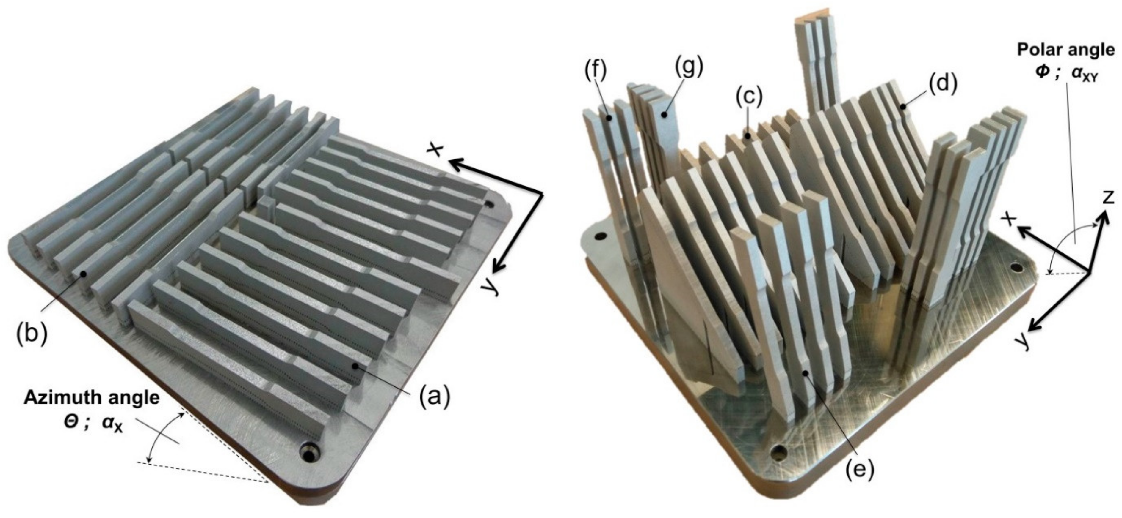
Figure 1. The tensile samples in 1.4404 (316L) on the building platform: overview of the positioning, building angles and arrangement (configurations). See also Table 3 and Table 4. The figure is from [35].
Table 3. The tested configurations. See also Figure 1 and Table 4. The table is from [35].
| Config. | Polar Angle Φ; αXY (°) | Azimuth Angle Θ; αX (°) | Total Runtime (h) |
|---|---|---|---|
| (a) | 0 | 0 | - |
| (b) | 0 | 90 | 39.5 |
| (c) | 15 | 0 | - |
| (d) | 45 | 0 | - |
| (e) | 75 | 0 | 86.5 |
| (f) | 90 | 0 | - |
| (g) | 90 | 90 | - |
Table 4. The tensile properties of 1.4404 (316L) in different building configurations. See also Table 3 and Figure 1. The specimens were built with an oversize of 0.4 mm in width and thickness and milled to final shape before tensile testing. The table is from [35].
| Config. | Young’s Modulus | Yield Strength | Ultimate Tensile | Elongation at | Poisson’s Ratio | |||||
|---|---|---|---|---|---|---|---|---|---|---|
| E (GPa) | Rp0.2 (MPa) | Strength Rm (MPa) | Failure At (%) | ν (-) | ||||||
| Average | STDEV | Average | STDEV | Average | STDEV | Average | STDEV | Average | STDEV | |
| (a) | 151.01 | 25.56 | 516.51 | 7.16 | 634.43 | 7.39 | 33.24 | 0.57 | 0.444 | 0.031 |
| (b) | 207.57 | 24.22 | 539.47 | 3.29 | 643.67 | 3.25 | 42.74 | 0.82 | 0.155 | 0.014 |
| (c) | 147.87 | 23.59 | 501.32 | 7.70 | 624.65 | 4.36 | 34.09 | 1.12 | 0.479 | 0.058 |
| (d) | 227.35 | 25.12 | 589.89 | 11.86 | 698.98 | 23.65 | 32.56 | 10.17 | 0.203 | 0.024 |
| (e) | 151.43 | 18.80 | 485.65 | 11.93 | 571.23 | 18.63 | 22.84 | 7.27 | 0.558 | 0.020 |
| (f) | 137.78 | 14.25 | 438.60 | 9.69 | 511.99 | 17.95 | 11.76 | 5.38 | 0.453 | 0.005 |
| (g) | 137.83 | 16.25 | 457.21 | 17.29 | 530.22 | 8.09 | 17.46 | 4.42 | 0.170 | 0.085 |
Design demands knowledge of the precise material properties. These properties are anisotropic and the component orientation on the build platform needs therefore to be considered [35]. (Post L-PBF heat treatment affects also these properties. See the properties of 316L (1.4404) before and after heat treatment)
It is possible to achieve ±0.2% in tolerance, with the minimal value being 0.2 mm. It is also possible to achieve a wall thickness of 0.5 mm. However, the wall shape is dependent upon the orientation, its height (in relation to the thickness), and the possibility to have support if needed. As far as gaps (between walls or solid portions) are concerned, the minimum gap width should be larger than at least the melt pool width. It is also important to add an allowance of 0.3–0.5 mm to the locations and surfaces that require post-processing by machining to reach the required tolerance and surface roughness [24][32].
References
- Sprinkle, T. The 5 Most Important Standards in Additive Manufacturing. ASTM Standardization News. 11 May 2020. Available online: (accessed on 25 November 2020).
- ISO. International Standard ISO 52900, 2016—Additive manufacturing—General principles—Terminology (ISO/ASTM 52900, 2015, IDT); ISO: Geneva, Switzerland, 2016.
- ISO. International Standard ISO 17296-2, 2016—Additive manufacturing—General principles—Part 2, Overview of process categories and feedstock (ISO 17296-2, 2015); ISO: Geneva, Switzerland, 2016.
- Ålgårdh, J.; Strondl, A.; Karlsson, S.; Farre, S.; Joshi, S.; Andersson, J.; Ågren, J. State-of-the-Art for Additive Manufacturing of Metals; Report 2016-03898—State-of-the-Art—Version 2.1; Swedish Arena for Additive Manufacturing of Metals: Stockholm, Sweden, 2017.
- Criales, L.E.; Arısoy, Y.M.; Lane, B.; Moylan, S.; Donmez, A.; Özel, T. Laser powder bed fusion of nickel alloy 625, Experimental investigations of effects of process parameters on melt pool size and shape with spatter analysis. Int. J. Mach. Tool Manuf. 2017, 121, 22–36.
- Schwarze, D. Auswirkungen der Bauraumvorheizung auf die thermomechanischen Bauteileigenschaften; Anwender Zentrum Augsburg, IWB: München, Germany, 2010.
- Over, C. Generative Fertigung von Bauteilen aus Werkzeugstahl X38CrMoV5-1 und Titan TiAl6V4 mit “Selective Laser Melting”; Shaker: Aachen, Germany, 2003.
- Niendorf, T.; Leuders, S.; Riemer, A.; Richard, H.A.; Tröster, T.; Schwarze, D. Highly Anisotropic Steel Processed by Selective Laser Melting. Metall. Mater. Trans. B 2013, 44B, 794–796.
- Langefeld, B.; Moehrle, M.; Balzer, C.; Schildbach, P. Advancements in Metal 3D Printing—Beyond Powder Bed—Additive Manufacturing on the Brink of Industrialization; Roland Berger: Munich, Germany, 2018.
- 3D Systems, Printers and Materials Specifications. Available online: (accessed on 27 November 2020).
- Additive Industries, Printers and Materials Specifications. Available online: (accessed on 27 November 2020).
- Concept Laser, Printers and Materials Specifications. Available online: (accessed on 27 November 2020).
- EOS (Electro Optical Systems), Printers and Materials Specifications. Available online: (accessed on 27 November 2020).
- SLM Solutions, Printers and Materials Specifications. Available online: (accessed on 27 November 2020).
- Renishaw, Printers and Materials Specifications. Available online: (accessed on 27 November 2020).
- Trumpf, Printers and Materials Specifications. Available online: (accessed on 27 November 2020).
- Krish, S. A practical generative design method. Comput. Aided Des. 2011, 43, 88–100.
- Briard, T.; Segonds, F.; Zamariola, N. G-DfAM: A methodological proposal of generative design for additive manufacturing in the automotive industry. Int. J. Interact. Des. Manuf. 2020, 14, 875–886.
- Bendsoe, M.P.; Sigmund, O. Topology Optimization: Theory, Methods and Applications; Springer: Berlin/Heidelberg, Germany, 2004.
- Liu, X.; Yi, W.J.; Li, Q.S.; Shen, P.S. Genetic evolutionary structural optimization. J. Constr. Steel Res. 2008, 64, 305–311.
- Zhao, F. A nodal variable ESO (BESO) method for structural topology optimization. Finite Elem. Anal. Des. 2014, 86, 34–40.
- Guo, X.; Zhang, W.; Zhang, J.; Yuan, J. Explicit structural topology optimization based on moving morphable components (MMC) with curved skeletons. Comput. Methods Appl. Mech. Eng. 2016, 310, 711–748.
- Niendorf, T.; Brenne, F.; Schaper, M. Lattice Structures Manufactured by SLM: On the Effect of Geometrical Dimensionson Microstructure Evolution During Processing. Metall. Mater. Trans. B 2014, 45B, 1181–1185.
- Schnabel, T.; Oettel, M.; Mueller, B.; Hoschke, K.; Pfaff, A.; Amund-Kopp, C.; Klöden, B.; Gebauer, M.; Töppel, T. Design for Additive Manufacturing, Guidelines and Case Studies for Metal Applications; Fraunhofer IWU, EMI and IFAM: Dresden, Germany, 2017.
- Pan, C.; Han, Y.; Lu, J. Design and Optimization of Lattuce Structures: A Review. Appl. Sci. 2020, 10, 6374.
- Dong, G.; Tang, Y.; Zhao, Y.F. A Survey of Modeling of Lattice Structures Fabricated by Additive Manufacturing. J. Mech. Des. 2017, 139, 100906.
- Kuo, T.C.; Huang, S.H.; Zhang, H.C. Design for manufacture and design for ‘X’: Concepts, applications, and perspectives. Comput. Ind. Eng. 2001, 41, 241–260.
- Tomiyama, T.; Gu, P.; Jin, Y.; Lutters, D.; Kind, C.; Kimura, F. Design methodologies: Industrial and educational applications. CIRP Ann. Manuf. Technol. 2009, 58, 543–565.
- Laverne, F.; Segonds, F.; Answer, N.; Le Coq, M. Assembly Based Methods to Support Product Innovation in Design for Additive Manufacturing: An Exploratory Case Study. J. Mech. Des. 2015, 137, 121701.
- Reiher, T.; Lindemann, C.; Jahnke, U.; Deppe, G.; Koch, R. Holistic approach for industrializing AM technology: From part selection to test and verification. Prog. Addit. Manuf. 2017, 2, 43–55.
- Wiberg, A.; Persson, J.; Ölvander, J. Design for additive manufacturing—A review of available design methods and software. Rapid Prototyp. J. 2019, 25, 1080–1094.
- VDI. VDI Guideline 3405 Part 2—Additive Manufacturing Processes, Rapid Manufacturing—Beam Melting of Metallic Parts—Qualification, Quality Assurance and Post Processing; VDI: Düsseldorf, Germany, 2013.
- International Standard ISO/ASTM 52911-1. Additive Manufacturing—Design—Part 1, Laser-Based Powder Bed Fusion of Metals; ISO: Geneva, Switzerland, 2019.
- Reinarz, B.; Sehrt, J.T.; Witt, G.; Deiss, O.; van Kampen, J.; Münzer, J.; Ott, M. Optimization of media feed channels in laser beam melting. Proc. ASPE. Berkeley 2014, 57, 13–18.
- Hitzler, L.; Hirsch, J.; Heine, B.; Merkel, M.; Hall, W.; Öchsner, A. On the Anisotropic Mechanical Properties of Selective Laser-Melted Stainless Steel. Materials 2017, 10, 1136.


