Submitted Successfully!
To reward your contribution, here is a gift for you: A free trial for our video production service.
Thank you for your contribution! You can also upload a video entry or images related to this topic.
Version Summary Created by Modification Content Size Created at Operation
1 -- 3211 2024-02-07 14:06:11 |
2 format change Meta information modification 3211 2024-02-08 02:37:06 |

Video Upload Options

Do you have a full video?

Confirm

Are you sure to Delete?
Cite
If you have any further questions, please contact Encyclopedia Editorial Office.
Vellwock, A.E.; Libonati, F. XFEM for Material Design. Encyclopedia. Available online: https://encyclopedia.pub/entry/54851 (accessed on 18 May 2024).
Vellwock AE, Libonati F. XFEM for Material Design. Encyclopedia. Available at: https://encyclopedia.pub/entry/54851. Accessed May 18, 2024.
Vellwock, Andre E., Flavia Libonati. "XFEM for Material Design" Encyclopedia, https://encyclopedia.pub/entry/54851 (accessed May 18, 2024).
Vellwock, A.E., & Libonati, F. (2024, February 07). XFEM for Material Design. In Encyclopedia. https://encyclopedia.pub/entry/54851
Vellwock, Andre E. and Flavia Libonati. "XFEM for Material Design." Encyclopedia. Web. 07 February, 2024.
XFEM for Material Design
Edit

The eXtended finite element method (XFEM) is a powerful tool for structural mechanics, assisting engineers and designers in understanding how a material architecture responds to stresses and consequently assisting the creation of mechanically improved structures. The XFEM method has unraveled the extraordinary relationships between material topology and fracture behavior in biological and engineered materials, enhancing peculiar fracture toughening mechanisms, such as crack deflection and arrest.

XFEM FEM fracture modeling composites biological materials bioinspiration AI

1. Introduction

The finite element method (FEM) has revolutionized material design by reducing redesign time and costs through prefabrication and structural optimization. The FEM facilitates the assessment of mechanical properties, such as the maximum load a bridge can withstand and where the failure point might be, and the number of cycles an automobile suspension can last before discontinuity. Understanding the fracture behavior (e.g., crack nucleation and propagation) is essential. Yet, the standard FEM cannot fully model fracture. In the last few decades, a few methods have emerged to cover this gap. Perhaps the first, after observation of stress around cracks [1], the contour integral method (CIM) and its variations have been proposed to calculate the stress intensity factor on cracked media [2][3]. Embedded on commercial software, and directly related to CIM, J-integral [4], CT-integral [5], and T-stress [6] are available. Despite clear advantages such as robustness, calculation speed, and simplicity, the CIM requires the modeling of the crack plane or line, specification of its front [7], and careful mesh preparation. Moreover, it gives only a step-wise output as it does not simulate the propagation path. The virtual crack closing technique (VCCT), developed in 1977 [8], calculates the energy release rate and propagation mode of a pre-defined crack. Besides, it can simulate the crack path on commercial software, an improvement from the CIM. However, the VCCT is a numerically challenging method and can only simulate brittle fracturing [9]. Thus, it is commonly employed on simpler models such as for delamination and debonding case studies. The cohesive zone element (CZM) [10][11][12] applies cohesive regions to understand non-linear behavior on the front of a pre-defined crack. The CZM also requires that the crack propagation path be pre-set. Despite moderate numerical convergence [13], these requirements limit its applicability to crack modeling. In this sense, the CZM, like the VCCT, is mainly utilized for debonding analyses [14][15][16]. The phase-field model (PFM) was introduced in 2008 [17], quickly followed by another publication in 2010 [18]. The PFM is surpassing the CIM, VCCT, and CZM because it employs a scalar field (i.e., the phase field) to smoothly transition from the intact to the damaged element and does not consider the crack as a physical discontinuity [19][20]. In addition, the PFM can model multiple cracks and their branching and merging [21]. However, issues such as diffuse damage profile due to regularization length are often encountered [22][23], requiring proper user input to overcome it [23]. Currently, the PFM’s direct implementation in commercial software is absent and requires user input subroutines [20][24][25], reducing its popularization among the fracture mechanics community. A summary of the pros and cons of numerical methods that can simulate fracture behavior is available in Table 1.
Table 1. Comparison of numerical methods that simulate fracture behavior.
The eXtended finite element method (XFEM) has been pushing the boundaries of fracture numerical analysis since its creation in 1999 [26]. The method is a powerful tool to simulate the fracture behavior of materials, elucidating the crack initiation and propagation under particular conditions. Frequently, the XFEM is applied to evaluate the influence of a material microstructure (e.g., different material properties and complex inner geometries) on the crack path, demonstrating hidden fracture toughness mechanisms and facilitating the design of mechanically superior materials. Naturally, composites are a direct application, where the XFEM can be used to alter the composite components towards a better material. In addition, biological and bioinspired materials have also been in the spotlight. Analyzing the fracture mode with the XFEM in biological materials, such as cortical bone and teeth, has not only allowed a better understating of the natural material mechanical characteristics but also the development of extraordinary bioinspired designs. These new architectures have been expanding the limits of structural materials by combining the usage of components with contrasting mechanical properties and creating complex innovative material designs.

2. XFEM and Composites

The XFEM has been applied to simulate fracture behavior in a variety of materials (Figure 1), ranging from rocks [30][31][32][33] to steel [34][35][36][37][38], cast iron [39][40], aluminum [41][42], silicon oxycarbide [43][44], and composites [45][46][47]. In the steel industry, the XFEM has been applied to better understand fatigue crack propagation on bridges [34], the impact properties of high-pressure gas transportation pipes [35], and the flexural response of coated steel used for yacht manufacturing [38]. Considering cast iron, Chang et al. [39] showed that the XFEM results were in great agreement with experimental uniaxial tests, demonstrating the material elastoplastic behavior. Applying a complex loading condition, with an eccentric impact load on a three-point bending cast iron structure, Tsuda et al. [40] highlighted the flexibility of the XFEM in uncommon cases. For an aluminum alloy sample, Gairola and Jayaganthan [41] correctly predicted the material fracture toughness, suggesting that 3D XFEM simulations are slightly better than 2D. Kim et al. [48] showed the effects of hydrogen gas on the fracture behavior of an aluminum alloy by simulating fracture resistance curves of compact tension specimens. The XFEM load and displacement curves were within 5% of the experimental conditions. Recently, Xie et al. [43] captured the mechanical and fracture behavior of a silicon carbide film, where the XFEM was a successful method for evaluating interfacial strength.
Figure 1. A diagram of XFEM usage in material simulations, highlighting its application to the field of biomaterials and bioinspired materials.
Composites is a growing field that is based on the design of materials with two or more components to create multi-material structures with particular mechanical properties. For example, the construction industry uses reinforced concrete as a load-bearing structure in the development of buildings [49]. Reinforced concrete refers to the use of aligned metallic bars in a concrete mix, where the bars play the essential role of increasing the composite’s overall load-bearing capacity. The modeling of columns made of reinforced concrete showed that the XFEM can predict the start location and growth pattern of cracks when the structure is subjected to monotonic or cyclic loadings [50][51]. Chung et al. [52] simulated a bending test of a reinforced concrete beam and demonstrated that the XFEM was able to initiate cracks in the majority of the locations experimentally observed. Moreover, the authors discussed problematics about the method’s convergence which were possibly accentuated by the choice of a 3D model over a simplified 2D. Marzec and Bobiński [53] studied the influence of cohesive softening law on XFEM simulations of concrete beams under bending. The authors applied three softening cases: bilinear, exponential, and a rational Bezier, concluding that all produced consistent results if different fracture energies are considered.
In the composite field, the method has been extensively used to study fiber-reinforced materials, such as in studies that evaluated the influence of random short fiber inclusions in composites, considering 2D [54] and 3D simulations [55]. Pike and Oskay [54] implemented a modified framework to understand the effect of random fiber inclusions, comparing the method to standard finite element modeling in case studies such as single fiber inclusion and random short fiber composites. In another study, Pike and Oskay [55] successfully showed that the influence of short fibers on composite materials can be modeled in a 3D simulation, rather than the previous 2D one. Serna Moreno et al. [56] showed that in bi-axial tensile tests of chopped glass-reinforced composites, the XFEM simulated crack start location, path, and even growth velocity in agreement with the experimental results. XFEM fatigue simulation on similar bi-axial samples demonstrated the capacity of the method to analyze fracture behavior under complex loads [57]. Fracturing is a large issue for composite structures. In thin plates where buckling can easily occur, the issue is also present. Simulations of cracks in composite plates using the XFEM facilitated the analysis of the crack lengths and angles, fiber directions, and even boundary conditions on overall structural behavior during buckling [58].
Delamination is one of the most crucial damages that can occur on impacted composites [59]. It refers to a de-adhesion of adjacent components, such as the peeling of a coating on a substrate and the detachment of fibers in a matrix. Despite a local effect, it can compromise the capacity of a whole structure to withstand loading. Carbon fiber composites and glass fiber-reinforced aluminum laminates are widely applied to the aerospace and high-end automotive industries. In this sense, Abdullah et al. [60] demonstrated that the XFEM is a useful tool to simulate delamination in carbon fiber composites with different fiber orientations, displaying the orientation influence on the crack path. Moreover, the XFEM fracture behavior agreed with the experimental results. Curiel Sosa and Karapurath [61] obtained similar results while simulating delamination in fiber metal laminates. The authors also suggested the XFEM as a computational time-saving tool and reinforced that the method is independent of the finite element size.

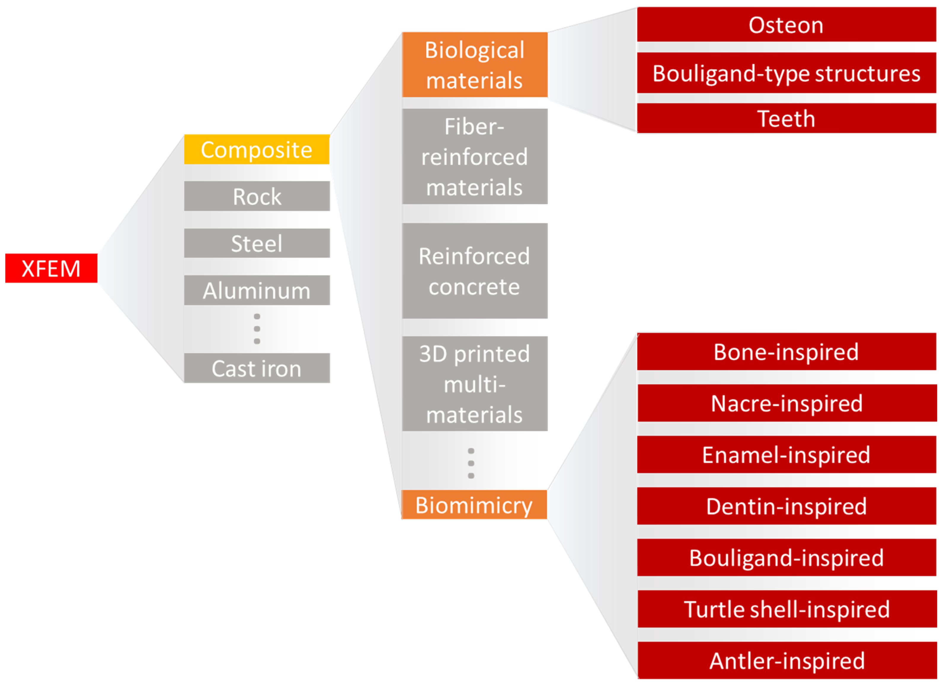
3. XFEM and Porous Materials

Porous materials are widely observed in natural materials and engineering due to their desirable properties that emerge from their porosities, such as large specific surface area [62][63], energy absorption [64], and heat insulation [65]. Porosity and bulk material properties directly affect fracture behavior and the overall behavior of porous materials. Singh et al. [66] modeled a functionally graded plate with a linear variation in material and mechanical properties and studied the failure mode under shear loading. The plate-assigned materials varied from hydroxyapatite to titanium, a condition often seen in fabricated bioimplants. The results highlighted that for both the non-porous and the porous conditions, the crack path tended toward the titanium region. However, in the porous plate, the crack path took a slightly longer path.

4. XFEM and Biological Materials

Nature-made materials have incredible properties such as color shifting [67], self-cleaning [68][69], tissue regeneration [70], and the capacity to resist fracture [71][72]. Significant findings in the fracture behavior of biological materials have also been recently in the spotlight. For instance, the mantis shrimp strikes its prey by releasing an extreme amount of energy from its saddle [73]. Its club-like appendage, known as the dactyl club, is responsible for direct contact with the prey. It is heavily mineralized with specific microstructural architecture to dissipate energy, reducing possible self-inflicted damage [74][75]. Spiders can attach to a variety of surfaces due to their dual attachment system. For smooth surfaces, small hairs located on the tip of their tarsus facilitate organism adhesion through van der Waals forces. Nevertheless, for rougher surfaces, these adhesion forces are not strong enough, and the animal uses its claws to increase the friction with the surface. The claw is made of a hierarchical material with metal ion inclusions, creating a high wear-resistance structure [76]. Mammal bones, in particular, the cortical bone tissue, are load-bearing structures that consist—at the microscale—mostly of osteons, a cylindrical structure with a concentric inner channel surrounded by weaker outer layers called cement lines. Due to its architecture, fracture toughness mechanisms such as crack deflection and arrest occur, increasing considerably the overall fracture toughness of the bone tissue [77][78][79][80]. The influence of the microstructure found in biological tissues on the properties of the macroscale material is evident. However, understanding the mechanisms behind the enhancement in mechanical properties is not trivial, and a combination of experimental and computational analysis is often needed. In this direction, a broad XFEM study evaluated six contrasting biological structures against bending loads [81]. The selected designs are commonly found on nature-made materials: layered (e.g., insect exoskeletons and nacre shells), columnar (e.g., spider silk and tendons), tubular (e.g., dentin and horns), helical (e.g., mantis shrimp dactyl club), sutured (e.g., turtle shells), and sandwich (e.g., toucan beaks). Despite considering simplified designs made by only two components, i.e., soft and stiff building blocks, and other needed simplifications, this study was able to well predict every design fracture behavior. Moreover, it demonstrated the influence of the arrangement of soft–stiff components in biological materials on the mechanical properties. For example, the authors showed that the helical arrangement of columns deflects cracks in the material’s soft matrix structure. This study not only highlighted the XFEM’s performance on composites with complex designs but also provided inspiration to the design of bioinspired materials.
The XFEM applied to the study of cortical bone has been essential to demonstrate that local material heterogeneity is the backbone of the crack propagation path [80][82][83][84]. Li et al. [82] showed that the cement line, i.e., the sheath around the osteon, contributes to deflecting and arrest more cracks when its elastic modulus is 25% lower than that of the osteon. This behavior directly increases the fracture toughness of the material. Gustafsson et al. [83] not only reaffirmed this result but also demonstrated that decreasing the interface strength of the cement line also contributes to an increase in the frequency of crack deflection.
Modeling a composite inner structure is essential to simulate its fracture. However, most of the studies tend to simplify the bone microstructure to facilitate its computational analysis. For example, only one perfectly circular osteon is generally modeled. In a different path, Gustafsson et al. [84] applied X-ray microtomography to extract the bone local tissue orientation maps which were used as input to an XFEM analysis. The innovative method showed very realistic crack paths when compared to the experimental counterparts [85].
As described until now, the most studied type of crack in an osteon is in the transversal direction where the path propagates toward or around the osteonic structure. Nevertheless, microporous damage, localized inside the osteonic region, can also cause complications. Knowing that these regions can have multiple configurations, Yin et al. [86] simulated three kinds of varying shapes (i.e., circular or elliptical) and different orientations. External conditions were set as constant pressure from the interstitial matrix and the Haversian canal. By changing the pressure from 8 MPa to 14 MPa, the study demonstrated that elliptic osteons can modify the crack path and minimize its impact on material failure. For example, it can make the crack propagate along the annular direction rather than toward the Haversian canal.
Single-twisted Bouligand structures are described as helicoidal arrangements oriented across the thickness of the material. This arrangement can be observed in a variety of biological materials such as in the mantis shrimp dactyl club and the locust exoskeleton. This particular structure can create a nest of multiple twisting microcracks, locally releasing energy upon external stresses, and a macroscopic failure [87]. The scales of the coelacanth fish (Latimeria chalumnae) go beyond: their inner structures have overlapping helicoidal configurations, creating a double-twisted Bouligand structure and enhancing the fish defense capability [88].
The XFEM has also been demonstrated as a useful tool in applied dentistry. Perhaps the first publication in the field, Barani et al. [89] applied the XFEM to study the influence of axial forces acting during cracking of the tooth enamel. Despite being a pioneer, the authors still had to pre-set the crack location and size. Further, the same group revisited the method. First, they demonstrated that elongated teeth have higher resistance to longitudinal fracture [90]. Then, Barani et al. [91] evidenced that teeth with graded elastic moduli can increase crack segmentation. Finally, they simulated the splitting of molar teeth using the 3D XFEM, concluding that dentin toughness is more important than strength to fracture evolution [92]. Deep and proximal cracks in the radicular parts of the teeth can either originate from the crown or the root. Nevertheless, they require intervention to preserve the teeth and to avoid unnecessary extraction [93]. One preservation method is the usage of a composite resin core, with materials with a similar elastic modulus to the teeth dentin to minimize local stress concentration. Boonrawd et al. [94] used the XFEM to display the influence of the resin core on altering possible crack initiation and propagation direction. Zhang et al. [95] explored the fracture resistance of a molar tooth with carious lesions and what is the best restoration method. With the aid of 3D XFEM simulations, the authors were able to compare conservative to more invasive restoration methods, highlighting that conservative methods involve less material removal, thus maintaining the tooth fracture resistance. In the same field, Zhang et al. [96] showed, through XFEM 3D modeling, how a crack propagates within a natural tooth upon growing bite forces.

5. XFEM and Bioinspired Materials

Humans are surrounded by biological materials that have established highly optimized functions after a billion-year-long evolution. Bioinspiration refers to extracting knowledge from nature-made systems, materials, or elements to create man-made ideas inspired by them. During the last few decades, encounters with bioinspired elements have been more present in daily life, from aerodynamical train designs based on the beak of a bird [97], to more efficient building ventilation inspired by termite mounds [98] and robot movements that mimic human demonstrations [99]. In the field of structural materials, where new bioinspired materials are daily developed, the material fracture behavior is essential to understanding its deformation and yielding mechanics [100][101]. In this sense, the XFEM is an important computational tool to predict the mechanical properties of bioinspired structures.
Vellwock et al. [102] and Libonati et al. [103] investigated these composite designs with the aid of the XFEM. The computational model of the initial composite design demonstrated great agreement with the experimental results obtained through tensile and three-point bending tests. During the tensile test simulation, the initiated crack was deviated and arrested after contact with the cement-like structure. In the three-point bending, the crack propagated in-between two osteonic regions, following an equal path seen during experimental tests. Moreover, the XFEM reinforced the role of the osteon-like region in delocalizing stresses. The second study focused on the fracture behavior of the composite with additional interlayered glass fibers under external bending stresses, where the crack started in the expected region, on the lower surface of the composite. Then, it grew upwards, partially deviated by an osteon-inspired region. Following this, the crack was arrested and completely deflected by another osteonic structure. The XFEM analysis not only reproduced the experimental condition [103] but also highlighted fracture toughening mechanisms that can be translated to other materials designs.
Recently, Aguilar Coello et al. [104] demonstrated the influence of mineral bridges in a nacre-inspired structure, where the matrix was modeled as a soft hyperelastic material and the filler as a stiff linear elastic material. Despite the usage of non-linear material properties, the authors highlighted the influence of the biomimetic mineral volumetric fraction on the overall fracture behavior, with the aid of the XFEM to simulate single and multi-materials. However, the study evidenced that crack propagation was less problematic on single material specimens. The study was possibly the pioneer in applying the XFEM to simulate complex designs with hyperelastic components.

References

  1. Williams, M.L. The Stresses around a Fault or Crack in Dissimilar Media. Bull. Seismol. Soc. Am. 1959, 49, 199–204.
  2. Rice, J.R.; Sih, G.C. Plane Problems of Cracks in Dissimilar Media. J. Appl. Mech. 1965, 32, 418–423.
  3. Erdogan, F. Stress Distribution in a Nonhomogeneous Elastic Plane with Cracks. J. Appl. Mech. 1963, 30, 232–236.
  4. Cherepanov, G.P. Crack Propagation in Continuous Media: PMM Vol. 31, No. 3, 1967, pp. 476–488. J. Appl. Math. Mech. 1967, 31, 503–512.
  5. Bassani, J.L.; McClintock, F.A. Creep Relaxation of Stress around a Crack Tip. Int. J. Solids Struct. 1981, 17, 479–492.
  6. Irwin, G.R. Fracture. In Elasticity and Plasticity/Elastizität und Plastizität; Flügge, S., Ed.; Handbuch der Physik/Encyclopedia of Physics; Springer: Berlin/Heidelberg, Germany, 1958; pp. 551–590. ISBN 978-3-642-45887-3.
  7. Gajdoš, Ľ.; Šperl, M.; Bayer, J.; Kuželka, J. Comparison of J Integral Assessments for Cracked Plates and Pipes. Materials 2021, 14, 4324.
  8. Rybicki, E.F.; Kanninen, M.F. A Finite Element Calculation of Stress Intensity Factors by a Modified Crack Closure Integral. Eng. Fract. Mech. 1977, 9, 931–938.
  9. Mendonca, W.R.P.; Rodrigues, M.R.B. Application of the Virtual Crack Closure Technique for Cracks in Built-Up Panels. In Proceedings of the 33rd Congress of the International Council of the Aeronautical Science (ICAS), Stockholm, Sweden, 4–9 September 2022.
  10. Barenblatt, G.I. The Formation of Equilibrium Cracks during Brittle Fracture. General Ideas and Hypotheses. Axially-Symmetric Cracks. J. Appl. Math. Mech. 1959, 23, 622–636.
  11. Elliott, H.A. An Analysis of the Conditions for Rupture Due to Griffith Cracks. Proc. Phys. Soc. 1947, 59, 208.
  12. Dugdale, D.S. Yielding of Steel Sheets Containing Slits. J. Mech. Phys. Solids 1960, 8, 100–104.
  13. Sepasdar, R.; Shakiba, M. Overcoming the Convergence Difficulty of Cohesive Zone Models through a Newton-Raphson Modification Technique. Eng. Fract. Mech. 2020, 233, 107046.
  14. Park, K.; Paulino, G.H. Cohesive Zone Models: A Critical Review of Traction-Separation Relationships Across Fracture Surfaces. Appl. Mech. Rev. 2013, 64, 60802.
  15. Zhi, J.; Zhao, L.; Zhang, J.; Liu, Z. A Numerical Method for Simulating the Microscopic Damage Evolution in Composites Under Uniaxial Transverse Tension. Appl. Compos. Mater. 2016, 23, 255–269.
  16. Gentieu, T.; Catapano, A.; Jumel, J.; Broughton, J. A Mean-Field Homogenisation Scheme with CZM-Based Interfaces Describing Progressive Inclusions Debonding. Compos. Struct. 2019, 229, 111398.
  17. Bourdin, B.; Francfort, G.A.; Marigo, J.-J. The Variational Approach to Fracture. J. Elast. 2008, 91, 5–148.
  18. Miehe, C.; Welschinger, F.; Hofacker, M. Thermodynamically Consistent Phase-Field Models of Fracture: Variational Principles and Multi-Field FE Implementations. Int. J. Numer. Methods Eng. 2010, 83, 1273–1311.
  19. Wang, T.; Han, H.; Wang, Y.; Ye, X.; Huang, G.; Liu, Z.; Zhuang, Z. Simulation of Crack Patterns in Quasi-Brittle Materials under Thermal Shock Using Phase Field and Cohesive Zone Models. Eng. Fract. Mech. 2022, 276, 108889.
  20. Zhou, S.; Zhuang, X.; Zhu, H.; Rabczuk, T. Phase Field Modelling of Crack Propagation, Branching and Coalescence in Rocks. Theor. Appl. Fract. Mech. 2018, 96, 174–192.
  21. Xu, W.; Yu, H.; Zhang, J.; Lyu, C.; Wang, Q.; Micheal, M.; Wu, H. Phase-Field Method of Crack Branching during SC-CO2 Fracturing: A New Energy Release Rate Criterion Coupling Pore Pressure Gradient. Comput. Methods Appl. Mech. Eng. 2022, 399, 115366.
  22. Geelen, R.J.M.; Liu, Y.; Hu, T.; Tupek, M.R.; Dolbow, J.E. A Phase-Field Formulation for Dynamic Cohesive Fracture. Comput. Methods Appl. Mech. Eng. 2019, 348, 680–711.
  23. Tanné, E.; Li, T.; Bourdin, B.; Marigo, J.-J.; Maurini, C. Crack Nucleation in Variational Phase-Field Models of Brittle Fracture. J. Mech. Phys. Solids 2018, 110, 80–99.
  24. Navidtehrani, Y.; Betegón, C.; Martínez-Pañeda, E. A Simple and Robust Abaqus Implementation of the Phase Field Fracture Method. Appl. Eng. Sci. 2021, 6, 100050.
  25. Navidtehrani, Y.; Betegón, C.; Martínez-Pañeda, E. A Unified Abaqus Implementation of the Phase Field Fracture Method Using Only a User Material Subroutine. Materials 2021, 14, 1913.
  26. Belytschko, T.; Black, T. Elastic Crack Growth in Finite Elements with Minimal Remeshing. Int. J. Numer. Methods Eng. 1999, 45, 601–620.
  27. Hansbo, A.; Hansbo, P. A Finite Element Method for the Simulation of Strong and Weak Discontinuities in Solid Mechanics. Comput. Methods Appl. Mech. Eng. 2004, 193, 3523–3540.
  28. Song, J.-H.; Areias, P.M.A.; Belytschko, T. A Method for Dynamic Crack and Shear Band Propagation with Phantom Nodes. Int. J. Numer. Methods Eng. 2006, 67, 868–893.
  29. Remmers, J.J.C.; de Borst, R.; Needleman, A. The Simulation of Dynamic Crack Propagation Using the Cohesive Segments Method. J. Mech. Phys. Solids 2008, 56, 70–92.
  30. Salimzadeh, S.; Khalili, N. An XFEM Model for Hydraulic Fracturing in Partially Saturated Rocks. E3S Web Conf. 2016, 9, 08014.
  31. Sivakumar, G.; Maji, V.B. Simulation of Crack Propagation in Rocks by XFEM; Atlantis Press: Amsterdam, The Netherlands, 2016; pp. 291–296.
  32. Wang, T.; Liu, Z.; Zeng, Q.; Gao, Y.; Zhuang, Z. XFEM Modeling of Hydraulic Fracture in Porous Rocks with Natural Fractures. Sci. China Phys. Mech. Astron. 2017, 60, 084612.
  33. Maulianda, B.; Savitri, C.D.; Prakasan, A.; Atdayev, E.; Yan, T.W.; Yong, Y.K.; Elrais, K.A.; Barati, R. Recent Comprehensive Review for Extended Finite Element Method (XFEM) Based on Hydraulic Fracturing Models for Unconventional Hydrocarbon Reservoirs. J. Pet. Explor. Prod. Technol. 2020, 10, 3319–3331.
  34. Cao, B.; Cheng, S.; Li, A.; Deng, Y.; Fang, Z. Fatigue Crack Propagation Study of Bridge Steel Q345qD Based on XFEM Considering the Influence of the Stress Ratio. Appl. Sci. 2022, 12, 12782.
  35. Oulad Brahim, A.; Belaidi, I.; Fahem, N.; Khatir, S.; Mirjalili, S.; Abdel Wahab, M. Prediction of the Peak Load and Crack Initiation Energy of Dynamic Brittle Fracture in X70 Steel Pipes Using an Improved Artificial Neural Network and Extended Finite Element Method. Theor. Appl. Fract. Mech. 2022, 122, 103627.
  36. Mirmohammad, S.H.; Safarabadi, M.; Karimpour, M.; Aliha, M.R.M.; Berto, F. Study of Composite Fiber Reinforcement of Cracked Thin-Walled Pressure Vessels Utilizing Multi-Scaling Technique Based on Extended Finite Element Method. Strength Mater. 2018, 50, 925–936.
  37. Valadi, Z.; Bayesteh, H.; Mohammadi, S. XFEM Fracture Analysis of Cracked Pipeline with and without FRP Composite Repairs. Mech. Adv. Mater. Struct. 2020, 27, 1888–1899.
  38. Prodromou, M.; Dow, R.S. Flexural Response of Composite Coated Steel Components Using the Extended Finite Element Method. Mar. Struct. 2022, 85, 103266.
  39. Chang, Y.; Song, Q.; Kuang, Z.; Zhang, K.; Zheng, Z. Fracture Analysis of Cast Iron Materials with Cracks Based on Elastoplastic Extended Finite Element Method. Acta Mech. Solida Sin. 2019, 32, 201–214.
  40. Tsuda, T.; Ohnishi, Y.; Ohtagaki, R.; Cho, K.; Fujimoto, T. Three-Point Bending Crack Propagation Analysis of Beam Subjected to Eccentric Impact Loading by X-FEM. In Proceedings of the 10th European LS-DYNA Conference, Würzburg, Germany, 15–17 June 2015.
  41. Gairola, S.; Jayaganthan, R. XFEM Simulation of Tensile and Fracture Behavior of Ultrafine-Grained Al 6061 Alloy. Metals 2021, 11, 1761.
  42. Suman, S.; Dwivedi, K.; Anand, S.; Pathak, H. XFEM–ANN Approach to Predict the Fatigue Performance of a Composite Patch Repaired Aluminium Panel. Compos. Part C Open Access 2022, 9, 100326.
  43. Xie, X.; Feng, Q.; Zhang, M.; Liao, N. Evaluating Fracture Properties and Interfacial Strengths of Silicon Oxycarbide Thin-Films: XFEM Simulations and Experimental Validation. Eng. Fract. Mech. 2023, 292, 109648.
  44. Deng, J.; Liao, N.; Zhou, H.; Xue, W. Predicting Plastic and Fracture Properties of Silicon Oxycarbide Thin Films Using Extended Finite Element Method. J. Alloys Compd. 2019, 792, 481–486.
  45. Swati, R.F.; Wen, L.H.; Elahi, H.; Khan, A.A.; Shad, S. Extended Finite Element Method (XFEM) Analysis of Fiber Reinforced Composites for Prediction of Micro-Crack Propagation and Delaminations in Progressive Damage: A Review. Microsyst. Technol. 2019, 25, 747–763.
  46. Fascetti, A.; Feo, L.; Abbaszadeh, H. A Critical Review of Numerical Methods for the Simulation of Pultruded Fiber-Reinforced Structural Elements. Compos. Struct. 2021, 273, 114284.
  47. Gao, X.; Umair, M.; Nawab, Y.; Latif, Z.; Ahmad, S.; Siddique, A.; Yang, H. Mode I Fatigue of Fibre Reinforced Polymeric Composites: A Review. Polymers 2022, 14, 4558.
  48. Kim, D.-H.; Park, M.J.; Chang, Y.-S.; Baek, U.B. Evaluation of Fracture Properties of Two Metallic Materials under Hydrogen Gas Conditions by Using XFEM. Metals 2022, 12, 1813.
  49. Condit, C.W. The First Reinforced-Concrete Skyscraper: The Ingalls Building in Cincinnati and Its Place in Structural History. Technol. Cult. 1968, 9, 1–33.
  50. Chen, H.; Xu, B.; Wang, J.; Nie, X.; Mo, Y.-L. XFEM-Based Multiscale Simulation on Monotonic and Hysteretic Behavior of Reinforced-Concrete Columns. Appl. Sci. 2020, 10, 7899.
  51. Yu, J.; Zhan, K.; Li, L.; Yu, K. Using XFEM to Model the Effect of Different Axial Compression on the Hysteretic Behaviour of the Flexure-Dominant RC Columns. Struct. Des. Tall Spec. Build. 2018, 27, e1465.
  52. Chung, C.-H.; Kim, D.-H.; Park, J. Diagonal Crack Propagation Analysis of Reinforced Concrete Beams Using XFEM; Itsan: Seoul, Republic of Korea, 2017.
  53. Marzec, I.; Bobiński, J. Quantitative Assessment of the Influence of Tensile Softening of Concrete in Beams under Bending by Numerical Simulations with XFEM and Cohesive Cracks. Materials 2022, 15, 626.
  54. Pike, M.G.; Oskay, C. Modeling Random Short Nanofiber- and Microfiber-Reinforced Composites Using the Extended Finite-Element Method. J. Nanomechan. Micromechan. 2015, 5, A4014005.
  55. Pike, M.G.; Oskay, C. Three-Dimensional Modeling of Short Fiber-Reinforced Composites with Extended Finite-Element Method. J. Eng. Mech. 2016, 142, 04016087.
  56. Serna Moreno, M.C.; Curiel-Sosa, J.L.; Navarro-Zafra, J.; Martínez Vicente, J.L.; López Cela, J.J. Crack Propagation in a Chopped Glass-Reinforced Composite under Biaxial Testing by Means of XFEM. Compos. Struct. 2015, 119, 264–271.
  57. Infante-García, D.; Qian, G.; Miguélez, H.; Giner, E. Analysis of the Effect of Out-of-Phase Biaxial Fatigue Loads on Crack Paths in Cruciform Specimens Using XFEM. Int. J. Fatigue 2019, 123, 87–95.
  58. Nasirmanesh, A.; Mohammadi, S. XFEM Buckling Analysis of Cracked Composite Plates. Compos. Struct. 2015, 131, 333–343.
  59. Safri, S.N.A.B.; Sultan, M.T.H.; Jawaid, M. Damage Analysis of Glass Fiber Reinforced Composites. In Durability and Life Prediction in Biocomposites, Fibre-Reinforced Composites and Hybrid Composites; Jawaid, M., Thariq, M., Saba, N., Eds.; Woodhead Publishing Series in Composites Science and Engineering; Woodhead Publishing: Sawston, UK, 2019; pp. 133–147. ISBN 978-0-08-102290-0.
  60. Abdullah, N.A.; Curiel-Sosa, J.L.; Taylor, Z.A.; Tafazzolimoghaddam, B.; Martinez Vicente, J.L.; Zhang, C. Transversal Crack and Delamination of Laminates Using XFEM. Compos. Struct. 2017, 173, 78–85.
  61. Curiel Sosa, J.L.; Karapurath, N. Delamination Modelling of GLARE Using the Extended Finite Element Method. Compos. Sci. Technol. 2012, 72, 788–791.
  62. Recio-Sánchez, G.; Torres-Costa, V.; Manso, M.; Gallach, D.; López-García, J.; Martín-Palma, R.J. Towards the Development of Electrical Biosensors Based on Nanostructured Porous Silicon. Materials 2010, 3, 755–763.
  63. Granitzer, P.; Rumpf, K. Porous Silicon—A Versatile Host Material. Materials 2010, 3, 943–998.
  64. Wang, J.; Liu, A.; Ao, Q.; Wu, C.; Ma, J.; Cao, P. Energy Absorption Characteristics and Preparation of Porous Titanium with High Porosity. Mater. Today Commun. 2023, 34, 105003.
  65. Ruckdeschel, P.; Philipp, A.; Retsch, M. Understanding Thermal Insulation in Porous, Particulate Materials. Adv. Funct. Mater. 2017, 27, 1702256.
  66. Prashant Singh, A.; Tailor, A.; Singh Tumrate, C.; Mishra, D. Crack Growth Simulation in a Functionally Graded Material Plate with Uniformly Distributed Pores Using Extended Finite Element Method. Mater. Today Proc. 2022, 60, 602–607.
  67. Wang, Y.; Cui, H.; Zhao, Q.; Du, X. Chameleon-Inspired Structural-Color Actuators. Matter 2019, 1, 626–638.
  68. Vellwock, A.E.; Su, P.; Zhang, Z.; Feng, D.; Yao, H. Reconciling the Conflict between Optical Transparency and Fouling Resistance with a Nanowrinkled Surface Inspired by Zebrafish’s Cornea. ACS Appl. Mater. Interfaces 2022, 14, 7617–7625.
  69. Vellwock, A.E.; Yao, H. Biomimetic and Bioinspired Surface Topographies as a Green Strategy for Combating Biofouling: A Review. Bioinspir. Biomim. 2021, 16, 041003.
  70. Marques, I.J.; Lupi, E.; Mercader, N. Model Systems for Regeneration: Zebrafish. Development 2019, 146, dev167692.
  71. Pro, J.W.; Barthelat, F. The Fracture Mechanics of Biological and Bioinspired Materials. MRS Bull. 2019, 44, 46–52.
  72. Yao, H.; Xie, Z.; He, C.; Dao, M. Fracture Mode Control: A Bio-Inspired Strategy to Combat Catastrophic Damage. Sci. Rep. 2015, 5, 8011.
  73. Tadayon, M.; Amini, S.; Masic, A.; Miserez, A. The Mantis Shrimp Saddle: A Biological Spring Combining Stiffness and Flexibility. Adv. Funct. Mater. 2015, 25, 6437–6447.
  74. Behera, R.P.; Le Ferrand, H. Impact-Resistant Materials Inspired by the Mantis Shrimp’s Dactyl Club. Matter 2021, 4, 2831–2849.
  75. Amini, S.; Tadayon, M.; Loke, J.J.; Kumar, A.; Kanagavel, D.; Le Ferrand, H.; Duchamp, M.; Raida, M.; Sobota, R.M.; Chen, L.; et al. A Diecast Mineralization Process Forms the Tough Mantis Shrimp Dactyl Club. Proc. Natl. Acad. Sci. USA 2019, 116, 8685–8692.
  76. Tadayon, M.; Younes-Metzler, O.; Shelef, Y.; Zaslansky, P.; Rechels, A.; Berner, A.; Zolotoyabko, E.; Barth, F.G.; Fratzl, P.; Bar-On, B.; et al. Adaptations for Wear Resistance and Damage Resilience: Micromechanics of Spider Cuticular “Tools”. Adv. Funct. Mater. 2020, 30, 2000400.
  77. Libonati, F.; Vergani, L. Understanding the Structure–Property Relationship in Cortical Bone to Design a Biomimetic Composite. Compos. Struct. 2016, 139, 188–198.
  78. Vergani, L.; Colombo, C.; Libonati, F. Crack Propagation in Cortical Bone: A Numerical Study. Procedia Mater. Sci. 2014, 3, 1524–1529.
  79. Casari, D.; Michler, J.; Zysset, P.; Schwiedrzik, J. Microtensile Properties and Failure Mechanisms of Cortical Bone at the Lamellar Level. Acta Biomater. 2021, 120, 135–145.
  80. Gustafsson, A.; Khayyeri, H.; Wallin, M.; Isaksson, H. An Interface Damage Model That Captures Crack Propagation at the Microscale in Cortical Bone Using XFEM. J. Mech. Behav. Biomed. Mater. 2019, 90, 556–565.
  81. Chen, G.; Lin, T.; Guo, C.; Richter, L.; Dai, N. Bending Study of Six Biological Models for Design of High Strength and Tough Structures. Biomimetics 2022, 7, 176.
  82. Li, S.; Abdel-Wahab, A.; Demirci, E.; Silberschmidt, V.V. Fracture Process in Cortical Bone: X-FEM Analysis of Microstructured Models. Int. J. Fract. 2013, 184, 43–55.
  83. Gustafsson, A.; Wallin, M.; Khayyeri, H.; Isaksson, H. Crack Propagation in Cortical Bone Is Affected by the Characteristics of the Cement Line: A Parameter Study Using an XFEM Interface Damage Model. Biomech. Model. Mechanobiol. 2019, 18, 1247–1261.
  84. Gustafsson, A.; Wallin, M.; Isaksson, H. The Influence of Microstructure on Crack Propagation in Cortical Bone at the Mesoscale. J. Biomech. 2020, 112, 110020.
  85. Gustafsson, A.; Mathavan, N.; Turunen, M.J.; Engqvist, J.; Khayyeri, H.; Hall, S.A.; Isaksson, H. Linking Multiscale Deformation to Microstructure in Cortical Bone Using in Situ Loading, Digital Image Correlation and Synchrotron X-Ray Scattering. Acta Biomater. 2018, 69, 323–331.
  86. Yin, D.; Chen, B.; Lin, S. Finite Element Analysis on Multi-Toughening Mechanism of Microstructure of Osteon. J. Mech. Behav. Biomed. Mater. 2021, 117, 104408.
  87. Suksangpanya, N.; Yaraghi, N.A.; Kisailus, D.; Zavattieri, P. Twisting Cracks in Bouligand Structures. Struct.-Prop. Relatsh. Biol. Bioinspired Mater. 2017, 76, 38–57.
  88. Sherman, V.R.; Quan, H.; Yang, W.; Ritchie, R.O.; Meyers, M.A. A Comparative Study of Piscine Defense: The Scales of Arapaima Gigas, Latimeria Chalumnae and Atractosteus Spatula. Biol. Articul. Struct. Prot. Des. 2017, 73, 1–16.
  89. Barani, A.; Keown, A.J.; Bush, M.B.; Lee, J.J.-W.; Chai, H.; Lawn, B.R. Mechanics of Longitudinal Cracks in Tooth Enamel. Acta Biomater. 2011, 7, 2285–2292.
  90. Barani, A.; Keown, A.J.; Bush, M.B.; Lee, J.J.-W.; Lawn, B.R. Role of Tooth Elongation in Promoting Fracture Resistance. J. Mech. Behav. Biomed. Mater. 2012, 8, 37–46.
  91. Barani, A.; Bush, M.B.; Lawn, B.R. Effect of Property Gradients on Enamel Fracture in Human Molar Teeth. J. Mech. Behav. Biomed. Mater. 2012, 15, 121–130.
  92. Barani, A.; Chai, H.; Lawn, B.R.; Bush, M.B. Mechanics Analysis of Molar Tooth Splitting. Acta Biomater. 2015, 15, 237–243.
  93. Malentacca, A.; Zaccheo, F.; Scialanca, M.; Fordellone, F.; Rupe, C.; Lajolo, C. Repair of Teeth with Cracks in Crowns and Roots: An Observational Clinical Study. Int. Endod. J. 2021, 54, 1738–1753.
  94. Boonrawd, N.; Rungsiyakull, P.; Rungsiyakull, C.; Louwakul, P. Effects of Composite Resin Core Level and Periodontal Pocket Depth on Crack Propagation in Endodontically Treated Teeth: An Extended Finite Element Method Study. J. Prosthet. Dent. 2022, 128, 195.e1–195.e7.
  95. Zhang, Z.; Zheng, K.; Li, E.; Li, W.; Li, Q.; Swain, M.V. Mechanical Benefits of Conservative Restoration for Dental Fissure Caries. J. Mech. Behav. Biomed. Mater. 2016, 53, 11–20.
  96. Zhang, Y.; Liu, Y.; She, Y.; Liang, Y.; Xu, F.; Fang, C. The Effect of Endodontic Access Cavities on Fracture Resistance of First Maxillary Molar Using the Extended Finite Element Method. J. Endod. 2019, 45, 316–321.
  97. Chaturvedi, I.; Jandyal, A.; Wazir, I.; Raina, A.; Ul Haq, M.I. Biomimetics and 3D Printing—Opportunities for Design Applications. Sens. Int. 2022, 3, 100191.
  98. Paar, M.J.; Petutschnigg, A. Biomimetic Inspired, Natural Ventilated Façade—A Conceptual Study. J. Facade Des. Eng. 2016, 4, 131–142.
  99. Zahra, O.; Tolu, S.; Zhou, P.; Duan, A.; Navarro-Alarcon, D. A Bio-Inspired Mechanism for Learning Robot Motion From Mirrored Human Demonstrations. Front. Neurorobot. 2022, 16, 826410.
  100. Libonati, F.; Buehler, M.J. Advanced Structural Materials by Bioinspiration. Adv. Eng. Mater. 2017, 19, 1600787.
  101. Buccino, F.; Aiazzi, I.; Casto, A.; Liu, B.; Sbarra, M.C.; Ziarelli, G.; Vergani, L.M.; Bagherifard, S. Down to the Bone: A Novel Bio-Inspired Design Concept. Materials 2021, 14, 4226.
  102. Vellwock, A.E.; Vergani, L.; Libonati, F. A Multiscale XFEM Approach to Investigate the Fracture Behavior of Bio-Inspired Composite Materials. Compos. Part B Eng. 2018, 141, 258–264.
  103. Libonati, F.; Vellwock, A.E.; Ielmini, F.; Abliz, D.; Ziegmann, G.; Vergani, L. Bone-Inspired Enhanced Fracture Toughness of de Novo Fiber Reinforced Composites. Sci. Rep. 2019, 9, 3142.
  104. Aguilar Coello, A.E.; Vellwock, A.E.; Avanzini, A.; Libonati, F. Unfolding the Role of Topology-Driven Toughening Mechanisms in Nacre-like Composite Design through XFEM. Compos. Struct. 2023, 321, 117285.
More
Information
Subjects: Mechanics
Contributors MDPI registered users' name will be linked to their SciProfiles pages. To register with us, please refer to https://encyclopedia.pub/register : ,
View Times: 71
Revisions: 2 times (View History)
Update Date: 08 Feb 2024
1000/1000