The finite element method (FEM) has revolutionized material design by reducing redesign time and costs through prefabrication and structural optimization. The FEM facilitates the assessment of mechanical properties, such as the maximum load a bridge can withstand and where the failure point might be, and the number of cycles an automobile suspension can last before discontinuity. Understanding the fracture behavior (e.g., crack nucleation and propagation) is essential. Yet, the standard FEM cannot fully model fracture. In the last few decades, a few methods have emerged to cover this gap. Perhaps the first, after observation of stress around cracks
[1], the contour integral method (CIM) and its variations have been proposed to calculate the stress intensity factor on cracked media
[2][3][2,3]. Embedded on commercial software, and directly related to CIM, J-integral
[4], C
T-integral
[5], and T-stress
[6] are available. Despite clear advantages such as robustness, calculation speed, and simplicity, the CIM requires the modeling of the crack plane or line, specification of its front
[7], and careful mesh preparation. Moreover, it gives only a step-wise output as it does not simulate the propagation path. The virtual crack closing technique (VCCT), developed in 1977
[8], calculates the energy release rate and propagation mode of a pre-defined crack. Besides, it can simulate the crack path on commercial software, an improvement from the CIM. However, the VCCT is a numerically challenging method and can only simulate brittle fracturing
[9]. Thus, it is commonly employed on simpler models such as for delamination and debonding case studies. The cohesive zone element (CZM)
[10][11][12][10,11,12] applies cohesive regions to understand non-linear behavior on the front of a pre-defined crack. The CZM also requires that the crack propagation path be pre-set. Despite moderate numerical convergence
[13], these requirements limit its applicability to crack modeling. In this sense, the CZM, like the VCCT, is mainly utilized for debonding analyses
[14][15][16][14,15,16]. The phase-field model (PFM) was introduced in 2008
[17], quickly followed by another publication in 2010
[18]. The PFM is surpassing the CIM, VCCT, and CZM because it employs a scalar field (i.e., the phase field) to smoothly transition from the intact to the damaged element and does not consider the crack as a physical discontinuity
[19][20][19,20]. In addition, the PFM can model multiple cracks and their branching and merging
[21]. However, issues such as diffuse damage profile due to regularization length are often encountered
[22][23][22,23], requiring proper user input to overcome it
[23]. Currently, the PFM’s direct implementation in commercial software is absent and requires user input subroutines
[20][24][25][20,24,25], reducing its popularization among the fracture mechanics community. A summary of the pros and cons of numerical methods that can simulate fracture behavior is available in
Table 1.
2. XFEM and Composites
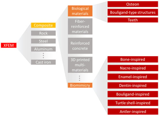
The XFEM has been applied to simulate fracture behavior in a variety of materials (
Figure 1), ranging from rocks
[30][31][32][33][40,41,42,43] to steel
[34][35][36][37][38][44,45,46,47,48], cast iron
[39][40][49,50], aluminum
[41][42][51,52], silicon oxycarbide
[43][44][53,54], and composites
[45][46][47][55,56,57]. In the steel industry, the XFEM has been applied to better understand fatigue crack propagation on bridges
[34][44], the impact properties of high-pressure gas transportation pipes
[35][45], and the flexural response of coated steel used for yacht manufacturing
[38][48]. Considering cast iron, Chang et al.
[39][49] showed that the XFEM results were in great agreement with experimental uniaxial tests, demonstrating the material elastoplastic behavior. Applying a complex loading condition, with an eccentric impact load on a three-point bending cast iron structure, Tsuda et al.
[40][50] highlighted the flexibility of the XFEM in uncommon cases. For an aluminum alloy sample, Gairola and Jayaganthan
[41][51] correctly predicted the material fracture toughness, suggesting that 3D XFEM simulations are slightly better than 2D. Kim et al.
[48][58] showed the effects of hydrogen gas on the fracture behavior of an aluminum alloy by simulating fracture resistance curves of compact tension specimens. The XFEM load and displacement curves were within 5% of the experimental conditions. Recently, Xie et al.
[43][53] captured the mechanical and fracture behavior of a silicon carbide film, where the XFEM was a successful method for evaluating interfacial strength.
Figure 1.
A diagram of XFEM usage in material simulations, highlighting its application to the field of biomaterials and bioinspired materials.
Composites is a growing field that is based on the design of materials with two or more components to create multi-material structures with particular mechanical properties. For example, the construction industry uses reinforced concrete as a load-bearing structure in the development of buildings
[49][59]. Reinforced concrete refers to the use of aligned metallic bars in a concrete mix, where the bars play the essential role of increasing the composite’s overall load-bearing capacity. The modeling of columns made of reinforced concrete showed that the XFEM can predict the start location and growth pattern of cracks when the structure is subjected to monotonic or cyclic loadings
[50][51][60,61]. Chung et al.
[52][62] simulated a bending test of a reinforced concrete beam and demonstrated that the XFEM was able to initiate cracks in the majority of the locations experimentally observed. Moreover, the authors discussed problematics about the method’s convergence which were possibly accentuated by the choice of a 3D model over a simplified 2D. Marzec and Bobiński
[53][63] studied the influence of cohesive softening law on XFEM simulations of concrete beams under bending. The authors applied three softening cases: bilinear, exponential, and a rational Bezier, concluding that all produced consistent results if different fracture energies are considered.
In the composite field, the method has been extensively used to study fiber-reinforced materials, such as in studies that evaluated the influence of random short fiber inclusions in composites, considering 2D
[54][64] and 3D simulations
[55][65]. Pike and Oskay
[54][64] implemented a modified framework to understand the effect of random fiber inclusions, comparing the method to standard finite element modeling in case studies such as single fiber inclusion and random short fiber composites. In another study, Pike and Oskay
[55][65] successfully showed that the influence of short fibers on composite materials can be modeled in a 3D simulation, rather than the previous 2D one. Serna Moreno et al.
[56][66] showed that in bi-axial tensile tests of chopped glass-reinforced composites, the XFEM simulated crack start location, path, and even growth velocity in agreement with the experimental results. XFEM fatigue simulation on similar bi-axial samples demonstrated the capacity of the method to analyze fracture behavior under complex loads
[57][67]. Fracturing is a large issue for composite structures. In thin plates where buckling can easily occur, the issue is also present. Simulations of cracks in composite plates using the XFEM facilitated the analysis of the crack lengths and angles, fiber directions, and even boundary conditions on overall structural behavior during buckling
[58][68].
Delamination is one of the most crucial damages that can occur on impacted composites
[59][69]. It refers to a de-adhesion of adjacent components, such as the peeling of a coating on a substrate and the detachment of fibers in a matrix. Despite a local effect, it can compromise the capacity of a whole structure to withstand loading. Carbon fiber composites and glass fiber-reinforced aluminum laminates are widely applied to the aerospace and high-end automotive industries. In this sense, Abdullah et al.
[60][70] demonstrated that the XFEM is a useful tool to simulate delamination in carbon fiber composites with different fiber orientations, displaying the orientation influence on the crack path. Moreover, the XFEM fracture behavior agreed with the experimental results. Curiel Sosa and Karapurath
[61][71] obtained similar results while simulating delamination in fiber metal laminates. The authors also suggested the XFEM as a computational time-saving tool and reinforced that the method is independent of the finite element size.
3. XFEM and Porous Materials
Porous materials are widely observed in natural materials and engineering due to their desirable properties that emerge from their porosities, such as large specific surface area
[62][63][72,73], energy absorption
[64][74], and heat insulation
[65][75]. Porosity and bulk material properties directly affect fracture behavior and the overall behavior of porous materials. Singh et al.
[66][76] modeled a functionally graded plate with a linear variation in material and mechanical properties and studied the failure mode under shear loading. The plate-assigned materials varied from hydroxyapatite to titanium, a condition often seen in fabricated bioimplants. The results highlighted that for both the non-porous and the porous conditions, the crack path tended toward the titanium region. However, in the porous plate, the crack path took a slightly longer path.
4. XFEM and Biological Materials
Nature-made materials have incredible properties such as color shifting
[67][79], self-cleaning
[68][69][80,81], tissue regeneration
[70][82], and the capacity to resist fracture
[71][72][83,84]. Significant findings in the fracture behavior of biological materials have also been recently in the spotlight. For instance, the mantis shrimp strikes its prey by releasing an extreme amount of energy from its saddle
[73][85]. Its club-like appendage, known as the dactyl club, is responsible for direct contact with the prey. It is heavily mineralized with specific microstructural architecture to dissipate energy, reducing possible self-inflicted damage
[74][75][86,87]. Spiders can attach to a variety of surfaces due to their dual attachment system. For smooth surfaces, small hairs located on the tip of their tarsus facilitate organism adhesion through van der Waals forces. Nevertheless, for rougher surfaces, these adhesion forces are not strong enough, and the animal uses its claws to increase the friction with the surface. The claw is made of a hierarchical material with metal ion inclusions, creating a high wear-resistance structure
[76][88]. Mammal bones, in particular, the cortical bone tissue, are load-bearing structures that consist—at the microscale—mostly of osteons, a cylindrical structure with a concentric inner channel surrounded by weaker outer layers called cement lines. Due to its architecture, fracture toughness mechanisms such as crack deflection and arrest occur, increasing considerably the overall fracture toughness of the bone tissue
[77][78][79][80][89,90,91,92]. The influence of the microstructure found in biological tissues on the properties of the macroscale material is evident. However, understanding the mechanisms behind the enhancement in mechanical properties is not trivial, and a combination of experimental and computational analysis is often needed. In this direction, a broad XFEM study evaluated six contrasting biological structures against bending loads
[81][93]. The selected designs are commonly found on nature-made materials: layered (e.g., insect exoskeletons and nacre shells), columnar (e.g., spider silk and tendons), tubular (e.g., dentin and horns), helical (e.g., mantis shrimp dactyl club), sutured (e.g., turtle shells), and sandwich (e.g., toucan beaks). Despite considering simplified designs made by only two components, i.e., soft and stiff building blocks, and other needed simplifications, this study was able to well predict every design fracture behavior. Moreover, it demonstrated the influence of the arrangement of soft–stiff components in biological materials on the mechanical properties. For example, the authors showed that the helical arrangement of columns deflects cracks in the material’s soft matrix structure. This study not only highlighted the XFEM’s performance on composites with complex designs but also provided inspiration to the design of bioinspired materials.
The XFEM applied to the study of cortical bone has been essential to demonstrate that local material heterogeneity is the backbone of the crack propagation path
[80][82][83][84][92,94,95,96]. Li et al.
[82][94] showed that the cement line, i.e., the sheath around the osteon, contributes to deflecting and arrest more cracks when its elastic modulus is 25% lower than that of the osteon. This behavior directly increases the fracture toughness of the material. Gustafsson et al.
[83][95] not only reaffirmed this result but also demonstrated that decreasing the interface strength of the cement line also contributes to an increase in the frequency of crack deflection.
Modeling a composite inner structure is essential to simulate its fracture. However, most of the studies tend to simplify the bone microstructure to facilitate its computational analysis. For example, only one perfectly circular osteon is generally modeled. In a different path, Gustafsson et al.
[84][96] applied X-ray microtomography to extract the bone local tissue orientation maps which were used as input to an XFEM analysis. The innovative method showed very realistic crack paths when compared to the experimental counterparts
[85][97].
As described until now, the most studied type of crack in an osteon is in the transversal direction where the path propagates toward or around the osteonic structure. Nevertheless, microporous damage, localized inside the osteonic region, can also cause complications. Knowing that these regions can have multiple configurations, Yin et al.
[86][104] simulated three kinds of varying shapes (i.e., circular or elliptical) and different orientations. External conditions were set as constant pressure from the interstitial matrix and the Haversian canal. By changing the pressure from 8 MPa to 14 MPa, the study demonstrated that elliptic osteons can modify the crack path and minimize its impact on material failure. For example, it can make the crack propagate along the annular direction rather than toward the Haversian canal.
Single-twisted Bouligand structures are described as helicoidal arrangements oriented across the thickness of the material. This arrangement can be observed in a variety of biological materials such as in the mantis shrimp dactyl club and the locust exoskeleton. This particular structure can create a nest of multiple twisting microcracks, locally releasing energy upon external stresses, and a macroscopic failure
[87][105]. The scales of the coelacanth fish (
Latimeria chalumnae) go beyond: their inner structures have overlapping helicoidal configurations, creating a double-twisted Bouligand structure and enhancing the fish defense capability
[88][106].
The XFEM has also been demonstrated as a useful tool in applied dentistry. Perhaps the first publication in the field, Barani et al.
[89][108] applied the XFEM to study the influence of axial forces acting during cracking of the tooth enamel. Despite being a pioneer, the authors still had to pre-set the crack location and size. Further, the same group revisited the method. First, they demonstrated that elongated teeth have higher resistance to longitudinal fracture
[90][109]. Then, Barani et al.
[91][110] evidenced that teeth with graded elastic moduli can increase crack segmentation. Finally, they simulated the splitting of molar teeth using the 3D XFEM, concluding that dentin toughness is more important than strength to fracture evolution
[92][111]. Deep and proximal cracks in the radicular parts of the teeth can either originate from the crown or the root. Nevertheless, they require intervention to preserve the teeth and to avoid unnecessary extraction
[93][112]. One preservation method is the usage of a composite resin core, with materials with a similar elastic modulus to the teeth dentin to minimize local stress concentration. Boonrawd et al.
[94][113] used the XFEM to display the influence of the resin core on altering possible crack initiation and propagation direction. Zhang et al.
[95][114] explored the fracture resistance of a molar tooth with carious lesions and what is the best restoration method. With the aid of 3D XFEM simulations, the authors were able to compare conservative to more invasive restoration methods, highlighting that conservative methods involve less material removal, thus maintaining the tooth fracture resistance. In the same field, Zhang et al.
[96][115] showed, through XFEM 3D modeling, how a crack propagates within a natural tooth upon growing bite forces.
5. XFEM and Bioinspired Materials
Humans are surrounded by biological materials that have established highly optimized functions after a billion-year-long evolution. Bioinspiration refers to extracting knowledge from nature-made systems, materials, or elements to create man-made ideas inspired by them. During the last few decades, encounters with bioinspired elements have been more present in daily life, from aerodynamical train designs based on the beak of a bird
[97][116], to more efficient building ventilation inspired by termite mounds
[98][117] and robot movements that mimic human demonstrations
[99][118]. In the field of structural materials, where new bioinspired materials are daily developed, the material fracture behavior is essential to understanding its deformation and yielding mechanics
[100][101][119,120]. In this sense, the XFEM is an important computational tool to predict the mechanical properties of bioinspired structures.
Vellwock et al.
[102][124] and Libonati et al.
[103][123] investigated these composite designs with the aid of the XFEM. The computational model of the initial composite design demonstrated great agreement with the experimental results obtained through tensile and three-point bending tests. During the tensile test simulation, the initiated crack was deviated and arrested after contact with the cement-like structure. In the three-point bending, the crack propagated in-between two osteonic regions, following an equal path seen during experimental tests. Moreover, the XFEM reinforced the role of the osteon-like region in delocalizing stresses. The second study focused on the fracture behavior of the composite with additional interlayered glass fibers under external bending stresses, where the crack started in the expected region, on the lower surface of the composite. Then, it grew upwards, partially deviated by an osteon-inspired region. Following this, the crack was arrested and completely deflected by another osteonic structure. The XFEM analysis not only reproduced the experimental condition
[103][123] but also highlighted fracture toughening mechanisms that can be translated to other materials designs.
Recently, Aguilar Coello et al.
[104][128] demonstrated the influence of mineral bridges in a nacre-inspired structure, where the matrix was modeled as a soft hyperelastic material and the filler as a stiff linear elastic material. Despite the usage of non-linear material properties, the authors highlighted the influence of the biomimetic mineral volumetric fraction on the overall fracture behavior, with the aid of the XFEM to simulate single and multi-materials. However, the study evidenced that crack propagation was less problematic on single material specimens. The study was possibly the pioneer in applying the XFEM to simulate complex designs with hyperelastic components.