 +1 credit
| Version | Summary | Created by | Modification | Content Size | Created at | Operation |
|---|---|---|---|---|---|---|
| 1 | Francisco P. Brito | -- | 7454 | 2024-01-11 16:01:17 | | | |
| 2 | Lindsay Dong | + 47 word(s) | 7501 | 2024-01-12 02:06:55 | | | | |
| 3 | Lindsay Dong | Meta information modification | 7501 | 2024-01-12 02:10:00 | | |
Video Upload Options
The current state of hydrogen as an energy vector is marked by its growing importance and recognition worldwide. Despite its still formidable challenges, once it achieves some maturity, it might be seen as a promising solution to address climate change, reduce emissions, and facilitate the transition towards a sustainable energy future. Collaborative international efforts highlight its significance. While challenges exist and these should not be underestimated, the momentum behind hydrogen suggests that policymakers all around the world see a promising future in the global energy transition towards a cleaner future for both developed and developing countries, and thus for the world.
1. Hydrogen
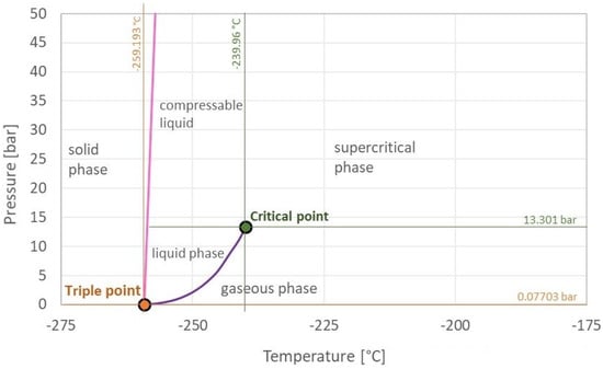
Hydrogen is the most abundant element in the Universe, and it is primarily found on Earth in molecules such as water and organic compounds [1]. It is the first and simplest element in the periodic table, having the smallest atomic mass of 1.008 g/mol and being composed of only one proton and one electron [2][3]. Atomic hydrogen does not exist under normal conditions [3]. In turn, hydrogen is found as a two-atom combination, forming the hydrogen molecule (H2).
2. Green Hydrogen Production Processes
2.1. Introduction
2.2. Hydrogen Production Processes
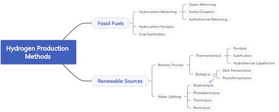
2.2.1. Hydrogen Production from Fossil Fuels
2.2.2. Hydrogen Production from Biomass
2.2.3. Hydrogen Production from Water
2.3. Hydrogen Colour Code
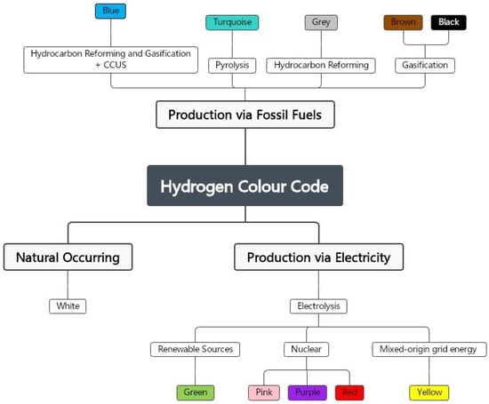
2.3.1. Black and Brown Hydrogen
2.3.2. Grey Hydrogen
2.3.3. Turquoise Hydrogen
2.3.4. Blue Hydrogen
2.3.5. Yellow Hydrogen
2.3.6. Pink, Red, and Purple Hydrogen
2.3.7. White Hydrogen
2.3.8. Green Hydrogen
2.4. Water Electrolysis
-
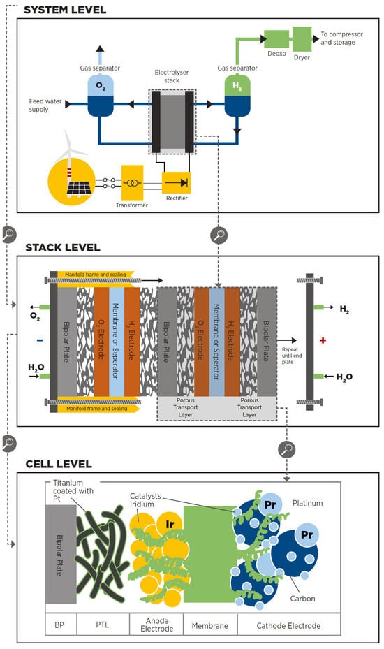
The cell is the electrolyser’s heart and the site of the electrochemical process. Common cells consist of two electrodes—anode and cathode—immersed in a liquid electrolyte or adjacent to a solid electrolyte membrane, two porous transport layers (PTLs) that facilitate reactant transport and product removal, and bipolar plates (BPs) that provide mechanical support and flow distribution.
-
The stack generally serves a broader purpose by incorporating multiple cells connected in series, insulating material spacers between opposing electrodes, seals, frames for mechanical support, and end plates to prevent leakage and collect fluids.
-
The system level usually includes cooling equipment, hydrogen processing (e.g., for purity and compression), electricity input conversion (e.g., transformer and rectifier), water supply treatment (e.g., deionisation), and gas output (e.g., from oxygen output).
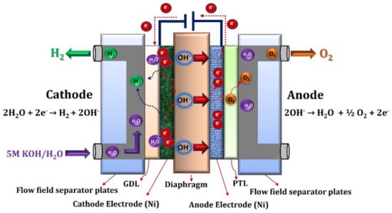
2.4.1. Alkaline Electrolysis
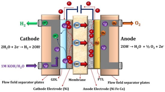
2.4.2. Anion Exchange Membrane Electrolysis
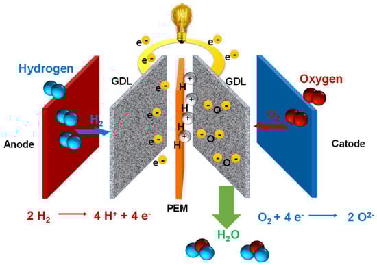
2.4.3. Proton Exchange Membrane Electrolysis
2.4.4. Solid Oxide Electrolysis
2.5. Analysis of Green Hydrogen Production Processes
| Alkaline | AEM | PEM | Solid Oxide | |
|---|---|---|---|---|
| Electrolyte | KOH/NaOH (5–7 mol/L) |
DVB polymer support with KOH/NaOH (1 mol/L) |
PFSA membrane | YSZ |
| Separator | Asbestos, Zirfon, Ni | Fumatech | Nafion® | Solid electrolyte YSZ |
| Electrode/catalyst (oxygen side) |
Nickel-coated perforated stainless steel |
Nickel or NiFeCo alloys |
Iridium oxide | Perovskites-type (LSCF, LSM) |
| Electrode/catalyst (hydrogen side) |
Nickel-coated perforated stainless steel |
Nickel | Platinum nanoparticles on carbon black |
Ni-YSZ |
| PTL anode | Nickel mesh (not always present) |
Nickel foam | Platinum-coated sintered porous titanium |
Nickel mesh or foam |
| PTL cathode | Nickel mesh | Nickel foam or carbon cloth |
Sintered porous titanium or carbon cloth |
None |
| BP anode | Nickel-coated stainless steel |
Nickel-coated stainless steel |
Platinum-coated titanium |
None |
| BP cathode | Nickel-coated stainless steel |
Nickel-coated stainless steel |
Gold-coated titanium |
Cobalt-coated stainless steel |
| Operating temperature |
70–90 °C | 40–60 °C | 50–80 °C | 700–850 °C |
| Operating pressure |
<30 bar | <35 bar | <30 bar | 1 bar |
| Nominal current density |
0.2–0.8 A/cm2 | 0.2–2 A/cm2 | 1–2 A/cm2 | 0.3–1 A/cm2 |
| Voltage range (limits) |
1.4–3.0 V | 1.4–2.0 V | 1.4–2.5 V | 1.0–1.5 V |
| Electrode area | 10,000–30,000 cm2 | <300 cm2 | 1500 cm2 | 200 cm2 |
| Efficiency | 50–68% | 52–67% | 50–68% | 75–85% |
| H2 purity | 99.9–99.9998% | 99.9–99.999% | 99.9–99.9999% | 99.9% |
| Lifetime (stack) | 60,000 h | >5000 h | 50,000–80,000 h | 20,000 h |
| Cold start | <50 min | <20 min | <20 min | >600 min |
| Stack unit size | 1 MW | 2.5 kW | 1 MW | 5 kW |
| Capital costs (stack) minimum 1 MW |
270 USD/kW | n.d. | 400 USD/kW | >2000 USD/kW |
| Capital costs (stack) minimum 10 MW |
500–1000 USD/kW | n.d. | 700–1400 USD/kW | n.d. |
| Development status | Early Adoption | Large Prototype | Early Adoption | Demonstration |
| TRL Scale | TRL 9 | TRL 6 | TRL 9 | TRL 7 |
3. Hydrogen Storage Processes
3.1. Introduction
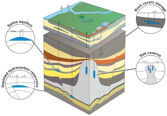
3.2. Underground Hydrogen Storage
3.3. Physical Storage
3.4. Material-Based Hydrogen Storage
4. Hydrogen Transportation Processes
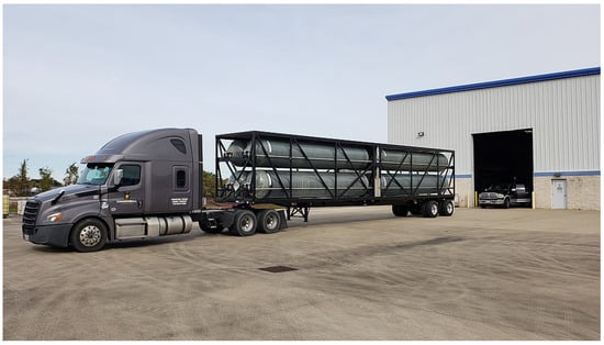
Trucks
Ship
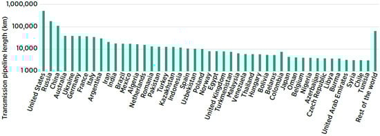
Pipelines
5. Use of Hydrogen in Energy Conversion Processes
Hydrogen Internal Combustion Engines
Hydrogen Gas Turbines
Fuel Cells
References
- Dawood, F.; Anda, M.; Shafiullah, G.M. Hydrogen production for energy: An overview. Int. J. Hydrogen Energy 2020, 45, 3847–3869.
- Hydropole. About Hydrogen. Available online: https://hydropole.ch/en/hydrogen/abouth2/ (accessed on 21 December 2022).
- Shell Deutschland Oil GmbH. Shell Hydrogen Study: Energy of the Future? Sustainable Mobility through Fuel Cells and H2. 2017. Available online: https://epub.wupperinst.org/frontdoor/deliver/index/docId/6786/file/6786_Hydrogen_Study.pdf (accessed on 10 July 2023).
- Avargani, V.M.; Zendehboudi, S.; Saady, N.M.C.; Dusseault, M.B. A comprehensive review on hydrogen production and utilization in North America: Prospects and challenges. Energy Convers. Manag. 2022, 269, 115927.
- Rizi, H.A.Y.; Shin, D. Green Hydrogen Production Technologies from Ammonia Cracking. Energies 2022, 15, 8246.
- Aziz, M. Liquid hydrogen: A review on liquefaction, storage, transportation, and safety. Energies 2021, 14, 5917.
- Engineering ToolBox. Hydrogen—Thermophysical Properties. 2008. Available online: https://www.engineeringtoolbox.com/hydrogen-d_1419.html (accessed on 5 January 2023).
- Stępień, Z. A comprehensive overview of hydrogen-fueled internal combustion engines: Achievements and future challenges. Energies 2021, 14, 6504.
- Qazi, U.Y. Future of Hydrogen as an Alternative Fuel for Next-Generation Industrial Applications; Challenges and Expected Opportunities. Energies 2022, 15, 4741.
- Martins, J.; Brito, F.P. Alternative Fuels for Internal Combustion Engines. Energies 2020, 13, 4086.
- Gao, W.; Fu, Z.; Li, Y.; Li, Y.; Zou, J. Progress of Performance, Emission, and Technical Measures of Hydrogen Fuel Internal-Combustion Engines. Energies 2022, 15, 7401.
- Pemberton, R.; Giannis, S. Unravelling the Hydrogen Regulatory Framework: Approval Process for Type IV Onboard Vehicle Hydrogen Fuel Containers; NPL Report 10.47120/npl.ENG70; National Physics Laboratory: Middlesex, UK, 2021.
- IEA—International Energy Agency. Energy Demand for Hydrogen Production by Fuel in the Net Zero Scenario, 2019–2030. 2022. Available online: https://www.iea.org/data-and-statistics/charts/energy-demand-for-hydrogen-production-by-fuel-in-the-net-zero-scenario-2019-2030 (accessed on 13 February 2023).
- Megia, P.J.; Vizcaino, A.J.; Calles, J.A.; Carrero, A. Hydrogen Production Technologies: From Fossil Fuels toward Renewable Sources. A Mini Review. Energy Fuels 2021, 35, 16403–16415.
- Amin, M.; Shah, H.H.; Fareed, A.G.; Khan, W.U.; Chung, E.; Zia, A.; Farooqi, Z.U.R.; Lee, C. Hydrogen production through renewable and non-renewable energy processes and their impact on climate change. Int. J. Hydrogen Energy 2022, 47, 33112–33134.
- Chau, K.; Djire, A.; Khan, F. Review and analysis of the hydrogen production technologies from a safety perspective. Int. J. Hydrogen Energy 2022, 47, 13990–14007.
- von Döllen, A.; Hwang, Y.; Schlüter, S. The future is colorful—an analysis of the co2 bow wave and why green hydrogen cannot do it alone. Energies 2021, 14, 5720.
- Suer, J.; Traverso, M.; Jäger, N. Carbon Footprint Assessment of Hydrogen and Steel. Energies 2022, 15, 9468.
- Jan, B.M.; Dahari, M.B.; Abro, M.; Ikram, R. Exploration of waste-generated nanocomposites as energy-driven systems for various methods of hydrogen production; A review. Int. J. Hydrogen Energy 2022, 47, 16398–16423.
- Kannah, R.Y.; Kavitha, S.; Preethi; Karthikeyan, O.P.; Kumar, G.; Dai-Viet, N.V.; Banu, J.R. Techno-economic assessment of various hydrogen production methods—A review. Bioresour. Technol. 2021, 319, 124175.
- Cho, H.H.; Strezov, V.; Evans, T.J. A review on global warming potential, challenges and opportunities of renewable hydrogen production technologies. Sustain. Mater. Technol. 2023, 35, e00567.
- Rambhujun, N.; Salman, M.S.; Wang, T.; Pratthana, C.; Sapkota, P.; Costalin, M.; Lai, Q.; Aguey-Zinsou, K.F. Renewable hydrogen for the chemical industry. MRS Energy Sustain. 2020, 7, 33.
- Sharma, S.; Agarwal, S.; Jain, A. Significance of hydrogen as economic and environmentally friendly fuel. Energies 2021, 14, 7389.
- Liu, W.; Zuo, H.; Wang, J.; Xue, Q.; Ren, B.; Yang, F. The production and application of hydrogen in steel industry. Int. J. Hydrogen Energy 2021, 46, 10548–10569.
- Hosseini, S.E.; Wahid, M.A. Hydrogen from solar energy, a clean energy carrier from a sustainable source of energy. Int. J. Energy Res. 2020, 44, 4110–4131.
- Pervaiz, E.; Ali, M.; Abbasi, M.A.; Noor, T.; Said, Z.; Alawadhi, H. Unfolding essence of nanoscience for improved water splitting hydrogen generation in the light of newly emergent nanocatalysts. Int. J. Hydrogen Energy 2022, 47, 26915–26955.
- Oruc, O.; Dincer, I. Assessing the potential of thermochemical water splitting cycles: A bridge towards for clean and sustainable hydrogen generation. Fuel 2021, 286, 119325.
- Epelle, E.I.; Desongu, K.S.; Obande, W.; Adeleke, A.A.; Ikubanni, P.P.; Okolie, J.A.; Gunes, B. A comprehensive review of hydrogen production and storage: A focus on the role of nanomaterials. Int. J. Hydrogen Energy 2022, 47, 20398–20431.
- Ravi, S.S.; Aziz, M. Clean hydrogen for mobility—Quo vadis? Int. J. Hydrogen Energy 2022, 47, 20632–20661.
- Vodovozov, V.; Raud, Z.; Petlenkov, E. Review of Energy Challenges and Horizons of Hydrogen City Buses. Energies 2022, 15, 6945.
- Chakraborty, S.; Dash, S.K.; Elavarasan, R.M.; Kaur, A.; Elangovan, D.; Meraj, S.T.; Kasinathan, P.; Said, Z. Hydrogen Energy as Future of Sustainable Mobility. Front. Energy Res. 2022, 10, 893475.
- Yue, M.; Lambert, H.; Pahon, E.; Roche, R.; Jemei, S.; Hissel, D. Hydrogen energy systems: A critical review of technologies, applications, trends and challenges. Renew. Sustain. Energy Rev. 2021, 146, 111180.
- Hermesmann, M.; Müller, T.E. Green, Turquoise, Blue, or Grey? Environmentally friendly Hydrogen Production in Transforming Energy Systems. Prog. Energy Combust. Sci. 2022, 90, 111180.
- Sircar, A.; Solanki, K.; Bist, N.; Yadav, K.; Mahanta, K. Green hydrogen: Alternate fuel for Indian energy basket. MRS Energy Sustain. 2022, 90, 100996.
- Hydrogen Europe. Hydrogen: Enabling a Zero-Emission Society. 2022. Available online: https://hydrogen.revolve.media/2022/ (accessed on 10 July 2023).
- Tarkowski, R.; Uliasz-Misiak, B. Towards underground hydrogen storage: A review of barriers. Renew. Sustain. Energy Rev. 2022, 162, 112451.
- Raza, A.; Arif, M.; Glatz, G.; Mahmoud, M.; Kobaisi, M.A.; Alafnan, S.; Iglauer, S. A holistic overview of underground hydrogen storage: Influencing factors, current understanding, and outlook. Fuel 2022, 330, 125636.
- Lebrouhi, B.E.; Djoupo, J.J.; Lamrani, B.; Benabdelaziz, K.; Kousksou, T. Global hydrogen development—A technological and geopolitical overview. Int. J. Hydrogen Energy 2022, 47, 7016–7048.
- Germscheidt, R.L.; Moreira, D.E.B.; Yoshimura, R.G.; Gasbarro, N.P.; Datti, E.; dos Santos, P.L.; Bonacin, J.A. Hydrogen Environmental Benefits Depend on the Way of Production: An Overview of the Main Processes Production and Challenges by 2050. Adv. Energy Sustain. Res. 2021, 2, 2100093.
- Okonkwo, E.C.; Al-Breiki, M.; Bicer, Y.; Al-Ansari, T. Sustainable hydrogen roadmap: A holistic review and decision-making methodology for production, utilisation and exportation using Qatar as a case study. Int. J. Hydrogen Energy 2021, 46, 35525–35549.
- Elmanakhly, F.; DaCosta, A.; Berry, B.; Stasko, R.; Fowler, M.; Wu, X.Y. Hydrogen economy transition plan: A case study on Ontario. AIMS Energy 2021, 9, 775–811.
- Kumar, S.S.; Lim, H. An overview of water electrolysis technologies for green hydrogen production. Energy Rep. 2022, 8, 13793–13813.
- Ji, M.; Wang, J. Review and comparison of various hydrogen production methods based on costs and life cycle impact assessment indicators. Int. J. Hydrogen Energy 2021, 46, 38612–38635.
- Jayakumar, A.; Madheswaran, D.K.; Kannan, A.M.; Sureshvaran, U.; Sathish, J. Can hydrogen be the sustainable fuel for mobility in India in the global context? Int. J. Hydrogen Energy 2022, 47, 33571–33596.
- IRENA—International Renewable Energy Agency. Green Hydrogen Cost Reduction: Scaling Up Electrolysers to Meet the 1.5 °C Climate Goal, 2020. Available online: https://www.irena.org/-/media/Files/IRENA/Agency/Publication/2020/Dec/IRENA_Green_hydrogen_cost_2020.pdf (accessed on 10 July 2023).
- Wu, X.; Scott, K. CuxCo3−xO4 (0 ≤ x < 1) nanoparticles for oxygen evolution in high performance alkaline exchange membrane water electrolysers. J. Mater. Chem. 2011, 21, 12344–12351.
- Xiao, L.; Zhang, S.; Pan, J.; Yang, C.; He, M.; Zhuang, L.; Lu, J. First implementation of alkaline polymer electrolyte water electrolysis working only with pure water. Energy Environ. Sci. 2012, 5, 7869–7871.
- Enapter. Technical Integration. 2023. Available online: https://handbook.enapter.com/knowledge_base/technical_integration.html#how-is-the-end-of-lifetime-of-enapter-s-electrolysers-defined (accessed on 16 March 2023).
- Salehmin, M.N.I.; Husaini, T.; Goh, J.; Sulong, A.B. High-pressure PEM water electrolyser: A review on challenges and mitigation strategies towards green and low-cost hydrogen production. Energy Convers. Manag. 2022, 268, 115985.
- Andújar, J.M.; Segura, F.; Rey, J.; Vivas, F.J. Batteries and Hydrogen Storage: Technical Analysis and Commercial Revision to Select the Best Option. Energies 2022, 15, 6196.
- Hassan, I.A.; Ramadan, H.S.; Saleh, M.A.; Hissel, D. Hydrogen storage technologies for stationary and mobile applications: Review, analysis and perspectives. Renew. Sustain. Energy Rev. 2021, 149, 111311.
- Thiyagarajan, S.R.; Emadi, H.; Hussain, A.; Patange, P.; Watson, M. A comprehensive review of the mechanisms and efficiency of underground hydrogen storage. J. Energy Storage 2022, 51, 104490.
- Egeland-Eriksen, T.; Hajizadeh, A.; Sartori, S. Hydrogen-based systems for integration of renewable energy in power systems: Achievements and perspectives. Int. J. Hydrogen Energy 2021, 46, 31963–31983.
- Amirthan, T.; Perera, M. The role of storage systems in hydrogen economy: A review. J. Nat. Gas Sci. Eng. 2022, 108, 104843.
- Quintos Fuentes, J.E.; Santos, D.M.F. Technical and Economic Viability of Underground Hydrogen Storage. Hydrogen 2023, 4, 975–1000.
- File: Hydrogen Tube Trailer.jpg—Wikimedia Commons, the Free Media Repository. 2022. Available online: https://commons.wikimedia.org/wiki/File:Hydrogen_trailer.jpg (accessed on 10 December 2023).
- IRENA. Global Hydrogen Trade to Meet the 1.5 °C Climate Goal: Part II—Technology Review of Hydrogen Carriers. 2022. Available online: www.irena.org/publications (accessed on 10 July 2023).
- Edwards, R.L.; Font-Palma, C.; Howe, J. The status of hydrogen technologies in the UK: A multi-disciplinary review. Sustain. Energy Technol. Assess. 2021, 43, 100901.
- Capurso, T.; Stefanizzi, M.; Torresi, M.; Camporeale, S.M. Perspective of the role of hydrogen in the 21st century energy transition. Energy Convers. Manag. 2022, 251, 114898.
- Atiyeh, C. Everything You Need to Know about the VW Diesel Emissions Scandal. Car Driv. 2019. Available online: https://www.caranddriver.com/news/a15339250/everything-you-need-to-know-about-the-vw-diesel-emissions-scandal/ (accessed on 10 July 2023).
- Candelaresi, D.; Valente, A.; Iribarren, D.; Dufour, J.; Spazzafumo, G. Comparative life cycle assessment of hydrogen-fuelled passenger cars. Int. J. Hydrogen Energy 2021, 46, 35961–35973.
- Netwrok, E.G.E.T. Hydrogen Gas Turbines: The Path Towards a Zero-Carbon Gas Turbine. 2020. Available online: https://etn.global/wp-content/uploads/2020/01/ETN-Hydrogen-Gas-Turbines-report.pdf (accessed on 10 July 2023).
- Thomas, J.M.; Edwards, P.P.; Dobson, P.J.; Owen, G.P. Decarbonising energy: The developing international activity in hydrogen technologies and fuel cells. J. Energy Chem. 2020, 51, 405–415.
- Tellez-Cruz, M.M.; Escorihuela, J.; Solorza-Feria, O.; Compañ, V. Proton Exchange Membrane Fuel Cells (PEMFCs): Advances and Challenges. Polymers 2021, 13, 3064.

