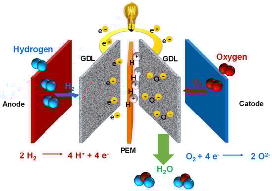
The current state of hydrogen as an energy vector is marked by its growing importance and recognition worldwide. Despite its still formidable challenges, once it achieves some maturity, it might be seen as a promising solution to address climate change, reduce emissions, and facilitate the transition towards a sustainable energy future. Collaborative international efforts highlight its significance. While challenges exist and these should not be underestimated, the momentum behind hydrogen suggests that policymakers all around the world see a promising future in the global energy transition towards a cleaner future for both developed and developing countries, and thus for the world.
1. Hydrogen
Hydrogen is the most abundant element in the Universe, and it is primarily found on Earth in molecules such as water and organic compounds [16]. It is the first and simplest element in the periodic table, having the smallest atomic mass of 1.008 g/mol and being composed of only one proton and one electron [17,18]. Atomic hydrogen does not exist under normal conditions [18]. In turn, hydrogen is found as a two-atom combination, forming the hydrogen molecule (H2).
Under normal conditions, hydrogen is a colourless and tasteless combustible gas [
26]. Because it is renewable, non-toxic, and carbon-free, it is expected to significantly improve air quality [
27]. In the remainder of the article, the term “hydrogen” will mainly be used as a synonym for the H
2 molecule.
Physical and chemical properties both have an impact on how a substance is used and handled. This is especially true when it comes to the safe handling and storage of energy carriers such as hydrogen.
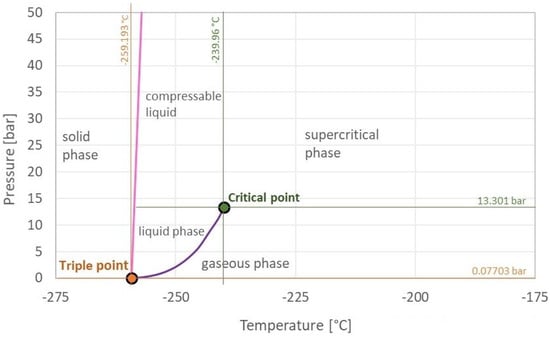
Under normal conditions, hydrogen exists as a gas. In fact, its normal boiling point at normal pressure (1.013 bar) is very close to absolute zero, at −252.8 °C (20.4 K) [
16]. Of course, temperature and pressure influence the hydrogen aggregation state. By increasing the pressure, gases can be liquefied. Regardless of the pressure, there is a critical temperature above which they can no longer be liquefied. The critical temperature for hydrogen is −240 °C (33.2 K) [
28]. As a result, in order to liquefy hydrogen, its temperature must be lower than this point. The pressure known as hydrogen’s critical pressure is 13 bar [
28]. Thus, the critical temperature and pressure of a substance, which in the case of hydrogen are −240 °C and 13 bar, define its critical point. At this point, the hydrogen density is 31 g/L [
28].
At normal pressure, the melting point of H
2 (the temperature at which it changes from solid to liquid) is −259.2 °C (13.9 K), which is slightly lower than the boiling point [
16]. A substance’s triple point is the point on the phase diagram at which all three aggregation states are in thermodynamic equilibrium. This point for hydrogen is −259.3 °C and 0.07 bar [
16]. The triple point is also the vapour–pressure curve’s minimum point. The pressure–temperature combination at which the gaseous and liquid states are in equilibrium is indicated by this curve (purple). Hydrogen is a liquid to the left of that curve and a gas to the right of that curve. Above and to the right of the critical point, hydrogen transforms into a supercritical fluid, which is neither gaseous nor liquid. In comparison to other substances, hydrogen’s vapour–pressure curve is rather steep and short [
18]. As a result, hydrogen liquefaction occurs primarily through cooling and less through compression.
Figure 3 represents the hydrogen phase diagram, which shows the critical point (green), triple point (orange), melting curve (pink), vapour–pressure curve (purple), and solid, liquid, and gaseous states of aggregation.
Figure 3. Hydrogen phase diagram [
29].
The negative Joule–Thomson coefficient of hydrogen is a unique property [
28]. Under normal conditions, when air adiabatically expands, it cools down, which is used in gas liquefaction. However, hydrogen behaves differently; when it is adiabatically expanded, it heats up. Hydrogen exhibits “normal” Joule–Thomson effect behaviour only below its inversion temperature of −73 °C (200 K) [
28].
Density is defined as the mass-to-volume ratio. At 0 °C, the density of hydrogen in its gaseous state is 0.089 g/L [
30]. With a density of 1.29 g/L, air is approximately 14 times heavier than hydrogen gas, giving hydrogen high buoyancy in the atmosphere and making it highly volatile in open air [
28]. Hydrogen has a density of 70.8 g/L in liquid form at the boiling point [
31]. It has a density of 76.3 g/L at the melting point of −259.2 °C and 1.013 bar [
18]. Thus, liquefaction increases the density of hydrogen by a factor of 800 (0.089 g/L to 70.8 g/L) while considerably decreasing its storage volume [
18]. To compare, the corresponding factors for liquefied petroleum gas (LPG) and liquefied natural gas (LNG) are approximately 250 and 600, respectively [
18].
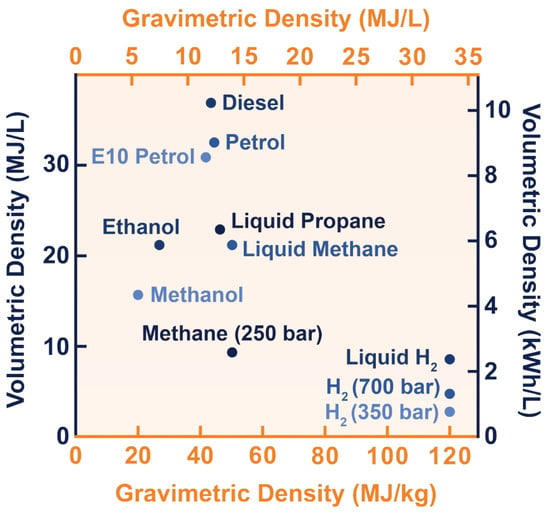
The energy content of an energy carrier greatly influences how it is stored. The calorific value of an energy source, or more accurately, its lower and higher heating values, determines its energy content. The amount of net heat released in a (theoretically) complete combustion is defined as the lower heating value (LHV). The higher heating value (HHV) additionally considers the energy released during the condensation of the water vapour produced during combustion [
18]. The calorific value usually has a mass basis, expressed in MJ/kg. It is also possible to describe it on a volume basis, MJ/L, using density (kg/L). The gravimetric and volumetric energy densities of hydrogen in various states of aggregation, as well as those of other common fuels, are depicted in
Figure 4 [
32]. As can be seen, in terms of gravimetric energy density, hydrogen has by far the highest LHV of 120.1 MJ/kg [
33]. The HHV (not shown in the figure) can be as high as 141.8 MJ/kg [
16]. As a result, the LHV is nearly three times greater than that of liquid hydrocarbons. The volumetric energy density of hydrogen, on the other hand, is relatively low. Its value is only of 0.01 MJ/L under normal conditions [
18]. As a result, in order for hydrogen to be used in practice, its density must be strongly increased so that it can be stored in a reasonably small volume.
Figure 4. Volumetric and gravimetric energy density of hydrogen in various states of aggregation, as well as of other common fuels [
34].
Another important property of hydrogen is its extreme diffusivity. Because hydrogen is the lightest of gases, it can diffuse into other media at a rate of 0.61
cm2/s, causing embrittlement in porous materials and even in metals [
33].
The flammability of hydrogen is an important chemical property. When hydrogen is burned in the open air, the flame is barely visible in daylight, as it has low heat radiation and a high ultraviolet radiation component [
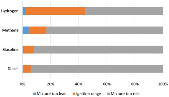
18]. Hydrogen has a broad ignition spectrum when compared to other fuels. This range is constrained by the lower and upper flammability limits, which for H
2 are 4% and 76% concentrations in air, respectively [
30]. Only methane has an upper limit close to 15%, which still falls short of that of hydrogen as shown in
Figure 5.
Figure 5. Ignition range of hydrogen and of other common fuels, adapted from [
30].
Hydrogen is an interesting fuel due to its combustion properties and absence of carbon in its composition. Its wide ignition range would allow for fairly lean air/hydrogen mixtures in internal combustion engines. While gasoline engines use a stoichiometric combustion air ratio 𝜆=1
and diesel engines use
𝜆=2, hydrogen combustion engines could use
𝜆
values as high as 10 [
18,
30]. Because lean combustions are more efficient, they use less fuel for the same amount of energy used.
Pure hydrogen has a higher self-ignition temperature than conventional fuels, at 585 °C [
33]. The minimum energy required for hydrogen ignition, on the other hand, is of only 0.02 mJ, which is lower than for other common fuels [
30]. As a result, hydrogen is classified as a highly flammable gas. A single electrostatic discharge of around 10 mJ, on the other hand, is sufficient to ignite other fuels [
18]. Hydrogen has a maximum flame speed of 346 cm/s, considerably higher than those of other common fuels [
18].
The hydrogen molecule is a relatively inert substance. However, by heating a 2:1 hydrogen/oxygen mixture to 600 °C, a chain reaction can begin, resulting in a spread of temperature rise throughout the mixture [
18]. The water vapour produced by the reaction’s heat expands to a greater volume than the original mixture. The rapid spread of water vapour causes an oxyhydrogen reaction, also known as the Knallgas reaction [
18].
Hydrogen possesses various physical and chemical properties that render it an intriguing fuel option. However, it requires careful handling and adherence to safety regulations, as not all of its properties are equally favourable.
3. Green Hydrogen Production Processes
3.1. Introduction
Hydrogen can be generated using a wide range of energy sources and technologies. It is thus an energy vector because it is a substance that stores energy as a result of the transformation of primary energy. Fossil fuel sources dominate its current production [
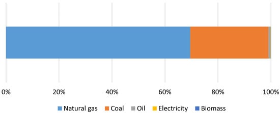
47]. As seen in
Figure 6, by the end of 2021, natural gas (69.5%), coal (29.5%), and oil (0.79%) accounted for more than 99% of global hydrogen production. Only 0.14% is generated by electricity, with the remainder (0.04%) being generated by biomass. As a result, hydrogen can be extracted not only from fossil fuels but also from biomass and even water [
48].
Figure 6. Energy demand for hydrogen production by fuel in 2021, adapted from [
47].
3.2. Hydrogen Production Processes
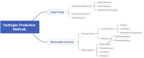
Because of their low production costs, fossil fuels continue to dominate hydrogen production. There are currently several mature technologies for producing H2 from fossil fuels, the most common of which being hydrocarbon reforming and pyrolysis. In Figure 7, one can understand the different processes for the production of hydrogen from fossil fuels and from renewable energy sources.
Figure 7. Hydrogen production processes from fossil fuels and from renewable energy sources.
3.2.1. Hydrogen Production from Fossil Fuels
Hydrocarbon reforming is the most advanced technique for producing H
2. Other reactants, such as water vapour or oxygen, are required for the process in addition to hydrocarbons. However, carbon monoxide (CO) is also produced in addition to hydrogen. Steam methane reforming (SMR) is the reaction of steam with hydrocarbons, usually natural gas (methane), at high temperatures (800–1000 °C) [
49]. Because this is a highly endothermal reaction, a significant amount of heat is required for it to take place. An alternative to steam reforming is partial oxidation (POX). It is a process that uses high temperatures to convert heavy fuel oil or coal into a mixture of H
2 and CO. One advantage of this process is that it is exothermal, which means that no external heat sources are required [
50]. When the two preceding processes, SMR and POX, are combined, the result is known as autothermal reforming (ATR). In this way, POX, in conjunction with O
2, provides the energy required for SMR, thereby rendering the process thermally neutral [
51]. It requires less energy than other processes due to its high thermal efficiency. The Global Warming Potential (GWP) of SMR and ATR is fairly high, rated at 11–13 and 13.3 kg CO
2eq/kg H
2. But it could drop to values as low as 1.14 and 0.64 kg CO
2eq/kg H
2 if carbon capture and storage are implemented [
52].
Pyrolysis is a thermal decomposition process that converts various light liquid hydrocarbons into elemental carbon (C) and hydrogen in the absence of oxygen [
53]. It is typically processed in two stages: hydrogasification and methane cracking. Because the recovered carbon is in the solid state, the pyrolysis of methane (CH
4) does not produce carbon dioxide (CO
2). Coal gasification is a thermochemical process that converts coal into synthesis gas, which is a mixture of H
2 and CO. At high temperatures and pressures, coal is converted into syngas using steam and oxygen (or air) [
54]. The main issue with this hydrogen production method is the high CO
2 emissions, at around 16 kg CO
2eq/kg H
2 [
55].
3.2.2. Hydrogen Production from Biomass
The amount of hydrogen obtained through biological processes has increased in recent years as a result of increased attention to sustainable development and waste minimisation. Dark fermentative H
2 production and photo-fermentative processes are the primary processes. Anaerobic bacteria are used in dark fermentative processes to produce H
2, organic acids, and CO
2 on carbohydrate-rich substrates in the absence of light and under low-oxygen conditions [
56]. H
2 can be produced at any time because no light is required. In photofermentation, on the other hand, photosynthetic bacteria use sunlight as an energy source and assimilate small organic molecules present in the biomass to produce H
2 and CO
2 [
57].
Some of the most efficient methods for producing H
2-rich gases from biomass are thermochemical processes. Pyrolysis, gasification, and hydrothermal liquefaction are the most common ones. When gasification and pyrolysis are used, the thermochemical conversion of dry biomass is similar to that of fossil fuels. Both the aforementioned technologies generate CO and CH
4, which can be used to increase H
2 production via steam reforming and water–gas shift reactions. Biogas reforming has an average GWP of 3.61 kg CO
2eq/kg H
2, but depending on the circumstances, it could be negative or exceed 8 kg CO
2eq/kg H
2 [
55]. Hydrogen could be obtained from humic biomass through a combination of hydrothermal liquefaction and steam reforming [
48].
3.2.3. Hydrogen Production from Water
Water is a plentiful resource for hydrogen production, and it can be split into hydrogen and oxygen with enough energy while emitting no harmful emissions. In its most basic form, water splitting uses an electric current (electrolysis) passing through two electrodes to split the water into H2 and O2. However, other energy sources, such as thermal energy (thermolysis), photonic energy (photo-electrolysis), and biophotolysis using microorganisms, can also be used to split it.
One of the most basic methods for producing hydrogen from water is electrolysis. It is the conversion of electrical energy into chemical energy in the form of hydrogen and oxygen as a by-product (this process is further detailed in the following section) [
62]. It is regarded as a promising technology, but its production costs are high. Thermolysis is a thermochemical water-splitting process that uses high temperatures to decompose water into H
2 and O
2 [
63]. Although it is a simple process, water decomposition requires temperatures above 2500 °C. Because this is a reversible process, one of the primary challenges in its application is the separation of the produced H
2 and O
2, as recombination of these gaseous products can result in an explosive mixture.
Photoelectrolysis is similar to electrolysis, but it includes the absorption of solar energy from a photoelectric cell. This is a process that requires both solar and electrical energy and converts it into chemical energy as H
2 [
64]. Biophotolysis is a photonic biochemical process that produces H
2 from water. Under anaerobic conditions, microorganisms such as green microalgae or cyanobacteria use photosynthesis to split the water molecule into H
2 and O
2 [
65]. Under these conditions, hydrogen can be produced in an aqueous environment.
3.3. Hydrogen Colour Code
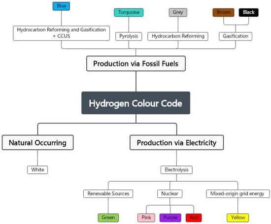
The climate benefit of hydrogen is dependent on how it is produced. As illustrated in Figure 8, hydrogen can be distinguished by colour grading based on its production method and carbon footprint.
Figure 8. The hydrogen colour spectrum.
3.3.1. Black and Brown Hydrogen
Coal is used to produce black and brown hydrogen, the colours referring to the types of coal used in the process: bituminous (black) and lignite (brown) [
66]. H
2 is produced in a process by gasifying coal, where high quantities of GHGs such as CO
2 and CO are produced [
67].
3.3.2. Grey Hydrogen
Grey hydrogen is the most common method of production right now [
68]. Hydrogen is produced using fossil fuels, and while it is not as harmful to the environment as black or brown hydrogen, the CO
2 produced is still quite significant in terms of its GWP because it is released into the atmosphere [
69,
70].
3.3.3. Turquoise Hydrogen
Turquoise hydrogen is extracted by the pyrolysis of methane [
71]. This is a relatively new process that removes solid carbon rather than emitting CO
2 [
72]. Solid carbon is an essential raw material that can be used to make tyres, plastics, batteries, etc. The process uses natural gas as a feedstock, and if the energy used is renewable, the carbon footprint will be close to zero [
19,
73].
3.3.4. Blue Hydrogen
Blue hydrogen is derived from fossil fuels, just like grey hydrogen [
74]. To reduce its emissions, however, much of the CO
2 emitted during the process is captured and stored underground or extracted as a solid and thus used [
75]. This is referred to as carbon capture, utilisation, and storage (CCUS) [
27].
3.3.5. Yellow Hydrogen
Some authors also consider yellow hydrogen, in which water electrolysis is powered by grid electricity, so its carbon footprint is dependent on how the electricity used is produced [
76].
3.3.6. Pink, Red, and Purple Hydrogen
Pink, red, and purple refer to hydrogen produced by splitting water using nuclear power plant electricity. Pink hydrogen is produced by the electrolysis of water [
77]. Red hydrogen can also be produced through thermolysis, with the chemicals used in the process being reused in a closed loop [
19]. Finally, purple hydrogen is obtained by combining nuclear energy and heat with chemo-thermal electrolysis for water splitting [
78].
3.3.7. White Hydrogen
White denotes naturally occurring hydrogen produced by a natural process within the Earth’s crust [
19]. There are projects underway to extract it, which is similar to natural gas extraction in that it requires drilling deep underground to access natural H
2 wells. It is regarded by some as the least expensive alternative to green H
2.
3.3.8. Green Hydrogen
Hydrogen that conforms with specific sustainability criteria is called green hydrogen (GH
2). However, there is no universally accepted definition, as there is no international standard for green hydrogen. Several sources refer to GH
2 as being produced through electricity generated from renewable energy sources with minimal CO
2 emission [
19,
79,
80,
81].
3.4. Water Electrolysis
Water electrolysis is an electrochemical technique for separating water to produce hydrogen and oxygen using electricity [
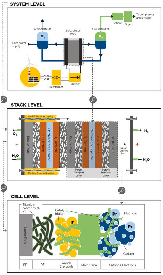
79]. Based on IRENA—International Renewable Energy Agency (Abu Dhabi, United Arab Emirates)—the electrolyser is composed of three stages (
Figure 9 [
12]):
Figure 9. Examples of the components found on water electrolysers in their three levels: system, stack and cell [
12].
-
The cell is the electrolyser’s heart and the site of the electrochemical process. Common cells consist of two electrodes—anode and cathode—immersed in a liquid electrolyte or adjacent to a solid electrolyte membrane, two porous transport layers (PTLs) that facilitate reactant transport and product removal, and bipolar plates (BPs) that provide mechanical support and flow distribution.
-
The stack generally serves a broader purpose by incorporating multiple cells connected in series, insulating material spacers between opposing electrodes, seals, frames for mechanical support, and end plates to prevent leakage and collect fluids.
-
The system level usually includes cooling equipment, hydrogen processing (e.g., for purity and compression), electricity input conversion (e.g., transformer and rectifier), water supply treatment (e.g., deionisation), and gas output (e.g., from oxygen output).
Using circulation pumps or gravity, purified water (or an aqueous solution containing elements to improve the ionic exchange) is introduced into the system. The electrolyte then flows through the BPs and PTLs to reach the electrodes.

At room temperature, the previous reaction requires a theoretical thermodynamic cell voltage of 1.23 V to split water into hydrogen and oxygen [
79]. However, the cell voltage required for efficient water splitting was experimentally determined to be 1.48 V [
79]. The additional voltage is the voltage required to overcome the kinetic and ohmic resistances of the electrolyte and the electrolyser’s cellular components [
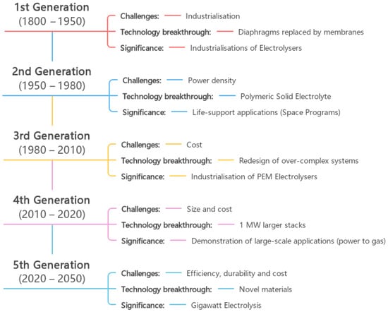
79]. This is a well-known technology for producing green hydrogen two centuries after the first water electrolysis was performed. However, it is still a technology that is not cost effective for producing large volumes of hydrogen. Water electrolysis technologies have been developed and used in industrial applications since the 18th century. Different trends influenced its development during this evolution, so it can be divided into five generations. According to IRENA—International Renewable Energy Agency—each generation of water electrolysis brings its own set of challenges, breakthroughs, and significance (
Figure 10 [
12]).
Figure 10. The five generations of water electrolysis development, adapted from [
12].
3.4.1. Alkaline Electrolysis
Alkaline water electrolysis is a well-established and mature technology for producing MW-scale industrial hydrogen in industrial applications [
79]. There have been several developments from the first introduction of water electrolysis until the operation of the first alkaline water electrolysis plant.
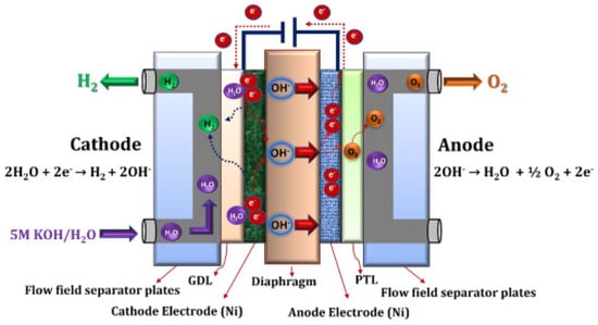
One technique for electrochemically splitting water in the presence of electricity is alkaline water electrolysis. As shown in Equations (
2) and (
3), this splitting consists of two individual reactions in each half of the cell, the hydrogen evolution reaction (HER) at the cathode, and the oxygen evolution reaction (OER) at the anode:

During this electrolysis process, two moles of alkaline solution are reduced to produce one mole of hydrogen and two moles of hydroxide ions (OH
−) [
79]. The H
2 produced can be removed from the cathode surface, and the remaining hydroxide ions are transferred to the anode side via the porous separator under the influence of the electric circuit between the anode and cathode [
79]. Already at the anode, the OH
− ions are discharged to produce half a mole of oxygen and one mole of water as shown in
Figure 11 [
79].
Figure 11. Schematic representation of the alkaline water electrolysis operating principle [
79].
3.4.2. Anion Exchange Membrane Electrolysis
Anion exchange membrane (AEM) water electrolysis is a new green hydrogen production technology [
79]. Wu and Scott published the first paper on alkaline exchange membrane water electrolysers in 2011 [
92]. The first implementation of this system took place in 2012 [
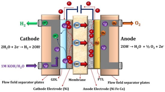
93]. The process of AEM water electrolysis is similar to that of alkaline water electrolysis [
79]. The main difference is that the diaphragms have been replaced with an anion exchange membrane. This type of water electrolysis has several advantages, including the use of less expensive transition metal catalysts rather than noble metal catalysts, and the ability to use a low-concentration alkaline solution (1 M KOH) as an electrolyte rather than a high-concentration one (5 M KOH). Despite its benefits, this technology requires additional research and development to achieve the assembly stability and cell efficiency required for commercial and/or large-scale applications. Enapter (Crespina Lorenzana, PI, Italy), the leading manufacturer of AEM electrolysers, currently reports a lifetime of 35,000 h [
94].
AEM water electrolysis is one method of electrochemically splitting water using an anion exchange membrane and electricity. The electrochemical reaction is made up of two half-cell reactions, HER and OER, which are already shown in Equations (
2) and (
3) [
79].
The water molecule is initially reduced on the cathode side by the addition of two electrons to produce H
2 and OH
− ions. Hydrogen is released from the cathode surface, and hydroxide ions are diffused across the anion exchange membrane to the anode side by the anode’s positive attraction, while electrons are transported through the external circuit [
79]. The hydroxide ions recombine as water and oxygen molecules on the anode, losing electrons in the process. The anode releases the oxygen produced.
Figure 12 illustrates the fundamental principles of AEM water electrolysis.
Figure 12. Schematic representation of the AEM water electrolysis operating principle [
79].
3.4.3. Proton Exchange Membrane Electrolysis
In 1966, General Electric Co. (Boston, MA, USA) developed the first water electrolysis device based on a proton exchange membrane (PEM) to overcome the drawbacks of alkaline water electrolysis [
96]. As an electrolyte, a sulfonated polymeric membrane is used in this technology. The ionic charge carrier is H
+, and deionized water permeates the proton conductive membrane, allowing the electrochemical reaction to function [
79]. Because of the kinetics of the hydrogen evolution reaction in PEM water electrolysis, which is faster than alkaline water electrolysis due to the highly active metal surface area of the Pt electrodes and the lower pH of the electrolyte, it typically operates at lower temperatures (30–80 °C) with higher current densities (1–2 A/cm
2) and produces high-purity (99.999%) gaseous (H
2 and O
2) [
79].
Like other water electrolysis technologies, PEM technology electrochemically splits water into hydrogen and oxygen. The water molecule is first broken down on the anode side to produce O
2, H
+ protons, and electrons as shown in Equation (
5). The produced oxygen is then expelled through the anode’s surface. The remaining protons travel to the cathode via the proton exchange membrane, while the electrons travel to the cathode via the external circuit. As shown in Equation (
4), protons and electrons recombine at the cathode to produce gaseous H
2.
3.4.4. Solid Oxide Electrolysis
A solid oxide electrolysis cell (SOEC) converts electrical energy into chemical energy. General Electric and Brookhaven National Laboratory (Upton, Suffolk County, New York, USA) pioneered the development of solid oxide water electrolysis in the USA in 1970 [
79]. This electrolyser operates at high temperatures (500–850 °C) with water in the form of steam, reducing the energy required to split the water and thus increasing energy efficiency [
18]. This increase in energy efficiency is expected to lower the cost of produced hydrogen, energy consumption accounting for the majority of the cost of H
2 production in electrolysis.
Compared to other electrolysis technologies, solid oxide water electrolysis has several advantages. Because of the high operating temperatures, the process has beneficial thermodynamics and kinetics, allowing for an increase in conversion efficiency. It is also a technology that can be easily thermally integrated with downstream chemical synthesis, such as methanol and ammonia production. It also does not require the use of noble metal electrolysers. Despite its advantages, its commercialisation has been challenged by the absence of long-term stability.
3.5. Analysis of Green Hydrogen Production Processes
Green hydrogen production (from renewable energy sources such as solar and wind) using water electrolysis technologies is expected to be a defining moment in the energy transition to meet the proposed zero-emission challenges. Water electrolysis is a well-known electrochemical process for producing green H
2 that requires widespread adoption in order to reduce production costs while maintaining high energy efficiency [
79]. As a result, advancements and innovations in current technology are required. In this context, the various technologies presented above each have unique challenges and potential solutions in terms of cost reduction and commercialisation.
Different cost-cutting strategies can be implemented at the cell level. Examples include changing the cell’s composition to use less critical materials and changing the stack design to improve the energy efficiency, durability, and current density. Another option is to increase the module’s size. This strategy should take into account the trade-off between a small module size that allows for mass manufacturing, standardisation, and replication and a large module size that can achieve cost reduction as a function of the plant size at the expense of fewer units deployed and thus less learning per deployment [
12].
Table 5 outlines the general technical characteristics of each water electrolysis technology, as well as the various materials and elements for each electrolyser component. The values associated with the operationalisation of the electrolyser systems and their estimated production cost based on plant size are then stated. Finally, each process is evaluated in terms of its TRL based on all of the values presented in the table.
Table 5. Technical characteristics of typical water electrolysis technologies: alkaline, proton exchange membrane, anion exchange membrane and solid oxide water electrolysis [
12,
79].
| |
Alkaline |
AEM |
PEM |
Solid Oxide |
| Electrolyte |
KOH/NaOH
(5–7 mol/L) |
DVB polymer support
with KOH/NaOH
(1 mol/L) |
PFSA membrane |
YSZ |
| Separator |
Asbestos, Zirfon, Ni |
Fumatech |
Nafion® |
Solid electrolyte YSZ |
Electrode/catalyst
(oxygen side) |
Nickel-coated
perforated
stainless steel |
Nickel or NiFeCo
alloys |
Iridium oxide |
Perovskites-type
(LSCF, LSM) |
Electrode/catalyst
(hydrogen side) |
Nickel-coated
perforated
stainless steel |
Nickel |
Platinum
nanoparticles on
carbon black |
Ni-YSZ |
| PTL anode |
Nickel mesh
(not always
present) |
Nickel foam |
Platinum-coated
sintered porous
titanium |
Nickel mesh
or foam |
| PTL cathode |
Nickel mesh |
Nickel foam or
carbon cloth |
Sintered porous
titanium or
carbon cloth |
None |
| BP anode |
Nickel-coated
stainless steel |
Nickel-coated
stainless steel |
Platinum-coated
titanium |
None |
| BP cathode |
Nickel-coated
stainless steel |
Nickel-coated
stainless steel |
Gold-coated
titanium |
Cobalt-coated
stainless steel |
Operating
temperature |
70–90 °C |
40–60 °C |
50–80 °C |
700–850 °C |
Operating
pressure |
<30 bar |
<35 bar |
<30 bar |
1 bar |
Nominal current
density |
0.2–0.8 A/cm2 |
0.2–2 A/cm2 |
1–2 A/cm2 |
0.3–1 A/cm2 |
Voltage range
(limits) |
1.4–3.0 V |
1.4–2.0 V |
1.4–2.5 V |
1.0–1.5 V |
| Electrode area |
10,000–30,000 cm2 |
<300 cm2 |
1500 cm2 |
200 cm2 |
| Efficiency |
50–68% |
52–67% |
50–68% |
75–85% |
| H2 purity |
99.9–99.9998% |
99.9–99.999% |
99.9–99.9999% |
99.9% |
| Lifetime (stack) |
60,000 h |
>5000 h |
50,000–80,000 h |
20,000 h |
| Cold start |
<50 min |
<20 min |
<20 min |
>600 min |
| Stack unit size |
1 MW |
2.5 kW |
1 MW |
5 kW |
Capital costs (stack)
minimum 1 MW |
270 USD/kW |
n.d. |
400 USD/kW |
>2000 USD/kW |
Capital costs (stack)
minimum 10 MW |
500–1000 USD/kW |
n.d. |
700–1400 USD/kW |
n.d. |
| Development status |
Early Adoption |
Large Prototype |
Early Adoption |
Demonstration |
| TRL Scale |
TRL 9 |
TRL 6 |
TRL 9 |
TRL 7 |
This entry is adapted from the peer-reviewed paper 10.3390/en17010180
