Submitted Successfully!
To reward your contribution, here is a gift for you: A free trial for our video production service.
Thank you for your contribution! You can also upload a video entry or images related to this topic.
Version Summary Created by Modification Content Size Created at Operation
1 -- 1534 2023-12-15 15:25:22 |
2 layout Meta information modification 1534 2023-12-18 03:55:04 |

Video Upload Options

Do you have a full video?

Confirm

Are you sure to Delete?
Cite
If you have any further questions, please contact Encyclopedia Editorial Office.
Li, R.; Zhang, Y.; Feng, Z.; Xu, J.; Wu, X.; Liu, M.; Xia, Y.; Sun, Q.; Yuan, W. Working Principle of Hydraulic Control System. Encyclopedia. Available online: https://encyclopedia.pub/entry/52815 (accessed on 29 April 2024).
Li R, Zhang Y, Feng Z, Xu J, Wu X, Liu M, et al. Working Principle of Hydraulic Control System. Encyclopedia. Available at: https://encyclopedia.pub/entry/52815. Accessed April 29, 2024.
Li, Ruichuan, Yisheng Zhang, Zhen Feng, Jikang Xu, Xiaowei Wu, Mengnan Liu, Yuhai Xia, Qiyou Sun, Wentao Yuan. "Working Principle of Hydraulic Control System" Encyclopedia, https://encyclopedia.pub/entry/52815 (accessed April 29, 2024).
Li, R., Zhang, Y., Feng, Z., Xu, J., Wu, X., Liu, M., Xia, Y., Sun, Q., & Yuan, W. (2023, December 15). Working Principle of Hydraulic Control System. In Encyclopedia. https://encyclopedia.pub/entry/52815
Li, Ruichuan, et al. "Working Principle of Hydraulic Control System." Encyclopedia. Web. 15 December, 2023.
Working Principle of Hydraulic Control System
Edit

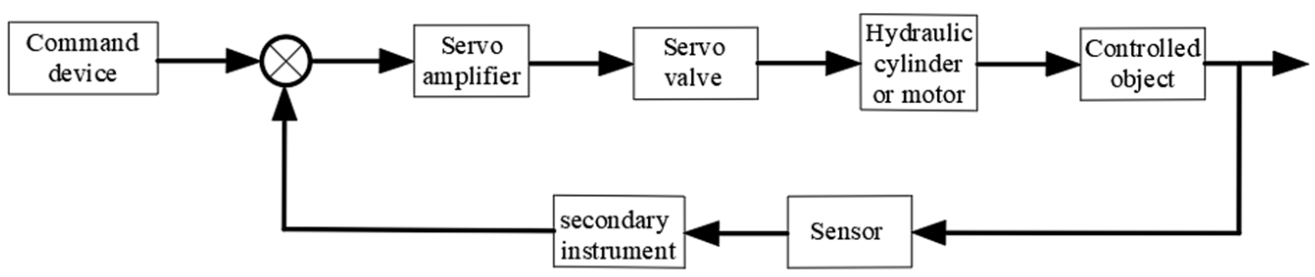
Hydraulic control systems are a feedback control system that uses hydraulic components as control and execution components, and hydraulic oil as the working medium for energy transmission. The movement of hydraulic actuators refers to the system output (including displacement, velocity, acceleration, and force), which is transmitted to the controller through feedback components. The input signal of the control component is adjusted according to the error size, so that the system output can automatically, quickly, and accurately track the system input instructions. Hydraulic control systems are classified into pump-controlled hydraulic control systems and valve-controlled hydraulic control systems based on their various control modes and valve components.

valve control system pump control system energy conservation hydraulic control system

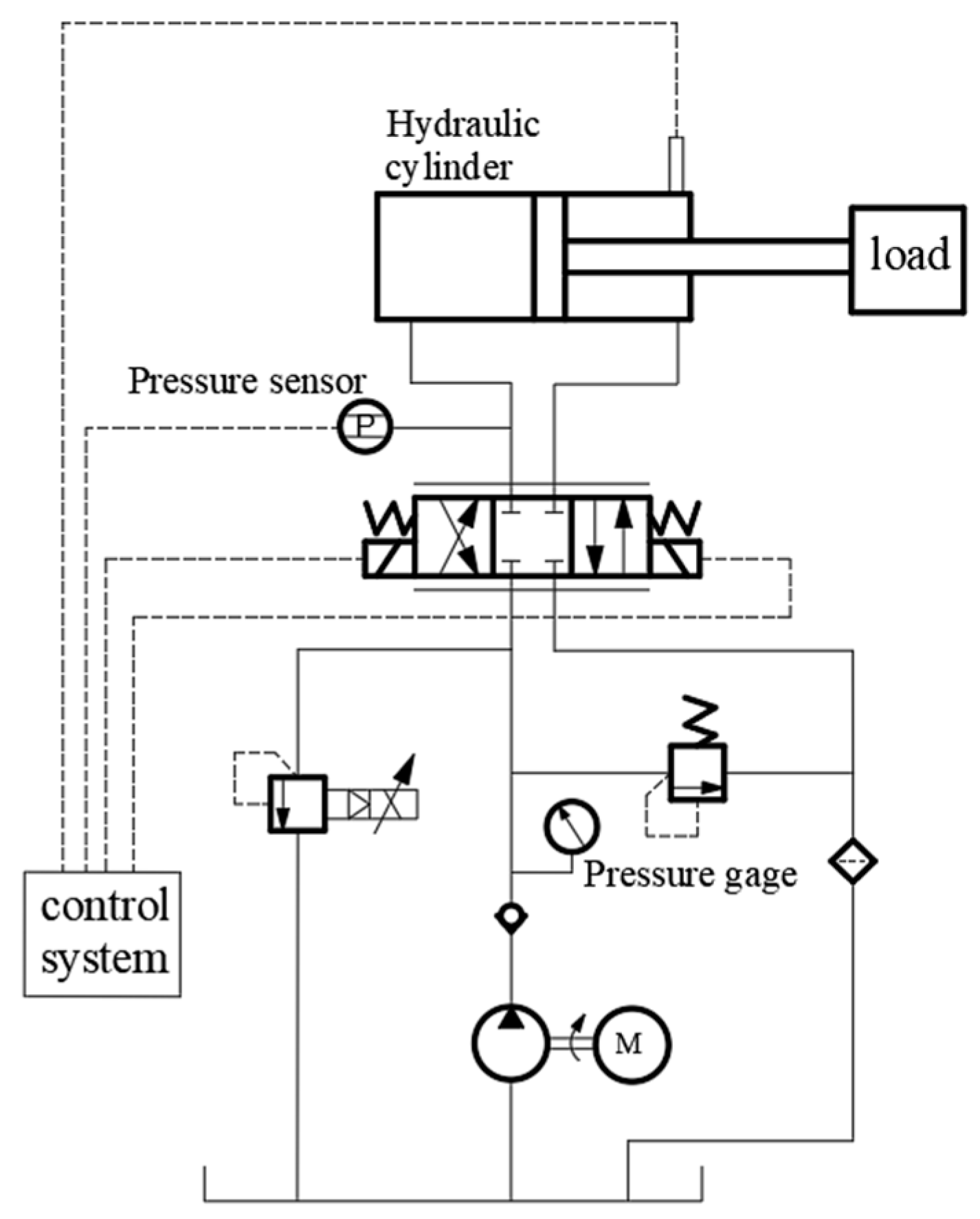
1. The Working Principle of the Valve Control System

By regulating the hydraulic valve’s (proportional, servo, and other) valve opening, the valve control system regulates the actuator’s speed. The control components of valve control systems are generally servo valves or proportional valves, as they can reach and maintain any intermediate valve core position. This can control the size of the throttling gap, thereby controlling the flow through the throttling gap. This type of valve, especially the servo valve, often works together with the bypass valve to form a series of connected throttling control system structure. There are two types of throttle control methods in valve control systems. One is the series throttle control method, where a portion of the flow generated by the quantitative pump is returned to the oil tank through the overflow valve. Another method is parallel throttle control, where a portion of the flow generated by the quantitative pump enters the hydraulic receiver through the throttle valve, and in this case, the safety valve does not work. Therefore, not all of the oil output from the quantitative pump is used to control the speed of the actuator, resulting in lower system efficiency and higher system heat generation. This makes valve control systems generally only applicable in scenarios where the speed of the actuator changes significantly and the control accuracy requirements are not high [1][2][3][4].
The valve control system adjusts and controls parameters such as pressure, flow rate, and direction of the hydraulic system by controlling the switch state of the hydraulic valve. Figure 1 shows the control block diagram of a typical electro-hydraulic proportional valve control hydraulic system. The electro-hydraulic proportional valve control system here outputs a current signal from the control system center, adjusts the servo valve opening through the action of a servo amplifier, sets the required pressure for the hydraulic system, and transmits it to the control system center through a pressure sensor. The control system center collects the actual output pressure, corrects it by comparing and analyzing it with the previously set values. Then, the obtained correction signal is analyzed as the stable output pressure of the system to ensure that the control system reaches the required pressure for the hydraulic system [5][6][7].
Figure 1. Control block diagram of valve-controlled hydraulic system.
Figure 2 shows the schematic diagram of the electro-hydraulic proportional valve-controlled hydraulic system. The operator first sets the system oil pressure target value, and the hydraulic oil in the tank is output by the oil pump. Currently, the directional valve is positioned correctly among the three locations. The main purpose of this is to convert the hydraulic energy of the hydraulic oil in the hydraulic cylinder into mechanical energy, and then use a pressure sensor to measure the hydraulic oil pressure of the system. Under the action of an A/D converter, the analog signal is converted into a digital signal and transmitted to the system. The system obtains a set of values by subtracting the target value of oil pressure from the obtained digital signal value. The difference in the obtained signal is converted and transmitted to the electro-hydraulic proportional relief valve, and the valve opening of the relief valve is adjusted to adjust the amount of hydraulic oil entering the hydraulic cylinder, thereby accurately controlling the internal oil pressure of the jack. The fundamental functions of the entire hydraulic system are to regulate the hydraulic cylinder’s displacement by the amount of oil it receives, alter the proportional relief valve’s opening area through the input current signal, and, in the end, use the cylinder’s displacement to calculate the system pressure [8][9].
Figure 2. Principle of electro-hydraulic valve control system.

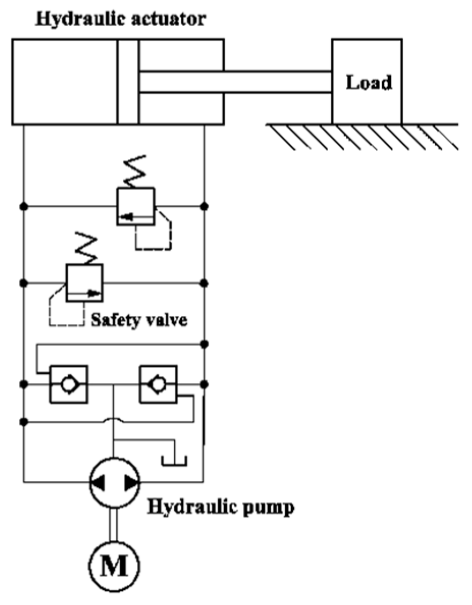
2. The Working Principle 

Volume control is another name for the pump-controlled hydraulic control system. Each actuator receives the same amount of oil input thanks to the pump-controlled hydraulic control system, which regulates actuator movement by varying the displacement of the hydraulic variable pump. Pump-controlled hydraulic control systems, as opposed to valve-controlled hydraulic control systems, use hydraulic variable displacement pumps to control actuator components, which reduces the number of hydraulic valves and the configuration of hydraulic pipelines. This improves system efficiency and considerably lowers energy losses associated with overflow throttling loss, hydraulic oil leakage, and frictional heat. The inherent frequency of the pump control system is therefore substantially lower than that of the valve control system under identical circumstances, which causes the pump control system to respond slowly. With steady or little load variations, the pump-controlled hydraulic synchronous system may achieve very tiny errors and has a high volumetric efficiency. Table 1 shows the differences between pump control systems and valve control systems [10][11][12][13][14][15]. The main difference between valve control systems and pump control systems is that the control components of valve control systems are generally proportional valves or servo valves, while the control components of pump control systems are hydraulic variable displacement pumps.
The pump control system adjusts and controls the pressure, flow, and direction parameters of the hydraulic system by controlling the operating status and flow rate of the hydraulic variable pump. Figure 3 shows the control block diagram of a typical electro-hydraulic proportional pump control hydraulic system. Compared with the electro-hydraulic proportional valve-controlled hydraulic system, the electro-hydraulic proportional pump control system here has an additional feedback path, and the sensor can collect the pressure and flow parameters in the system in real time, so that the system can change the instructions of the command device according to the working conditions, and can find problems and abnormalities in the system in time to improve the system efficiency [16][17].
Figure 3. Hydraulic schematic diagram of pump control system.
The pump control system realizes the adjustment and control of the pressure, flow, direction and other parameters of hydraulic control systems by controlling the operating state and flow of the hydraulic variable pump. Pump control systems typically consist of hydraulic variable pumps, hydraulic valves, actuators, and controllers. The principle of a typical pump control system is shown in Figure 4. In a pump-controlled system, the hydraulic variable displacement pump is responsible for providing hydraulic energy, pumping the hydraulic oil from the hydraulic tank and delivering it to the hydraulic valve through the line. Based on the input of a control signal, the hydraulic valve modifies the actuator’s movement state by controlling the hydraulic pump’s flow and start/stop functions. The actuator can be a hydraulic cylinder or a hydraulic motor that enables linear or rotary motion through the action of hydraulic oil. The controller is responsible for receiving and processing input control signals and sending control commands to hydraulic valves and hydraulic pumps to realize automatic control of the system [18][19][20].
Figure 4. Principle of valve control system.

References

  1. Sun, J.Q.; Zhang, P.Z.; Cao, X.F.; Zhai, L.J.; Han, N. Characteristic Analysis and Position Control of Valve Controlled Asymmetric Cylinder System. Mach. Tools Hydraul. 2022, 50, 29–34.
  2. Manring, N.D.; Fales, R.C. Hydraulic Control Systems, 1st ed.; John Wiley & Sons: Hoboken, NJ, USA, 2019; pp. 72–84.
  3. Qi, W.; Yang, B.; Chao, Y. Research on Hydraulic Servo Valve Control Based on Fuzzy RBF. J. Phys. Conf. Ser. 2022, 2417, 012029.
  4. Jin, X.; Chen, K.; Zhao, Y.; Ji, J.T.; Pang, J. Simulation of hydraulic transplanting robot control system based on fuzzy PID controller. Measurement 2020, 164, 108023.
  5. Pu, H.Y.; Jiang, G.; Hao, X.A.; Zou, H.F.; Liu, S.S.; Chen, Q.P.; Xu, W.G. Compound Control Strategy of Valve-controlled Asymmetric Cylinder Based on Variable Fuzzy PID Controller. Hydraul. Pneum. 2022, 46, 82–89.
  6. Liu, N.; Wang, F. Analysis and Countermeasures About Cavitation in Valve-controlled-asymmetrical-cylinder System. Hydraul. Pneum. 2021, 45, 177–182.
  7. Deng, W.X.; Yao, J.Y.; Wang, Y.Y.; Yang, X.W.; Chen, J.H. Output feedback backstepping control of hydraulic actuators with valve dynamics compensation. Mech. Syst. Signal Process 2021, 158, 107769.
  8. Chu, X.L.; Guan, Y.B. New valve control system for forging hydraulic press. Mech. Des. 2023, 40, 168–172.
  9. Shen, J.J.; Tang, Z.; Wang, B.Q.; Jia, F. Constant Speed Control of Snow Removal and Salt Sprinkle Truck Based on Optimized Fuzzy Adaptive PlD. Hydraul. Pneum. 2021, 45, 177–182.
  10. Wang, C.W.; Quan, L.; Zhang, S.J.; Meng, H.J.; Lan, Y. Reduced-order Model Based Active Disturbance Rejection Control of Hydraulic Servo System with Singular Value Perturbation Theory. ISA Trans. 2017, 68, 455–465.
  11. Xu, S.W. Development of Pump-Controlled-System Abroad. Hydraul. Pneum. Seals 2010, 30, 1–4.
  12. Liu, L.; Deng, Q.; Tang, D.W. Research on Sliding Mode Control Strategy for Electro-hydraulic Position Servo System of Valve-controlled Asymmetric Hydraulic Cylinder. Eng. Mach. 2023, 54, 78–81.
  13. Yang, X.W.; Xiong, Q.Q.; Yang, T. The Simulation Analysis for Dynamical Characteristics of the Hydraulic System Controlled by Electro-Hyaraulic Based on Power Graph and Simulink. Mech. Des. Manuf. 2019, 12, 128–130.
  14. Feng, L.J. Research on Nonlinear Models and Control Techniques for Valve-Controlled Servo Systems. Ph.D. Thesis, Beijing Jiaotong University, Beijing, China, 13 September 2021.
  15. Qin, N.; Ma, N.; Xu, B.; Zhang, Q. Design and energy efficiency analysis of valve controlled Hydraulic and electric compound drive excavator turn system. J. Mech. Eng. 2023, 21, 54–55.
  16. Helian, B.B.; Lu, L.T.; Chen, Z.; Yao, B. Trajectory Tracking Control of a Direct-drive Variable Speed Pump Control System with a Non-linear Model Compensation. Hydraul. Pneum. 2021, 45, 1–6.
  17. Liu, X.T.; Zhang, S.Z.; Zhang, L.; Zhang, X.F. Dynamic Characteristics and Compound Control of Tirple-pump Direct Driven Hydraulics. Modul. Mach. Tool Autom. Manuf. Tech. 2021, 12, 101–104.
  18. Bian, Y.M.; Yin, J.G.; Yang, J.X.; Xu, B.M. Study of Gear Pump/Motor Efficiency for Variable-Speed Pump-Controlled-Motor System. In Proceedings of the 2019 International Conference on Advances in Construction Machinery and Vehicle Engineering, Changsha, China, 14–16 May 2019.
  19. Han, Y.; Zou, B.Y. Stability Control and Simulation of Motor Speed in Pump-Control-Motor Hydraulic System. Mach. Tools Hydraul. 2023, 23, 1–9.
  20. He, J.J.; Zhang, C.; Tang, C.Q.; Li, K.; Xie, S. Study on Independent Variable Speed Pump Control System of truck Crane. M&E Eng. Technol. 2022, 51, 28–31.
More
Information
Contributors MDPI registered users' name will be linked to their SciProfiles pages. To register with us, please refer to https://encyclopedia.pub/register : , , , , , , , ,
View Times: 851
Revisions: 2 times (View History)
Update Date: 18 Dec 2023
1000/1000