Hydraulic control systems are a feedback control system that uses hydraulic components as control and execution components, and hydraulic oil as the working medium for energy transmission. The movement of hydraulic actuators refers to the system output (including displacement, velocity, acceleration, and force), which is transmitted to the controller through feedback components. The input signal of the control component is adjusted according to the error size, so that the system output can automatically, quickly, and accurately track the system input instructions. Hydraulic control systems are classified into pump-controlled hydraulic control systems and valve-controlled hydraulic control systems based on their various control modes and valve components.
1. The Working Principle of the Valve Control System
By regulating the hydraulic valve’s (proportional, servo, and other) valve opening, the valve control system regulates the actuator’s speed. The control components of valve control systems are generally servo valves or proportional valves, as they can reach and maintain any intermediate valve core position. This can control the size of the throttling gap, thereby controlling the flow through the throttling gap. This type of valve, especially the servo valve, often works together with the bypass valve to form a series of connected throttling control system structure. There are two types of throttle control methods in valve control systems. One is the series throttle control method, where a portion of the flow generated by the quantitative pump is returned to the oil tank through the overflow valve. Another method is parallel throttle control, where a portion of the flow generated by the quantitative pump enters the hydraulic receiver through the throttle valve, and in this case, the safety valve does not work. Therefore, not all of the oil output from the quantitative pump is used to control the speed of the actuator, resulting in lower system efficiency and higher system heat generation. This makes valve control systems generally only applicable in scenarios where the speed of the actuator changes significantly and the control accuracy requirements are not high [
14,
15,
16,
17].
The valve control system adjusts and controls parameters such as pressure, flow rate, and direction of the hydraulic system by controlling the switch state of the hydraulic valve.
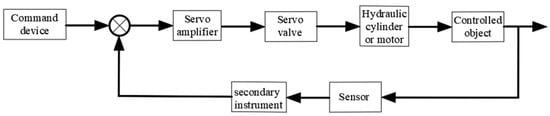
Figure 1 shows the control block diagram of a typical electro-hydraulic proportional valve control hydraulic system. The electro-hydraulic proportional valve control system here outputs a current signal from the control system center, adjusts the servo valve opening through the action of a servo amplifier, sets the required pressure for the hydraulic system, and transmits it to the control system center through a pressure sensor. The control system center collects the actual output pressure, corrects it by comparing and analyzing it with the previously set values. Then, the obtained correction signal is analyzed as the stable output pressure of the system to ensure that the control system reaches the required pressure for the hydraulic system [
18,
19,
20].
Figure 1. Control block diagram of valve-controlled hydraulic system.
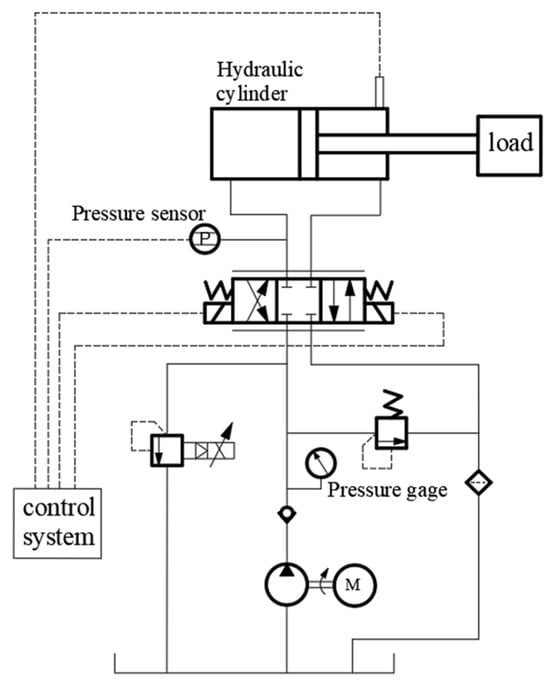
Figure 2 shows the schematic diagram of the electro-hydraulic proportional valve-controlled hydraulic system. The operator first sets the system oil pressure target value, and the hydraulic oil in the tank is output by the oil pump. Currently, the directional valve is positioned correctly among the three locations. The main purpose of this is to convert the hydraulic energy of the hydraulic oil in the hydraulic cylinder into mechanical energy, and then use a pressure sensor to measure the hydraulic oil pressure of the system. Under the action of an A/D converter, the analog signal is converted into a digital signal and transmitted to the system. The system obtains a set of values by subtracting the target value of oil pressure from the obtained digital signal value. The difference in the obtained signal is converted and transmitted to the electro-hydraulic proportional relief valve, and the valve opening of the relief valve is adjusted to adjust the amount of hydraulic oil entering the hydraulic cylinder, thereby accurately controlling the internal oil pressure of the jack. The fundamental functions of the entire hydraulic system are to regulate the hydraulic cylinder’s displacement by the amount of oil it receives, alter the proportional relief valve’s opening area through the input current signal, and, in the end, use the cylinder’s displacement to calculate the system pressure [
21,
22].
Figure 2. Principle of electro-hydraulic valve control system.
2. The Working Principle
Volume control is another name for the pump-controlled hydraulic control system. Each actuator receives the same amount of oil input thanks to the pump-controlled hydraulic control system, which regulates actuator movement by varying the displacement of the hydraulic variable pump. Pump-controlled hydraulic control systems, as opposed to valve-controlled hydraulic control systems, use hydraulic variable displacement pumps to control actuator components, which reduces the number of hydraulic valves and the configuration of hydraulic pipelines. This improves system efficiency and considerably lowers energy losses associated with overflow throttling loss, hydraulic oil leakage, and frictional heat. The inherent frequency of the pump control system is therefore substantially lower than that of the valve control system under identical circumstances, which causes the pump control system to respond slowly. With steady or little load variations, the pump-controlled hydraulic synchronous system may achieve very tiny errors and has a high volumetric efficiency.
Table 1 shows the differences between pump control systems and valve control systems [
23,
24,
25,
26,
27,
28]. The main difference between valve control systems and pump control systems is that the control components of valve control systems are generally proportional valves or servo valves, while the control components of pump control systems are hydraulic variable displacement pumps.
The pump control system adjusts and controls the pressure, flow, and direction parameters of the hydraulic system by controlling the operating status and flow rate of the hydraulic variable pump.
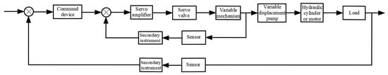
Figure 3 shows the control block diagram of a typical electro-hydraulic proportional pump control hydraulic system. Compared with the electro-hydraulic proportional valve-controlled hydraulic system, the electro-hydraulic proportional pump control system here has an additional feedback path, and the sensor can collect the pressure and flow parameters in the system in real time, so that the system can change the instructions of the command device according to the working conditions, and can find problems and abnormalities in the system in time to improve the system efficiency [
29,
30].
Figure 3. Hydraulic schematic diagram of pump control system.
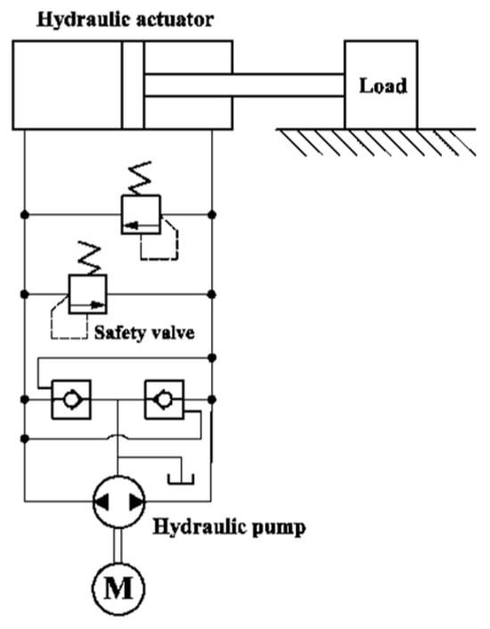
The pump control system realizes the adjustment and control of the pressure, flow, direction and other parameters of hydraulic control systems by controlling the operating state and flow of the hydraulic variable pump. Pump control systems typically consist of hydraulic variable pumps, hydraulic valves, actuators, and controllers. The principle of a typical pump control system is shown in
Figure 4. In a pump-controlled system, the hydraulic variable displacement pump is responsible for providing hydraulic energy, pumping the hydraulic oil from the hydraulic tank and delivering it to the hydraulic valve through the line. Based on the input of a control signal, the hydraulic valve modifies the actuator’s movement state by controlling the hydraulic pump’s flow and start/stop functions. The actuator can be a hydraulic cylinder or a hydraulic motor that enables linear or rotary motion through the action of hydraulic oil. The controller is responsible for receiving and processing input control signals and sending control commands to hydraulic valves and hydraulic pumps to realize automatic control of the system [
31,
32,
33].
Figure 4. Principle of valve control system.
This entry is adapted from the peer-reviewed paper 10.3390/pr11123304