Your browser does not fully support modern features. Please upgrade for a smoother experience.
Submitted Successfully!
 +1 credit
Thank you for your contribution! You can also upload a video entry or images related to this topic.
For video creation, please contact our Academic Video Service.
| Version | Summary | Created by | Modification | Content Size | Created at | Operation |
|---|---|---|---|---|---|---|
| 1 | Shijia Wang | -- | 2348 | 2023-11-21 11:10:51 | | | |
| 2 | Rita Xu | -6 word(s) | 2342 | 2023-11-22 02:33:18 | | | | |
| 3 | Rita Xu | -2 word(s) | 2340 | 2023-11-24 10:06:14 | | |
Video Upload Options
We provide professional Academic Video Service to translate complex research into visually appealing presentations. Would you like to try it?
Cite
If you have any further questions, please contact Encyclopedia Editorial Office.
Dai, W.; Wang, S.; Wang, S. Longwall Mining Automation. Encyclopedia. Available online: https://encyclopedia.pub/entry/51840 (accessed on 26 July 2026).
Dai W, Wang S, Wang S. Longwall Mining Automation. Encyclopedia. Available at: https://encyclopedia.pub/entry/51840. Accessed July 26, 2026.
Dai, Weiwei, Shijia Wang, Shibo Wang. "Longwall Mining Automation" Encyclopedia, https://encyclopedia.pub/entry/51840 (accessed July 26, 2026).
Dai, W., Wang, S., & Wang, S. (2023, November 21). Longwall Mining Automation. In Encyclopedia. https://encyclopedia.pub/entry/51840
Dai, Weiwei, et al. "Longwall Mining Automation." Encyclopedia. Web. 21 November, 2023.
Copy Citation
The shearer positioning method is of great significance to the automation of longwall mining. The research teams in the Longwall Automation Steering Committee (LASC) of Australia and China University of Mining and Technology (CUMT) have focused on shearer positioning and identified the shearer inertial navigation system, the measurement of longwall retreat and creep displacement, and the backward calibration of the shearer trajectory as three key technologies to obtain accurate shearer positioning information.
shearer positioning
longwall mining automation
inertial navigation system
1. Introduction
Longwall mining is a primary method for extracting coal from underground mines. As shown in Figure 1, three kinds of mining equipment used in the longwall face are a shearer, an armored face conveyor (AFC), and a roof support system. The shearer moves back and forth along a rail connected to the AFC, while the roof support system maintains the stability of the coal seam roof. Traditionally, the shearer and roof support system are controlled manually, which inevitably causes the rock to contaminate the coal and reduces the mining productivity. In addition, worker safety is greatly threatened because they are directly exposed to the mining worksite. Improving mining productivity, protecting worker safety, and achieving environmental sustainability are the goals that the coal mining industry has been pursuing [1][2]. Longwall mining automation is a mining process that is carried out using mining equipment without the need for manual intervention. It involves the intelligent perception of the mining environment, intelligent control of the mining equipment, and autonomous operation of the mining process [3][4]. Longwall mining automation technology has shown significant potential to achieve those goals through providing shearer positioning, face alignment, horizontal control, seam tracking, visualization and monitoring, and remote control [5][6]. Among them, shearer positioning is a foundational aspect of the autonomous mining operation, and it is a key technology that enables face alignment and horizontal control. Therefore, the accurate positioning of the shearer is of great significance to longwall mining automation.
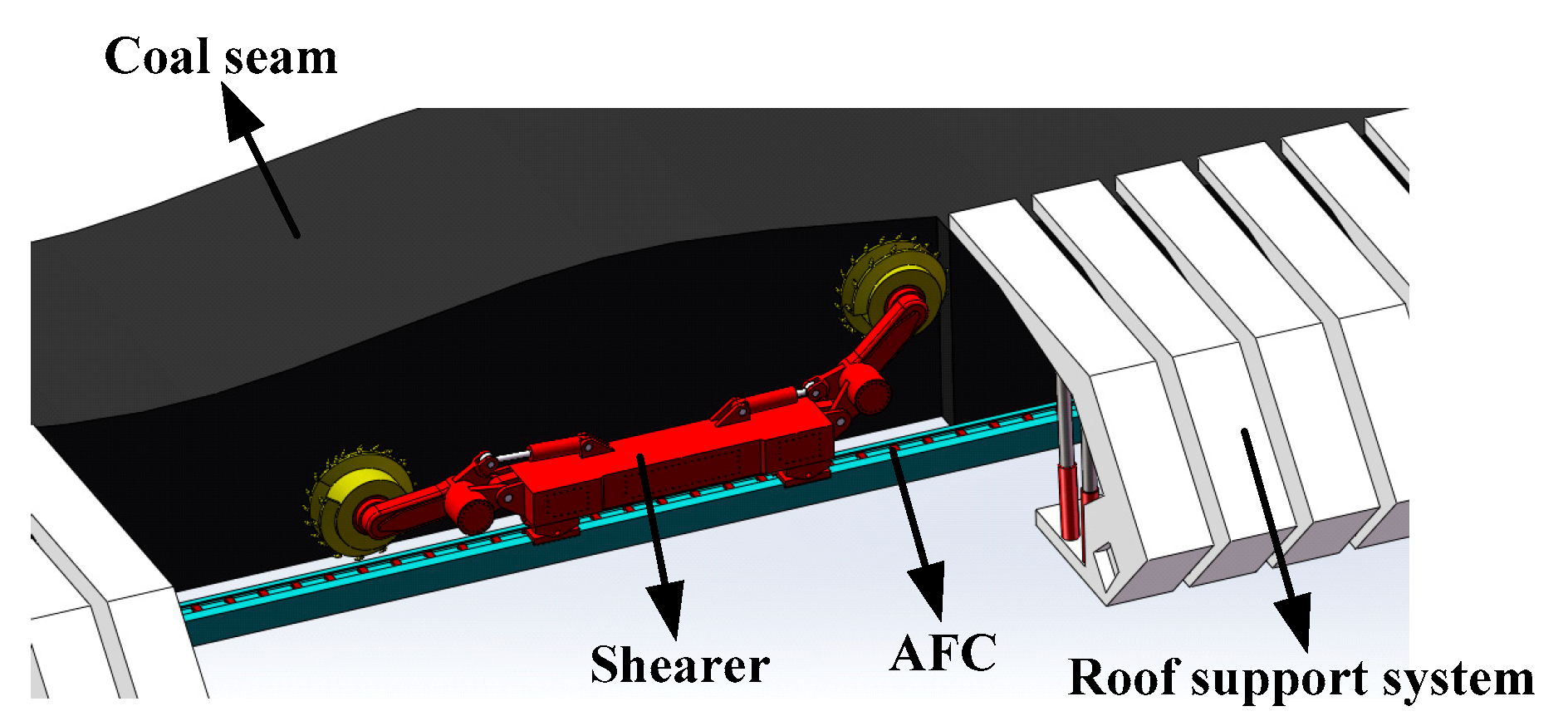
Figure 1. The diagram of the shearer, AFC, and roof support system.
As early as 2001, the Commonwealth Scientific and Industrial Research Organization (CSIRO) of Australia began developing the longwall automation technology known as the Longwall Automation Steering Committee (LASC). LASC is the abbreviation for the research team responsible for this technology. The LASC can fix the 3D position of the shearer, maintain the straightness of the conveyor and supports, raise the shearer drum automatically, and provide 3D remote monitoring video feeds [7][8][9]. The technical framework is shown in Figure 2. The latest version, LASC 2.0, has been adopted in 70% of Australia’s coal mines. DBT, JOY, and Eickhoff are all licensed manufacturers of LASC. The social benefits of LASC application have contributed to reducing the number of accidents and deaths, and the costs that are avoided as a result are likely to save mining industries millions of dollars each year. In addition, improving the accuracy of longwall mining operations and reducing the amount of waste rock leads to less environmental disruption. LASC technology has great influence on the development of longwall mining automation around the world.
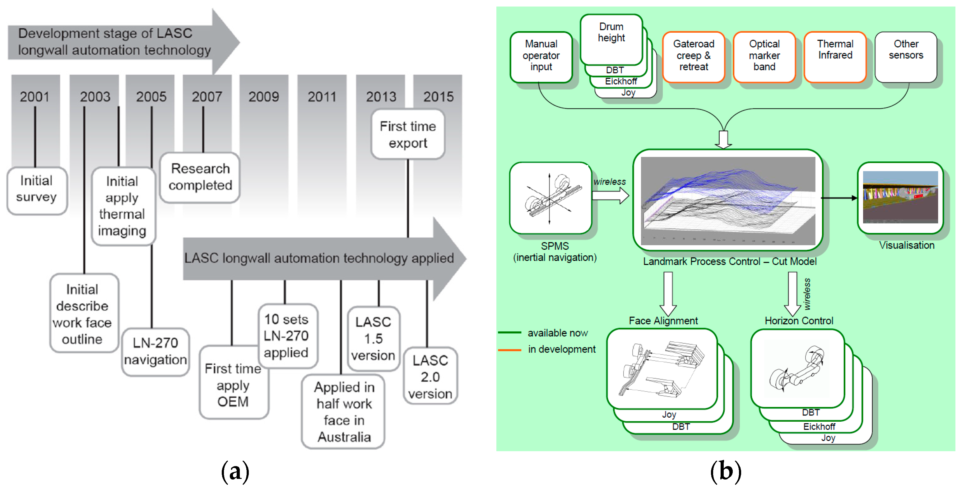
Figure 2. The diagram of (a) the development stage of LASC and (b) the technical framework of LASC.
In China, research on the automation of longwall mining commenced at a relatively later stage. Under the support of the National High-tech Research and Development Program (863 Program) and the National Natural Science Foundation of China, the research group at China University of Mining and Technology (CUMT) has devoted significant efforts to the longwall mining automation. Figure 3 shows the technical framework developed by CUMT for this purpose. The digital model of a coal seam is constructed using drill geological data and the seismic CT detection technique. Combining the digital model of the coal seam, shearer positioning technology is employed to obtain the shearer 3D positioning within the coal seam [10]. Based on this, it is possible to achieve AFC trajectory straightening and shearer cutting path planning. The industrial test was carried out and demonstrated satisfactory performance.
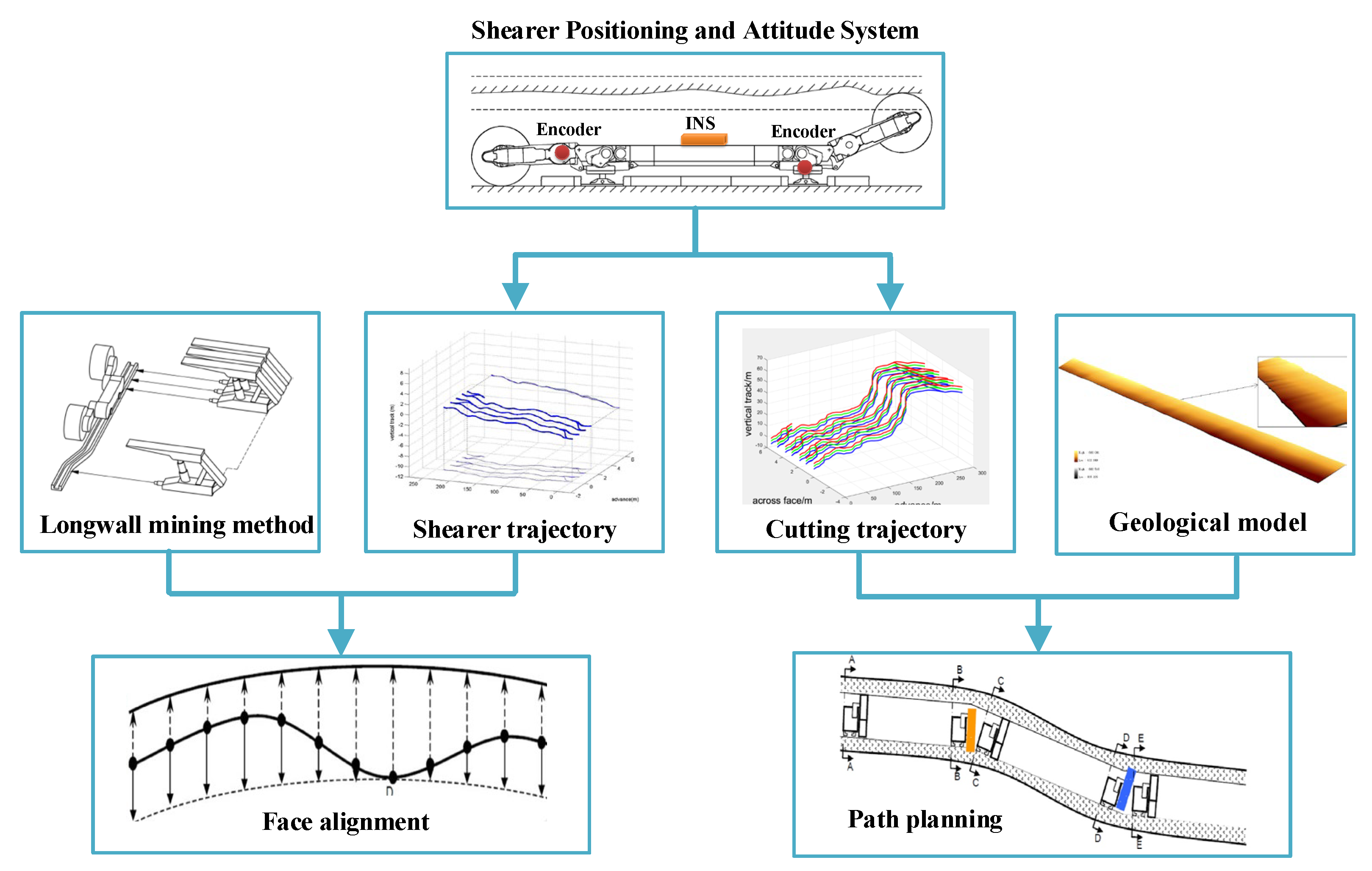
Figure 3. The technical framework of CUMT.
2. Longwall Mining Method
Longwall mining is widely recognized as a highly efficient method for extracting coal from underground mines. In a coal seam, many elongated and narrow roadways are excavated to form the boundaries of several longwall panels, as shown in Figure 4a. The roadways serve as a passageway of transportation for coal, equipment, and workers. The sectional area of roadway is approximately 5 × 4 m in general. The coal is extracted from the longwall panel, which is generally 300 min wide and 5000 min long, with a thickness ranging from 1.2 to 8.0 m. At the end of the longwall panel, the shearer, AFC, and roof support system are installed across the longwall face.
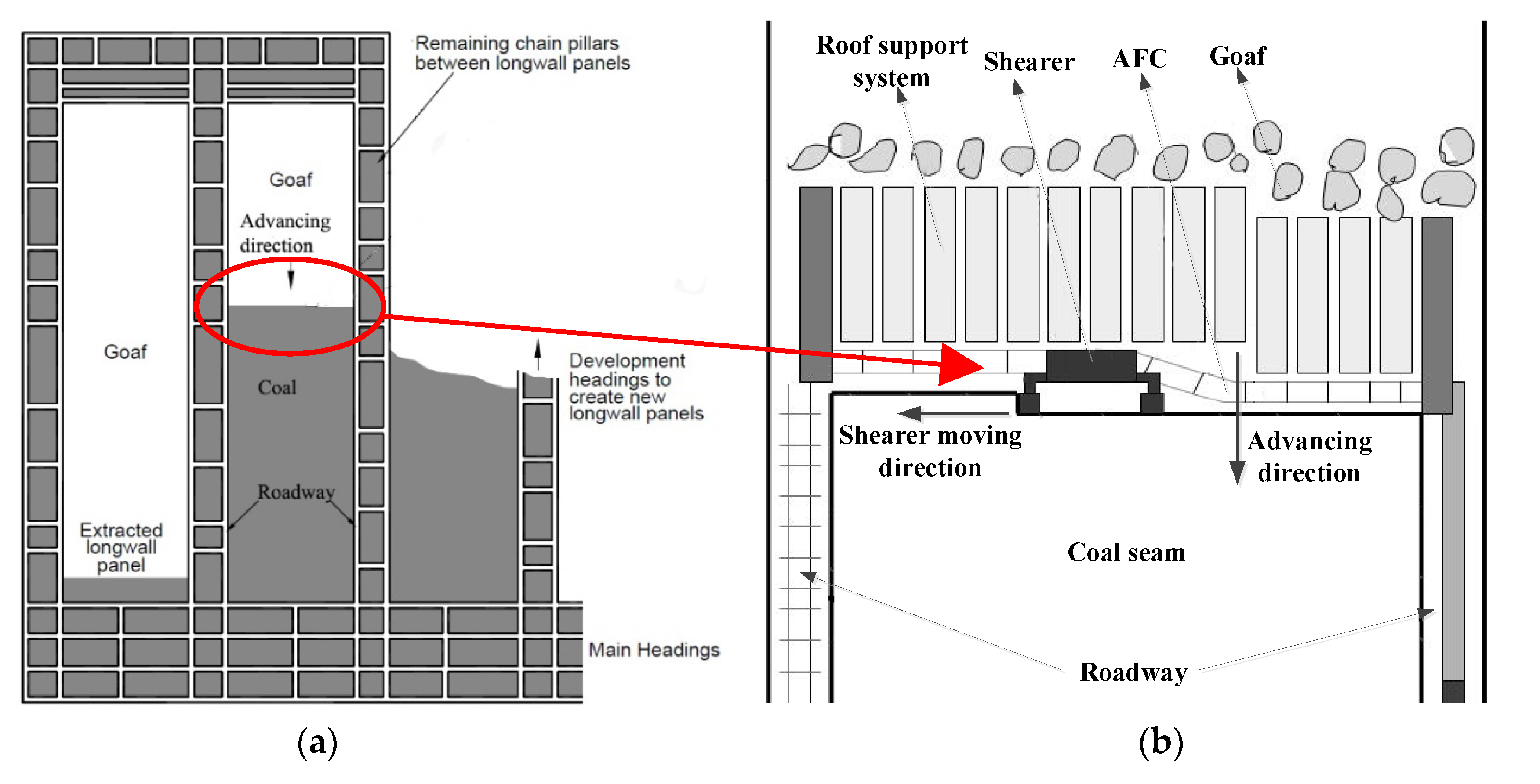
Figure 4. Typical plan view of (a) a coal mine and (b) a longwall face.
As shown in Figure 4b and Figure 5, the shearer moves along a rail associated with the AFC, cutting a 0.8 m-wide slice of coal from the coal seam. The extracted coal is deposited onto the AFC and subsequently transported far away the longwall face. When the shearer is in motion, the hydraulic push arms, which are connected to the roof support system, gradually push a section of the AFC behind the shearer along the advancing direction for the next cutting cycle. In Figure 6, the shearer is in operation during n-th cycle, while the AFC behind the shearer has been moved into the n + 1 cycle. When the coal is cut, the roof support systems support the roof of the coal seam. There are approximately 200 roof support systems in a typical longwall face. After the AFC is pushed towards the coal seam, the roof support systems are relocated along the advancing direction. Behind the roof support systems, the collapse of the roof results in the formation of a goaf.
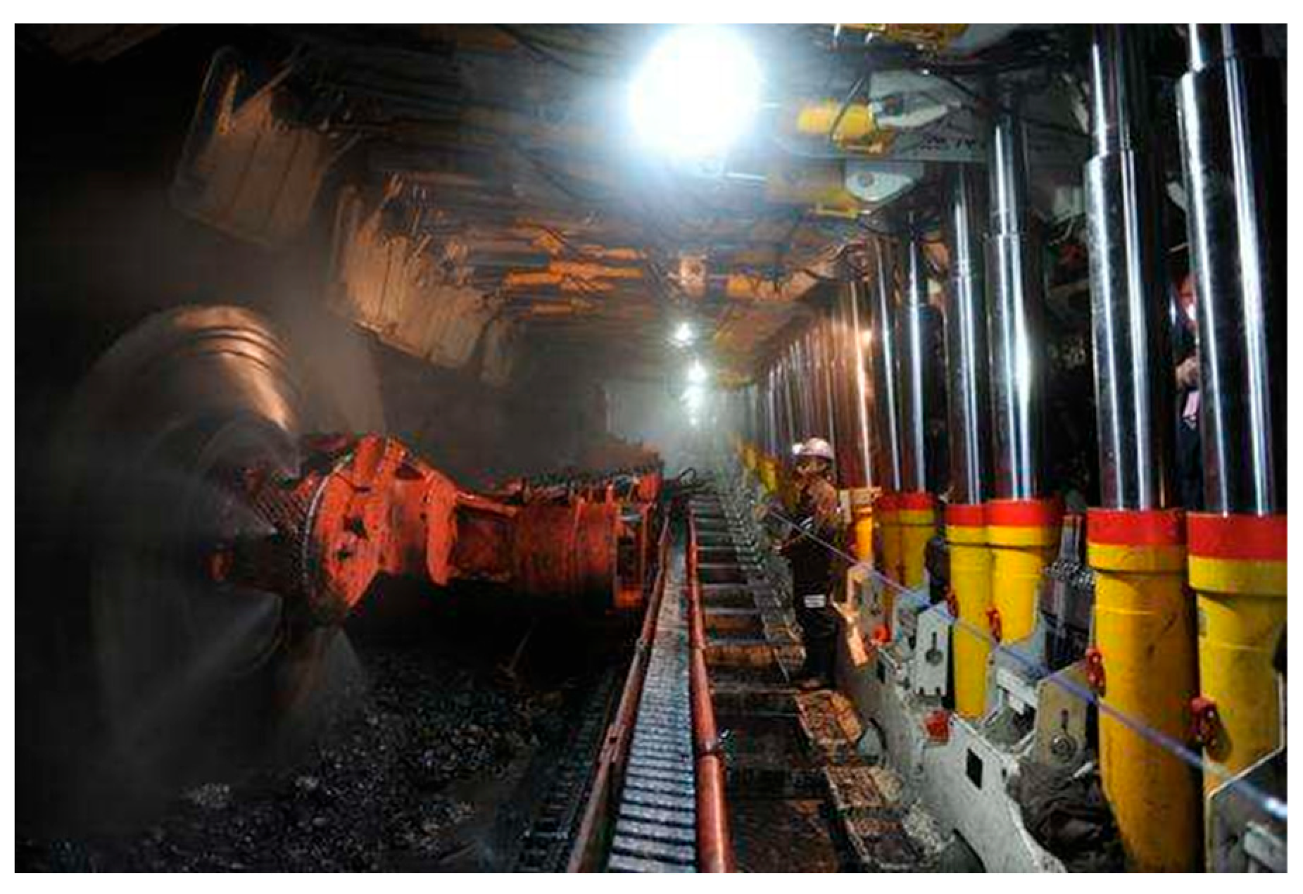
Figure 5. The shearer, AFC, and roof support system across the longwall face in an underground mine.
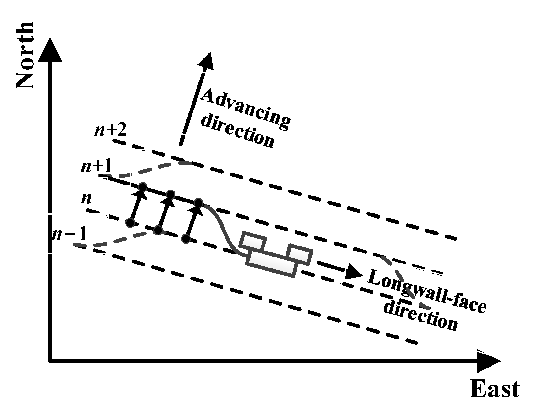
Figure 6. The diagram of the AFC profile as the shearer moves.
3. Shearer Positioning Technology
3.1. The Shearer Inertial Navigation System
Due to the unavailability of Global Position System (GPS) and BeiDou Navigation Satellite System (BDS) signals in underground environments, the positioning method based on the inertial navigation system (INS) is considered to be a feasible shearer positioning method. The INS exhibits a high level of autonomy, making it widely applied in aircraft [11], ships [12], submarines [13], and so on. The accelerometer and gyroscope serve as the core measurement units to obtain the state of an object. The tri-axis accelerometer measures the linear accelerations of an object with respect to its body reference frame in three orthogonal axes. The gyroscopes are utilized to quantify the angular velocities of rotation of the object with respect to the inertial reference frame. In summary, the navigation algorithm of the INS is founded upon the principles of Newton’s laws of motion. The attitude angles are derived through the integration of rotational angular velocities. Subsequently, the rotation matrix, also known as the direction cosine matrix (DCM), is obtained. Through integrating the measured accelerations from the accelerometers and applying the rotation matrix transformation, the velocity and position in the navigation coordinate frame can be determined [14][15].
In order to acquire the shearer position in three dimensions (3D), the LASC has developed a measurement system known as the Shearer Position Measurement System (SPMS). This system utilizes a Northrop Grumman LN270 INS, as shown in Figure 7a. The LN270 was installed within an explosion-proof enclosure in the shearer body. In addition to the INS, an odometer, connected to the shearer haulage unit, was required to accurately measure the distance traveled across the longwall face. Afterwards, the second-generation SPMS (SPMS-II) using IXSEA PHINS INS was finished, as shown in Figure 7b. Due to the noise and vibration in underground environments, the INS calculation error increases exponentially over time. That is to say, the INS exhibits a very low relative error over short time periods, but over long time periods, the error increases dramatically. Based on this, Reid et al. [16] employed zero-velocity updating technology (ZUPT) to periodically correct the velocity error during stationary motion for an INS. Furthermore, the development of integrated navigation with an INS and odometer aims to continually enhance performance. After replacing the odometer with a Doppler radar, Dunn et al. [17][18] introduced a practical and accurate aiding source. Through analyzing the longwall mining method, Reid et al. [19] determined that the horizontal closing distance between two adjacent cutting cycles remained constant. This constant value was found to be instrumental in enhancing the longtime stability of the INS. The 3D path of a shearer in an underground mine, measured using the SPMS, is shown in Figure 8.
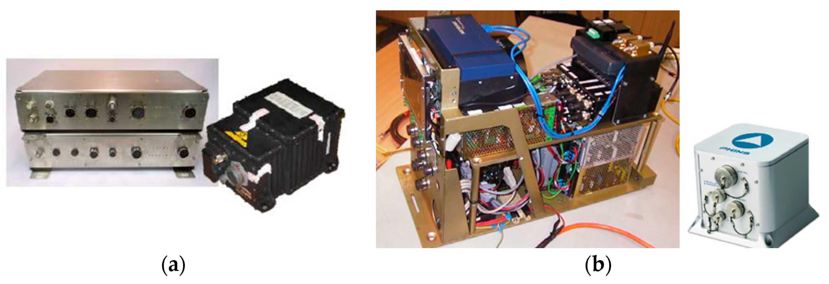
Figure 7. The shearer position measurement system (SPMS): (a) SPMS-I and (b) SPMS-II.
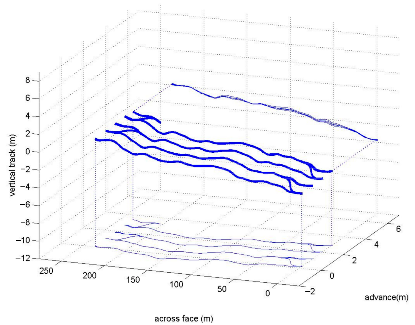
Figure 8. The shearer’s 3D path in an underground mine measured using the SPMS.
In CUMT, the authors built the Shearer Positioning and Attitude Systems (SPAS), including SPAS-I and SPAS-II, as shown in Figure 9. The Spatial FOG INS from ADVANCED NAVIGATION provided the attitude angles of heading, pitch, and roll. The axial encoder connected to the travelling unit provided the velocity value of the shearer. The shearer position was then obtained using the dead-reckoning algorithm. The effect of the installation and initial alignment noncoincidence of the INS on the shearer positioning error was analyzed, and a calibration method for the two deviation angles with the two-point method was proposed [20][21]. The current axial encoder is a 12-bit system with a resolution of 1/4096. This implies that the accuracy of INS attitude greatly affects the position error, especially the heading angle accuracy. Based on previous research, the heading angle error was found to increase at a faster rate than the pitch error and roll error over time. Furthermore, it was observed that the heading angle error directly affected the plane positioning accuracy [22][23]. According to the longwall mining method, two constraints on the shearer velocity and position were obtained. Therefore, the dynamic zero velocity update (DZUPT) model [24] and the closing path optimal estimation model [25] were built using a Kalman filter. In order to improve shearer positioning accuracy, an information filter was proposed to integrate these two models [26]. An underground field test was performed at 18,201 longwall faces in Shanxi Province, China, and Figure 10 shows the shearer trajectory acquired via the SPAS.
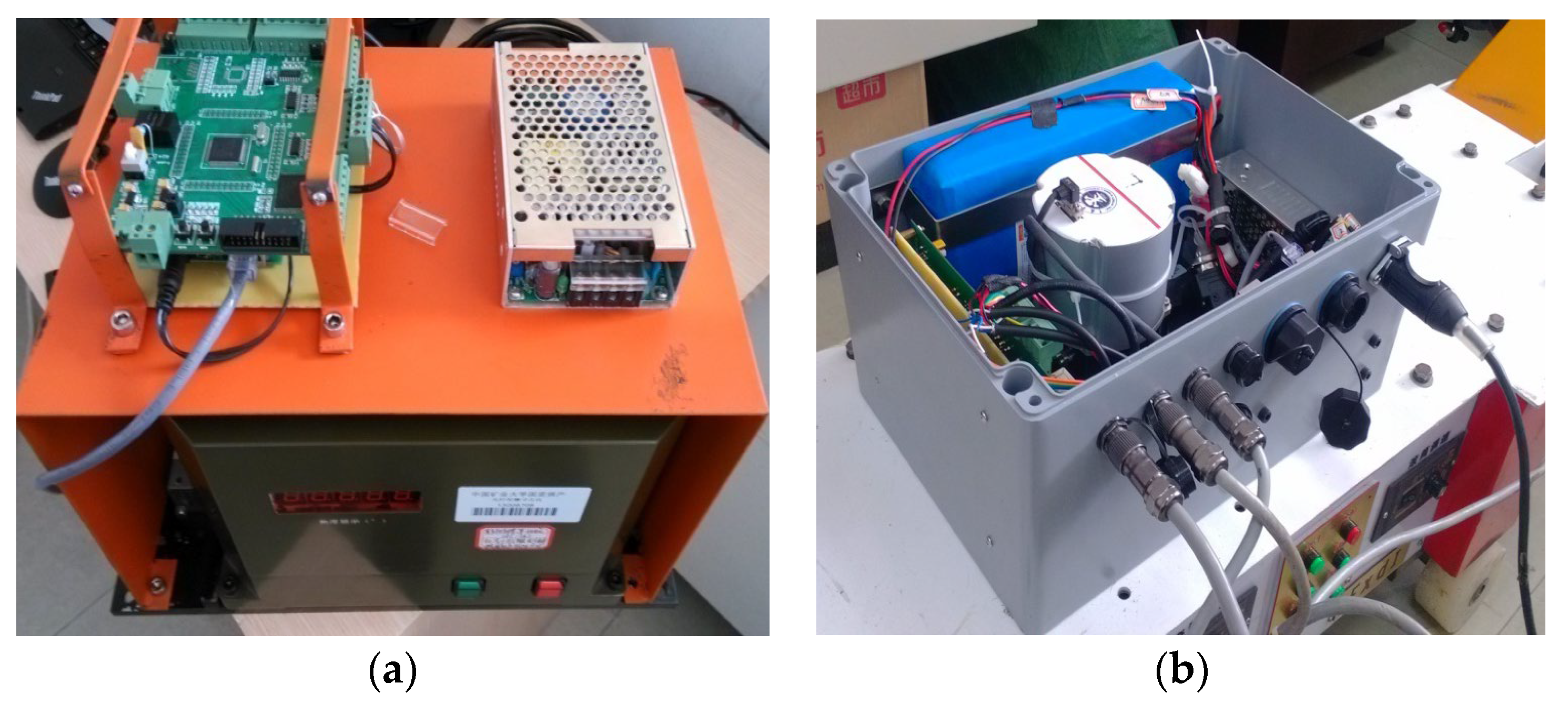
Figure 9. The shearer positioning and attitude system (SPAS): (a) SPAS-I and (b) SPAS-II.
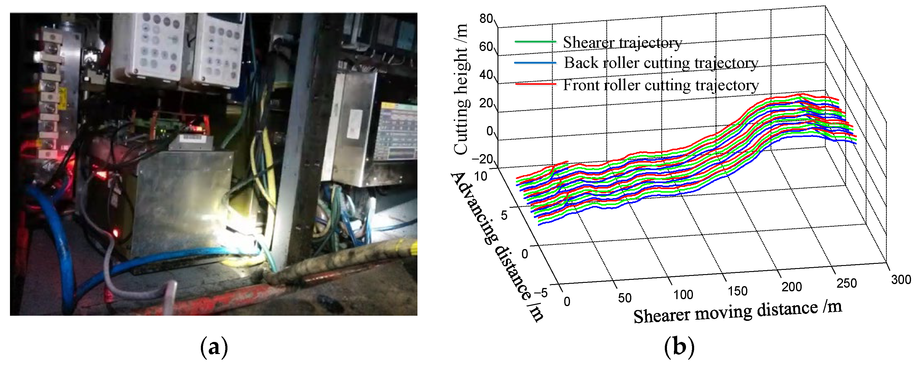
Figure 10. The diagram of (a) the underground field test in Shanxi and (b) the shearer trajectory acquired using the SPAS.
3.2. The Measurement Method of Longwall Retreat and Creep Displacements
The utilization of auxiliary sensors, ZUPT, DZUPT, and kinematics model reduced INS drift error and improved the positioning accuracy. However, due to the lack of periodic GPS calibration, the INS longtime error is still relatively large. After several cutting cycles, the shearer positioning accuracy cannot meet the requirement of the longwall mining automation. According to the longwall mining method, the shearer reciprocates between two roadways along the longwall face. When the shearer reaches the end of the longwall face, the longwall retreat and creep displacements become significant parameters to measure, which can be utilized to back-correct the shearer trajectory after the completion of each cutting cycle. As shown in Figure 11, according to the longwall mining method, the retreat displacement is actually the advancing distance of the mining equipment along the advancing direction every time.
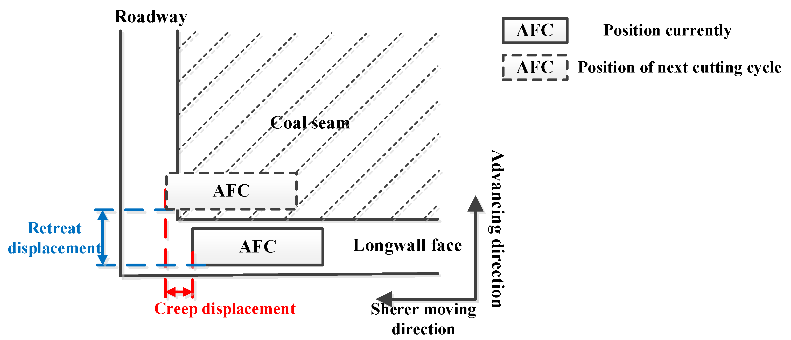
Figure 11. The diagram of the longwall retreat and creep displacements.
In the LASC, Reid et al. [19] installed the scanning laser on the roadway conveyor structure linked to the AFC to scan the roadway profile. Accordingly, the first generation of a scanning device with SICK LMS200 as the core sensor and the second generation of an explosion-proof 3D laser scanning device called ExScan have been developed. The current scan was matched to the global map with the scan-matching algorithm to acquire the retreat and creep displacements, as shown in Figure 12. However, the dust and moisture in an underground mine would greatly increase the attenuation and distortion of the laser beam, which affect the laser measurement accuracy. Then, Hargrave et al. [27][28][29] used the FMR 250 radar from Endress-Hauser company in Germany to measure the retreat and creep displacements, and a field test in Australia’s Beltana mine was carried out to verify the effectiveness of the proposed method, as shown in Figure 13. The radar is sensitive to distance information, and the creep displacement was obtained through measuring the distance between the radar and roadway wall. The number of bolt-plates on the roadway surface represented the position information, thus enabling the measurement of retreat displacement through the recognition of these bolt-plates. However, in the majority of mines, the bolt-plates lack position information, thereby limiting the applicability of this method.
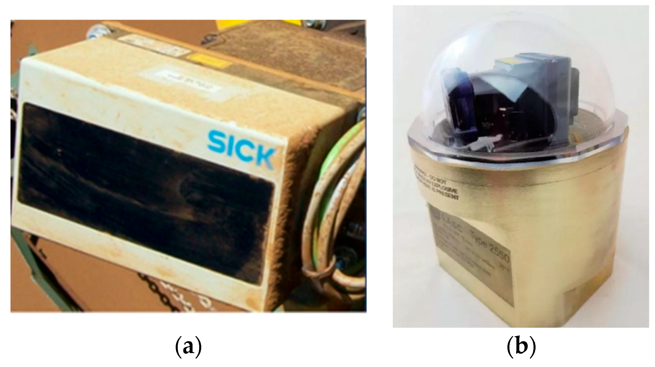
Figure 12. The diagram of (a) the SICK LMS200 scanning laser and (b) ExScan.
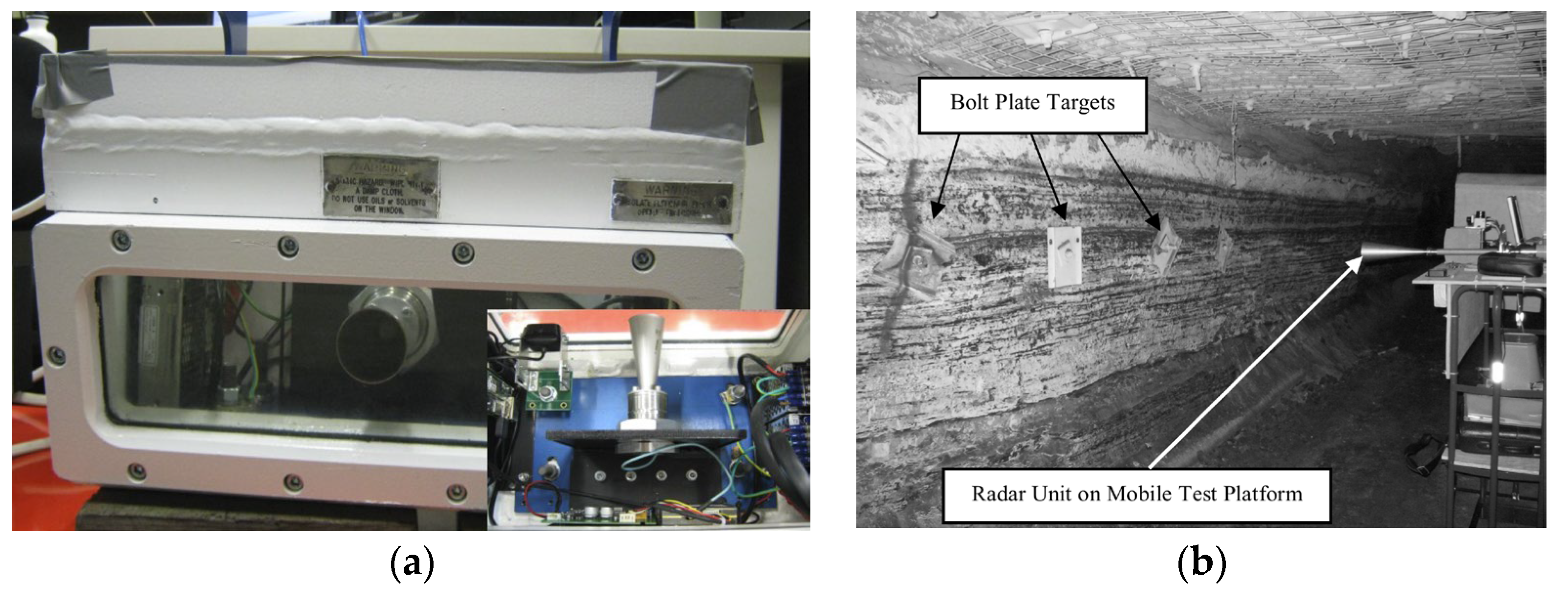
Figure 13. The diagram of (a) the Endress-Hauser FMR 250 radar and the (b) field test in an underground mine.
In CUMT, the authors provided a novel measurement solution with the ultra-wideband (UWB) radar imaging method [30]. UWB radar is characterized by a radar with a fractional bandwidth exceeding 25%. Through transmitting electromagnetic wave signals with a strong ability to penetrate a coal-dust environment, UWB radar can obtain target or scene images all day and in all weather, which has the technical advantage of application in the complex environment at the end of a longwall face. As shown in Figure 14a, the radar was mounted on a slide-way, and the slide-way was placed on the roadway conveyor structure connected to the head of the AFC. The radar was moved along the slide-way to image the bolt-plates. Two imaging results were obtained before and after the movement of the longwall face. Then, the feature-based image registration algorithm was employed to identify the correct-match pairs, and subsequently, the similarity transformation model was calculated to determine the retreat and creep displacements. The measurement device was developed (Figure 14b), and the algorithm program including radar imaging and image registration were embedded. The field text was performed in Xuzhuang Coal, China National Coal Group Corporation, and the mean values of retreat and creep measurement displacements were 8.0 mm and 8.6 mm, respectively.
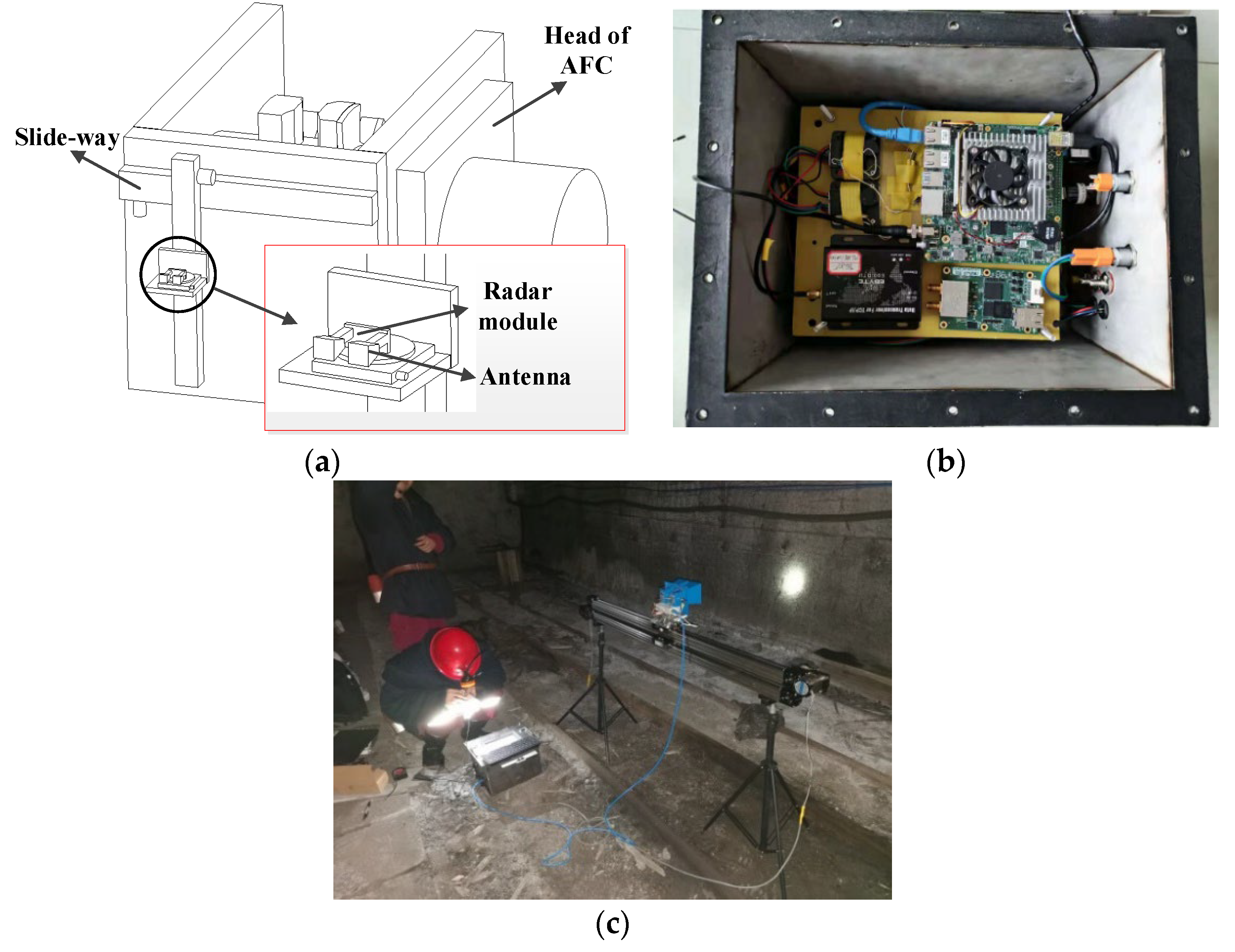
Figure 14. The diagram of (a) the measurement principle, (b) the measurement device, and (c) a field test in an underground coal mine.
References
- Singh, R.D. Principles and Practices of Modern Coal Mining; New Age International: New Delhi, India, 2004.
- Van Duin, S.; Meers, L.; Donnelly, P.; Oxley, I. Automated bolting and meshing on a continuous miner for roadway development. Int. J. Min. Sci. Technol. 2013, 23, 55–61.
- Ge, S. Key technology of intelligent coal mining equipment. Coal Sci. Technol. 2014, 42, 7–11. (In Chinese)
- Yuan, L. Scientific conception of precision coal mining. J. China Coal Soc. 2017, 42, 1–7. (In Chinese)
- Ralston, J.C.; Hargrave, C.O.; Dunn, M.T. Longwall automation: Trends, challenges and opportunities. Int. J. Min. Sci. Technol. 2017, 27, 733–739.
- Wang, J.; Huang, Z. The Recent Technological Development of Intelligent Mining in China. Engineering 2017, 3, 439–444.
- Ralston, J.; Reid, D.; Hargrave, C.; Hainsworth, D. Sensing for advancing mining automation capability: A review of underground automation technology development. Int. J. Min. Sci. Technol. 2014, 24, 305–310.
- Reid, D.C.; Hainsworth, D.W.; Ralston, J.C.; McPhee, R.J. Shearer guidance: A major advance in longwall mining. In Proceedings of the 4th International Conference on Field and Service Robotics, Lake Yamanaka, Japan, 14–16 July 2003; Springer: Berlin/Heidelberg, Germany, 2003; pp. 469–476.
- Available online: http://www.lascautomation.com/lasc-compliance.html (accessed on 18 February 2008).
- Ge, S.; Su, Z.; Li, A.; Wang, S.; Hao, S.; Liu, W.; Meng, L. Study on the positioning and orientation of a shearer based on geographic information system. J. China Coal Soc. 2015, 40, 2503–2508.
- Zhang, Q.Q.; Zhao, L.; Zhou, J.H.; Wang, B.H.; Zhang, Y.P. A real-time airborne terrain aided inertial navigation system and its performance analysis. Adv. Space Res. 2017, 60, 2751–2762.
- Zhang, C.; Guo, C.; Zhang, D. Ship navigation via GPS/IMU/LOG integration using adaptive fission particle filter. Ocean. Eng. 2018, 156, 435–445.
- Huang, H.; Chen, X.; Zhang, B.; Wang, J. High accuracy navigation information estimation for inertial system using the multi-model EKF fusing Adams explicit formula applied to underwater gliders. ISA Trans. 2017, 66, 414–424.
- Titterton, D.; Weston, J.L.; Weston, J. Strapdown Inertial Navigation Technology; IET: Stevenage, UK, 2004.
- Wang, X. The Foundation of Inertial Navigation; Northwestern Polytechnical University Press Co., Ltd.: Xi’an, China, 2012. (In Chinese)
- Reid, D.C.; Dunn, M.T.; Reid, P.B.; Ralston, J.C. A practical inertial navigation solution for continuous miner automation. In Proceedings of the 12th Coal Operators’ Conference, University of Wollongong & the Australasian Institute of Mining and Metallurgy, Perth, Australia, 8–10 October 2012; pp. 114–119. Available online: https://ro.uow.edu.au/coal/398/ (accessed on 16 February 2012).
- Dunn, M.T.; Thompson, J.P.; Reid, P.B.; Reid, D.C. High accuracy inertial navigation for underground mining machinery. In Proceedings of the 2012 IEEE International Conference on Automation Science and Engineering (CASE), Seoul, Republic of Korea, 20–24 August 2012; pp. 1179–1183.
- Dunn, M.; Reid, D.; Ralston, J. Control of automated mining machinery using aided inertial navigation. In Proceedings of the Machine Vision and Mechatronics in Practice, Toowoomba, Australia, 7–9 December 2015; Springer: Berlin/Germany, Germany, 2015; pp. 1–9.
- Reid, D.; Ralston, J.; Dunn, M.; Hainsworth, D. Longwall Shearer Automation: From Research to Reality. In Proceedings of the Machine Vision and Mechatronics in Practice, Toowoomba, Australia, 7–9 December 2015; Springer: Berlin/Heidelberg, Germany, 2015.
- Hao, S.; Li, A.; Wang, S.; Ge, Z.; Zhang, Z.; Ge, S. Effects of shearer inertial navigation installation noncoincidence on shearer positioning error. J. China Coal Soc. 2015, 40, 1963–1968. (In Chinese)
- Zhang, B.; Wang, S.; Ge, S. Effects of initial alignment error and installation noncoincidence on the shearer positioning accuracy and calibration method. J. China Coal Soc. 2017, 42, 789–795. (In Chinese)
- Li, A. Research on Shearer Absolute Positioning and Attitude Technology in Mining Area. Master’s Thesis, China University of Mining and Technology, Xuzhou, China, 2015. (In Chinese).
- Zhang, B. Research on Dynamic Accurate Positioning Method of Shearer. Master’s Thesis, China University of Mining and Technology, Xuzhou, China, 2017. (In Chinese).
- Wang, S.; Wang, S.; Zhang, B.; Ge, S. Dynamic zero-velocity update technology to shearer inertial navigation positioning. J. China Coal Soc. 2018, 43, 578–583.
- Wang, S.; Zhang, B.; Wang, S.; Ge, S. Dynamic precise positioning method of shearer based on closing path optimal estimation model. IEEE Trans. Autom. Sci. Eng. 2019, 16, 1468–1475.
- Wang, S.; Wang, S. Improving the Shearer Positioning Accuracy Using the Shearer Motion Constraints in Longwall Panels. IEEE Access 2020, 8, 52466–52474.
- Hargrave, C.O.; James, C.A.; Ralston, J.C. Infrastructure-based localisation of automated coal mining equipment. Int. J. Coal Sci. Technol. 2017, 4, 252–261.
- Hargrave, C.O.; Shuley, N.V.; Ralston, J.C.; Hainsworth, D.W. Radar level sensor for longwall creep and retreat measurement. In Proceedings of the 2007 IEEE Industry Applications Annual Meeting, New Orleans, LA, USA, 23–27 September 2007; pp. 2102–2109.
- Hargrave, C.; Clarkson, I.V.L.; Lui, H.S. Radar waypoint navigator for underground mining. In Proceedings of the 8th European Conference on Antennas and Propagation (EuCAP 2014), The Hague, The Netherlands, 6–11 April 2014; pp. 3587–3591.
- Wang, S.; Wang, S. UWB Radar Imaging Method for the Longwall Retreat and Creep Displacements Measurement in Underground Coal Mine. IEEE Trans. Autom. Sci. Eng. 2023. early access.
More
Information
Subjects:
Transportation
Contributors
MDPI registered users' name will be linked to their SciProfiles pages. To register with us, please refer to https://encyclopedia.pub/register
:
View Times:
1.7K
Revisions:
3 times
(View History)
Update Date:
24 Nov 2023
Table of Contents


Notice
You are not a member of the advisory board for this topic. If you want to update advisory board member profile, please contact office@encyclopedia.pub.
OK
Confirm
Only members of the Encyclopedia advisory board for this topic are allowed to note entries. Would you like to become an advisory board member of the Encyclopedia?
Yes
No
${ textCharacter }/${ maxCharacter }
Submit
Cancel
Back
Comments
${ item }
|
${ item.createdUser.fullName }
${ item.createdAt }
${ item.vote }
${ item.reply }
Delete
${ reply.createdUser.fullName }
${ reply.createdAt }
${ reply.vote }
Delete
There is no reply to this comment~
${ item.replyTextCharacter }/${ item.replyMaxCharacter }
Submit
Cancel
More
No more~
There is no comment~
${ textCharacter }/${ maxCharacter }
Submit
Cancel
${ selectedItem.replyTextCharacter }/${ selectedItem.replyMaxCharacter }
Submit
Cancel
Confirm
Are you sure to Delete?
Yes
No