 +1 credit
| Version | Summary | Created by | Modification | Content Size | Created at | Operation |
|---|---|---|---|---|---|---|
| 1 | Wonsuk Ko | -- | 3337 | 2023-11-16 08:00:51 | | | |
| 2 | Lindsay Dong | + 218 word(s) | 3555 | 2023-11-20 02:10:18 | | |
Video Upload Options
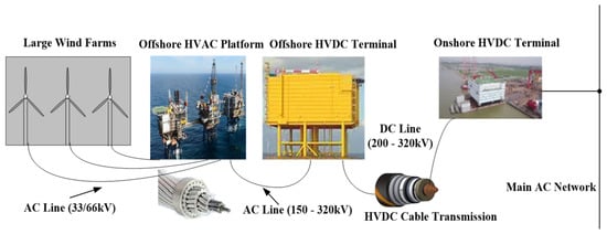
Long-distance offshore wind power transmission systems utilize multi-terminal high voltage direct current (MT-HVDC) connections based on voltage source converters (VSCs). In addition to having the potential to work around restrictions, the VSC-based MT-HVDC transmission system has significant technical and economic merits over the HVAC transmission system. Offshore wind farms (OWFs) will inevitably grow because of their outstanding resistance to climate change and ability to provide sustainable energy without producing hazardous waste. Due to stronger and more persistent sea winds, the OWF often has a higher generation capacity with less negative climate effects. The majority of modern installations are distant from the shore and produce more power than the early OWF sites, which are situated close to the shore.
1. Introduction
- (1)
-
Efficiency: Offshore projects can be more affordable, minimizing power losses in the system.
- (2)
-
Harsh environment: There is only restricted maintenance access.
- (3)
-
Footprint: The size and weight of HVDC stations have a substantial impact on the costs of investment.
- (4)
-
Reliability: The cost of unharvested energy due to transmission system outages can be critical in determining the viability of an offshore project [16].
2. HVDC Converter Technology
-
Compared to AC cables, DC cables do not exhibit the skin effect or the proximity effect.
-
Notably, in long-distance, high-voltage applications, transmission losses are reduced by a DC cable’s lack of a large reactive charging current.
-
Due to the substantial transmission loss, it is challenging for an AC system to utilize distant resources like offshore wind generation.
-
Effective active power control is present in DC systems [25].
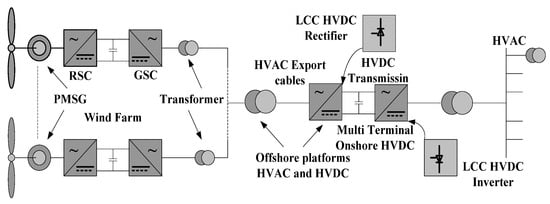
2.1. LCC
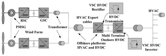
2.2. VSC
2.3. Offshore Turbine Converter Topologies
- (1)
-
LCC-based turbine converters or CSC with PWM.
- (2)
-
Interface DC/DC buck between an HVDC system and turbine VSC
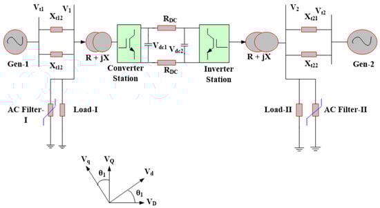
3. VSC-HVDC vs. LCC-HVDC
4. VSC-Based HVDC Scheme
VSC-Based HVDC for OWFs
5. MT-HVDC Transmission Systems
6. Economic Assessment of HVDC OWFs
6.1. Operational Costs
6.2. VSC-Based HVDC Transmission Cost Calculation
6.2.1. Capital Costs
6.2.2. Operation and Maintenance Costs
6.2.3. Cost of Losses
6.2.4. Foundation Costs for Converter Stations
6.2.5. Cost of Cable Installation and Foundation
6.3. An Economic Comparison of HVAC and HVDC Systems
-
Cost of line;
-
Cost of losses;
-
Cost of terminal.
7. Summary
-
IEC 61400-3 [71], which provides guidelines for the design, installation, operation, and maintenance of WT generators and WF control systems.
-
IEEE 1547 [72], which covers the interconnection and interoperation of distributed energy resources within the electric power system.
-
IEEE P2450 [73], which provides guidelines for the planning, design, installation, operation, and maintenance of WT generator systems, including the wind turbine, electrical equipment, and the wind farm control system.
-
IEC 62271-110 [74], which covers the HVDC systems used to transmit power from OWFs to the onshore electrical grid.
References
- Haghi, A.; Rahimi, M. Control and stability analysis of VSC-HVDC based transmission system connected to offshore wind farm. Sci. Iran. 2022, 29, 193–207.
- Raza, A.; Dianguo, X.; Xunwen, S.; Weixing, L.; Williams, B.W. A novel multiterminal VSC-HVdc transmission topology for offshore wind farms. IEEE Trans. Ind. Appl. 2016, 53, 1316–1325.
- Perveen, R.; Kishor, N.; Mohanty, S.R. Off-shore wind farm development: Present status and challenges. Renew. Sustain. Energy Rev. 2014, 29, 780–792.
- Gul, M.; Tai, N.; Huang, W.; Nadeem, M.H.; Ahmad, M.; Yu, M. Technical and economic assessment of VSC-HVDC transmission model: A case study of South-Western region in Pakistan. Electronics 2019, 8, 1305.
- Li, Z.; Song, Q.; An, F.; Zhao, B.; Yu, Z.; Zeng, R. Review on DC transmission systems for integrating large-scale offshore wind farms. Energy Convers. Econ. 2021, 2, 1–14.
- Lauria, S.; Schembari, M.; Palone, F.; Maccioni, M. Very long distance connection of gigawatt-size offshore wind farms: Extra high-voltage AC versus high-voltage DC cost comparison. IET Renew. Power Gener. 2016, 10, 713–720.
- Elliott, D.; Bell, K.R.; Finney, S.J.; Adapa, R.; Brozio, C.; Yu, J.; Hussain, K. A comparison of AC and HVDC options for the connection of offshore wind generation in Great Britain. IEEE Trans. Power Deliv. 2015, 31, 798–809.
- Yang, B.; Liu, B.; Zhou, H.; Wang, J.; Yao, W.; Wu, S.; Shu, H.; Ren, Y. A critical survey of technologies of large offshore wind farm integration: Summary, advances, and perspectives. Prot. Control Mod. Power Syst. 2022, 7, 17.
- Firestone, J.; Bates, A.W.; Prefer, A. Power transmission: Where the offshore wind energy comes home. Environ. Innov. Soc. Transit. 2018, 29, 90–99.
- Yao, W.; Jiang, L.; Wen, J.; Wu, Q.; Cheng, S. Wide-area damping controller for power system interarea oscillations: A networked predictive control approach. IEEE Trans. Control Syst. Technol. 2014, 23, 27–36.
- Brenna, M.; Foiadelli, F.; Longo, M.; Zaninelli, D. Improvement of wind energy production through HVDC systems. Energies 2017, 10, 157.
- Alassi, A.; Bañales, S.; Ellabban, O.; Adam, G.; MacIver, C. HVDC transmission: Technology review, market trends and future outlook. Renew. Sustain. Energy Rev. 2019, 112, 530–554.
- Akhmatov, V.; Callavik, M.; Franck, C.; Rye, S.E.; Ahndorf, T.; Bucher, M.K.; Müller, H.; Schettler, F.; Wiget, R. Technical guidelines and prestandardization work for first HVDC grids. IEEE Trans. Power Deliv. 2013, 29, 327–335.
- Pierri, E.; Binder, O.; Hemdan, N.G.; Kurrat, M. Challenges and opportunities for a European HVDC grid. Renew. Sustain. Energy Rev. 2017, 70, 427–456.
- Martinez-Rodrigo, F.; Ramirez, D.; Rey-Boue, A.B.; De Pablo, S.; Herrero-de Lucas, L.C. Modular multilevel converters: Control and applications. Energies 2017, 10, 1709.
- Torres Olguin, R.E.; Garces, A.; Bergna, G. HVDC transmission for offshore wind farms. In Large Scale Renewable Power Generation: Advances in Technologies for Generation, Transmission and Storage; Springer: Berlin/Heidelberg, Germany, 2014; pp. 289–310.
- Guo, C.; Zhao, W.; Yang, S.; Wu, Z.; Zhao, C. Current balancing control approach for paralleled MMC groups in hybrid LCC/VSC cascaded HVDC system. CSEE J. Power Energy Syst. 2023; early access.
- Kim, C.-K.; Sood, V.K.; Jang, G.-S.; Lim, S.-J.; Lee, S.-J. HVDC Transmission: Power Conversion Applications in Power Systems; John Wiley & Sons: Hoboken, NJ, USA, 2009.
- Bresesti, P.; Kling, W.L.; Hendriks, R.L.; Vailati, R. HVDC connection of offshore wind farms to the transmission system. IEEE Trans. Energy Convers. 2007, 22, 37–43.
- Liang, J.; Jing, T.; Gomis-Bellmunt, O.; Ekanayake, J.; Jenkins, N. Operation and control of multiterminal HVDC transmission for offshore wind farms. IEEE Trans. Power Deliv. 2011, 26, 2596–2604.
- Lu, W.; Ooi, B.-T. Optimal acquisition and aggregation of offshore wind power by multiterminal voltage-source HVDC. IEEE Trans. Power Deliv. 2003, 18, 201–206.
- Negra, N.B.; Todorovic, J.; Ackermann, T. Loss evaluation of HVAC and HVDC transmission solutions for large offshore wind farms. Electr. Power Syst. Res. 2006, 76, 916–927.
- Wang, L.; Thi, M.S.-N. Stability analysis of four PMSG-based offshore wind farms fed to an SG-based power system through an LCC-HVDC link. IEEE Trans. Ind. Electron. 2013, 60, 2392–2400.
- Xu, L.; Andersen, B.R. Grid connection of large offshore wind farms using HVDC. Wind Energy 2006, 9, 371–382.
- Van Hertem, D.; Ghandhari, M. Multi-terminal VSC HVDC for the European supergrid: Obstacles. Renew. Sustain. Energy Rev. 2010, 14, 3156–3163.
- Rao, S.B.; Kumar, Y.P.; Amir, M.; Ahmad, F. An Adaptive Neuro-Fuzzy Control Strategy for Improved Power Quality in Multi-Microgrid Clusters. IEEE Access 2022, 10, 128007–128021.
- Roncero-Sánchez, P.; Parreño Torres, A.; Vázquez, J.; López-Alcolea, F.J.; Molina-Martínez, E.J.; Garcia-Torres, F. Multiterminal hvdc system with power quality enhancement. Energies 2021, 14, 1306.
- Li, Y.; Tang, G.; An, T.; Pang, H.; Wang, P.; Yang, J.; Wu, Y.; He, Z. Power compensation control for interconnection of weak power systems by VSC-HVDC. IEEE Trans. Power Deliv. 2016, 32, 1964–1974.
- Watson, N.R.; Watson, J.D. An overview of HVDC technology. Energies 2020, 13, 4342.
- Lee, D.; Kim, H.; Lee, J.; Han, C.; Jang, G. Autonomous frequency smoothing control of offshore wind-linked HVDC for low-inertia system. Electr. Power Syst. Res. 2023, 216, 109034.
- Ekanayake, J.B.; Jenkins, N.; Liyanage, K.; Wu, J.; Yokoyama, A. Smart Grid: Technology and Applications; John Wiley & Sons: Hoboken, NJ, USA, 2012.
- Ashabani, M.; Mohamed, Y.A.-R.I. Novel comprehensive control framework for incorporating VSCs to smart power grids using bidirectional synchronous-VSC. IEEE Trans. Power Syst. 2013, 29, 943–957.
- Musasa, K.; Nwulu, N.I.; Gitau, M.N.; Bansal, R.C. Review on DC collection grids for offshore wind farms with high-voltage DC transmission system. IET Power Electron. 2017, 10, 2104–2115.
- Shao, S.J.; Agelidis, V.G. Review of DC system technologies for large scale integration of wind energy systems with electricity grids. Energies 2010, 3, 1303–1319.
- Meyer, C.; Hoing, M.; Peterson, A.; De Doncker, R.W. Control and design of DC grids for offshore wind farms. IEEE Trans. Ind. Appl. 2007, 43, 1475–1482.
- Ryndzionek, R.; Sienkiewicz, Ł. Evolution of the HVDC link connecting offshore wind farms to onshore power systems. Energies 2020, 13, 1914.
- Keshavarz, S. Design and Evaluation of an Active Rectifier for a 4.1 MW Off-Shore Wind Turbine. Master’s Thesis, Chalmers University of Technology, Gothenburg, Sweden, 2011.
- Dambone Sessa, S.; Chiarelli, A.; Benato, R. Availability analysis of HVDC-VSC systems: A review. Energies 2019, 12, 2703.
- Zhang, Z.; Xu, Z.; Xue, Y.; Tang, G. DC-side harmonic currents calculation and DC-loop resonance analysis for an LCC–MMC hybrid HVDC transmission system. IEEE Trans. Power Deliv. 2014, 30, 642–651.
- Fu, Y.; Wang, C.; Tian, W.; Shahidehpour, M. Integration of large-scale offshore wind energy via VSC-HVDC in day-ahead scheduling. IEEE Trans. Sustain. Energy 2015, 7, 535–545.
- Morawiec, M. The adaptive backstepping control of permanent magnet synchronous motor supplied by current source inverter. IEEE Trans. Ind. Inform. 2012, 9, 1047–1055.
- Morawiec, M.; Lewicki, A. Power electronic transformer based on cascaded H-bridge converter. Bull. Pol. Acad. Sci. Tech. Sci. 2017, 65, 675–683.
- Dworakowski, P.; Wilk, A.; Michna, M.; Lefebvre, B.; Sixdenier, F.; Mermet-Guyennet, M. Effective permeability of multi air gap ferrite core 3-phase medium frequency transformer in isolated DC-DC converters. Energies 2020, 13, 1352.
- Peake, O. The history of high voltage direct current transmission. Aust. J. Multi-Discip. Eng. 2010, 8, 47–55.
- Stan, A.; Costinaș, S.; Ion, G. Overview and Assessment of HVDC Current Applications and Future Trends. Energies 2022, 15, 1193.
- Melhem, Z. Electricity Transmission, Distribution and Storage Systems; Woodhead Publishing: Cambridge, UK, 2013.
- Xing, Y.; Wang, H.; Zhang, T.; Wang, S.; Zhao, B.; Wang, T. An Improved NLM Strategy for MMC Emergency Power Control. In Proceedings of the 2020 IEEE/IAS Industrial and Commercial Power System Asia (I&CPS Asia), Weihai, China, 13–15 July 2020; pp. 1251–1255.
- Adam, G.P.; Davidson, I.E. Robust and generic control of full-bridge modular multilevel converter high-voltage DC transmission systems. IEEE Trans. Power Deliv. 2015, 30, 2468–2476.
- Li, R.; Xu, L.; Yu, L.; Yao, L. A hybrid modular multilevel converter with reduced full-bridge submodules. IEEE Trans. Power Deliv. 2019, 35, 1876–1885.
- Davidson, I.E.; Oni, O.E.; Aluko, A.; Buraimoh, E. Enhancing the Performance of Eskom’s Cahora Bassa HVDC Scheme and Harmonic Distortion Minimization of LCC-HVDC Scheme Using the VSC-HVDC Link. Energies 2022, 15, 4008.
- Acaroğlu, H.; Márquez, F.P.G. High voltage direct current systems through submarine cables for offshore wind farms: A life-cycle cost analysis with voltage source converters for bulk power transmission. Energy 2022, 249, 123713.
- Kawaguchi, T.; Sakazaki, T.; Isobe, T.; Shimada, R. Offshore-wind-farm configuration using diode rectifier with MERS in current link topology. IEEE Trans. Ind. Electron. 2012, 60, 2930–2937.
- Parastar, A.; Kang, Y.C.; Seok, J.-K. Multilevel modular DC/DC power converter for high-voltage DC-connected offshore wind energy applications. IEEE Trans. Ind. Electron. 2014, 62, 2879–2890.
- Parker, M.A.; Ran, L.; Finney, S.J. Distributed control of a fault-tolerant modular multilevel inverter for direct-drive wind turbine grid interfacing. IEEE Trans. Ind. Electron. 2012, 60, 509–522.
- Garcés, A.; Molinas, M. A study of efficiency in a reduced matrix converter for offshore wind farms. IEEE Trans. Ind. Electron. 2011, 59, 184–193.
- Liserre, M.; Cardenas, R.; Molinas, M.; Rodriguez, J. Overview of multi-MW wind turbines and wind parks. IEEE Trans. Ind. Electron. 2011, 58, 1081–1095.
- Gomis-Bellmunt, O.; Egea-Alvarez, A.; Junyent-Ferré, A.; Liang, J.; Ekanayake, J.; Jenkins, N. Multiterminal HVDC-VSC for offshore wind power integration. In Proceedings of the 2011 IEEE Power and Energy Society General Meeting, Detroit, MI, USA, 24–28 July 2011; pp. 1–6.
- Gomis-Bellmunt, O.; Junyent-Ferré, A.; Sumper, A.; Galceran-Arellano, S. Maximum generation power evaluation of variable frequency offshore wind farms when connected to a single power converter. Appl. Energy 2010, 87, 3103–3109.
- Jovcic, D. Offshore wind farm with a series multiterminal CSI HVDC. Electr. Power Syst. Res. 2008, 78, 747–755.
- Gomis-Bellmunt, O.; Junyent-Ferre, A.; Sumper, A.; Bergas-Jane, J. Control of a wind farm based on synchronous generators with a central HVDC-VSC converter. IEEE Trans. Power Syst. 2010, 26, 1632–1640.
- Xu, L.; Yao, L.; Sasse, C. Grid integration of large DFIG-based wind farms using VSC transmission. IEEE Trans. Power Syst. 2007, 22, 976–984.
- Thomsen, K. Offshore Wind: A Comprehensive Guide to Successful Offshore Wind Farm Installation; Academic Press: Cambridge, MA, USA, 2014.
- Ioannou, A.; Angus, A.; Brennan, F. Parametric CAPEX, OPEX, and LCOE expressions for offshore wind farms based on global deployment parameters. Energy Sources Part B Econ. Plan. Policy 2018, 13, 281–290.
- Sharifabadi, K.; Harnefors, L.; Nee, H.-P.; Norrga, S.; Teodorescu, R. Design, Control, and Application of Modular Multilevel Converters for HVDC Transmission Systems; John Wiley & Sons: Hoboken, NJ, USA, 2016.
- Xiang, X.; Merlin, M.M.; Green, T.C. Cost analysis and comparison of HVAC, LFAC and HVDC for offshore wind power connection. In Proceedings of the 12th IET International Conference on AC and DC Power Transmission (ACDC 2016), Beijing, China, 28–29 May 2016.
- Cai, D.; Zhou, K.; Wang, W.; Liu, H.; Cao, K.; Wang, Y. Influence of back-to-back VSC-HVDC project on the operation characteristics of Hubei power grid. J. Eng. 2017, 2017, 801–805.
- Pletka, R.; Khangura, J.; Rawlins, A.; Waldren, E.; Wilson, D. Capital Costs for Transmission and Substations: Updated Recommendations for WECC Transmission Expansion Planning; Black Veatch PROJECT No. 181374; Black Veatch: Singapore, 2014.
- Mircea, A.; Philip, M. A China-EU Electricity Transmission Link: Assessment of Potential Connecting Countries and Routes; Publications Office of the European Union: Luxembourg, 2017.
- Kalair, A.; Abas, N.; Khan, N. Comparative study of HVAC and HVDC transmission systems. Renew. Sustain. Energy Rev. 2016, 59, 1653–1675.
- May, T.W.; Yeap, Y.M.; Ukil, A. Comparative evaluation of power loss in HVAC and HVDC transmission systems. In Proceedings of the 2016 IEEE Region 10 Conference (TENCON), Singapore, 22–25 November 2016; pp. 637–641.
- IEC 61400-1; Wind Turbine Generator Systems, Part 1—Safety Requirements. IEC: London, UK, 1999.
- Basso, T.S.; DeBlasio, R. IEEE 1547 series of standards: Interconnection issues. IEEE Trans. Power Electron. 2004, 19, 1159–1162.
- Jendzurski, J. Overview of IEEE technical committee 41. IEEE Instrum. Meas. Mag. 2020, 23, 34–35.
- Smeets, R.; Peelo, D.F. Inductive load switchting: A new IEC Standard IEC 62271-110 and experience from testing and field. In Proceedings of the CIGRE A3 Colloquium, Rio de Janeiro, Brazil, 12–13 September 2007.

