Long-distance offshore wind power transmission systems utilize multi-terminal high voltage direct current (MT-HVDC) connections based on voltage source converters (VSCs). In addition to having the potential to work around restrictions, the VSC-based MT-HVDC transmission system has significant technical and economic merits over the HVAC transmission system. Offshore wind farms (OWFs) will inevitably grow because of their outstanding resistance to climate change and ability to provide sustainable energy without producing hazardous waste. Due to stronger and more persistent sea winds, the OWF often has a higher generation capacity with less negative climate effects. The majority of modern installations are distant from the shore and produce more power than the early OWF sites, which are situated close to the shore.
- HVDC
- LCC
- offshore
- onshore
- VSC
- renewable energy
1. Introduction
- (1)
-
Efficiency: Offshore projects can be more affordable, minimizing power losses in the system.
- (2)
-
Harsh environment: There is only restricted maintenance access.
- (3)
2. HVDC Converter Technology
Due to its inherent drawbacks, such as the inability to change voltage without transformers, the need for conversion equipment, the requirement for reactive power, harmonics, and the complexity of control, direct current transmission has only recently found widespread application [18][38]. However, due to the development of remote wind energy technology and the need for linking isolated asynchronous HVAC systems, HVDC transmission is currently regaining prominence [19][20][21][22][23][24][17,39,40,41,42,43]. HVDC transmission installations are happening more quickly than ever before. The following are just a few possible advantages of HVDC transmission:-
Compared to AC cables, DC cables do not exhibit the skin effect or the proximity effect.
-
Notably, in long-distance, high-voltage applications, transmission losses are reduced by a DC cable’s lack of a large reactive charging current.
-
Due to the substantial transmission loss, it is challenging for an AC system to utilize distant resources like offshore wind generation.
2.1. LCC
LCC, often known as “classical HVDC”, are the “oldest” and most used thyristor-based systems [36][55]. The well-known and advanced LCC converter technology is depicted in Figure 23. LCC converters have the advantage of having a lot of operating expertise and being reasonably priced. The high voltage of up to 600 kV and high power ratings of thyristor-based converters are their distinguishing features. Active power control and a robust AC grid were necessities for the thyristor technology. Transistors were widely used, which changed HVDC technology and made LCC less practical for use in offshore applications.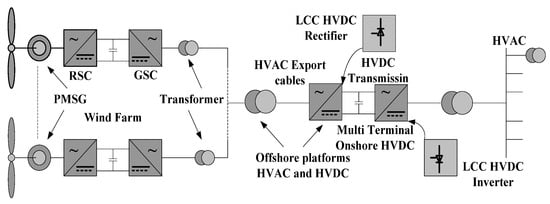
2.2. VSC
2.2. VSC
2.3. Offshore Turbine Converter Topologies
- (1)
-
LCC-based turbine converters or CSC with PWM.
- (2)
-
Interface DC/DC buck between an HVDC system and turbine VSCInterface DC/DC buck between an HVDC system and turbine VSCDC/DC buck interface between the turbine VSC and HVDC system.
3. VSC-HVDC vs. LCC-HVDC
Current-source converters (CSCs), as well known as the LCC-utilizing thyristor, and VSC HVDC, using IGBT transistors, are now the two main HVDC technologies. Both are suited for a variety of applications. CSC-HVDC technology outperforms conventional AC alternatives in terms of efficiency and power transfer capacity for long-distance, high-capacity TSs. VSC-based HVDC is the preferred technology for power transmission (PT) from OPPs with constrained space because it offers superb reactive and active power regulation capabilities. Mercury-arc valves, a technology predominantly developed in Sweden and Germany during the 1930s, are a component of modern HVDC systems. In the past, there have been commercial uses for an HVDC system between Moscow and Kashira in the Soviet Union in 1951, and a 20 MW, 100 kV link between the island of Gotland and the Swedish mainland [44][74]. Since the 1970s, thyristor valves have only recently been utilized in HVDC applications. The mercury-arc technology has largely overcome its drawbacks. The Eel River Converter Station in Canada became the first LCC-HVDC to be operational in 1972. The IGBT valves used in VSCs provided an upgrade over thyristor valves. The first commercial VSC HVDC connection between the Gotland Islands and mainland Sweden was launched by ABB in 1999. It was made up of underwater cables with a 50 MW rating and an 80 kV rating [45][46][75,76].
4. VSC-Based HVDC Scheme
The IGBT technology is used by VSC. Rainer Marquardt developed this idea in 2003 [47][77]. In the event of a black start, it generates its AC voltages, enabling the current to be turned on and off as necessary regardless of the AC voltage. Its converters use pulse width modulation, which allows for simultaneous amplitude and phase angle modification while maintaining a constant voltage. Due to its high level of flexibility and inherent capacity to adjust both its reactive and active power, it is more beneficial in locations with metropolitan power networks. The majority of converter stations for the VSC-HVDC technology employ multilayer converter circuits [48][49][78,79], as seen in Figure 48 and Figure 59 [50][80]. Figure 48.Design of a VSC-HVDC system.
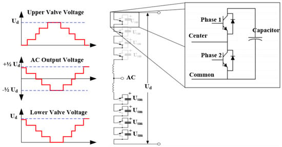 Figure 59.Modular multilevel converter.
VSC-Based HVDC for OWFs
One of the solutions to the problem of fulfilling rising urban and industrial demands is offshore wind energy systems [23][51][52][42,81,82]. OWFs can generate more power and operate more consistently than land-based systems because they have more consistent characteristics and stronger winds than on land [53][83]. Larger wind tribunes are brought on by the viability of OWFs, but the complexity of maintenance and high installation costs present challenges to reducing O&M expenses [53][54][55][83,84,85]. With growing distances from the shore, wind turbine technology is facing additional difficulties like long-distance HVDC undersea cables and the security of turbine equipment [56][86].5. MT-HVDC Transmission Systems
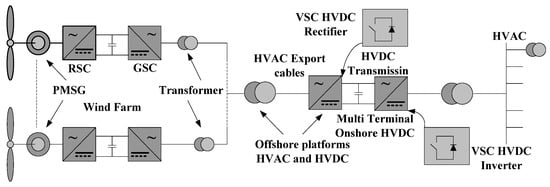
Several converters are coupled to a single HVDC circuit to form a VSC-based MT-HVDC system [57][87]. Squirrel cage induction generators (SCIGs) [58][88] are examples of central power converters used for a group of WTs, while double-fed induction generator (DFIG) WFs use individual power converters in each WT [59][60][89,90]. The so-called WF rectifiers are used to link WFs to the shared HVDC circuit. Through grid-side inverters, the HVDC circuit power is introduced into the terrestrial AC grid [61][91]. The MT DC system’s single-line diagram is depicted in Figure 610. The system includes two grid-side VSCs (GSVSC) and four terminals with wind farm VSCs (WFVSC). The suggested MT DC system, however, can be used with any quantity of terminals and any mix of GSVSCs and WFVSCs. Although other WT technologies, such as those based on the PMG, can also be employed, the two wind farms that are being discussed here are all based on DFIGs and separated from one another. The four terminals are connected at a single point in Figure 711, but other connection patterns are equally applicable.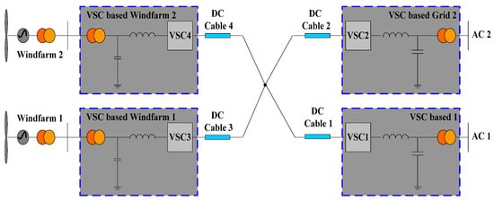 Figure 610.MT VSC HVDC system integration with a single-line diagram.
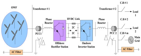 Figure 711.OWPP grid integration schematic using VSC HVDC.Energy from the WFs is gathered and converted to DC by the WF VSCs. DC wires are then used to deliver the DC power to the GSVSCs. The two WFVSCs also regulate the respective wind farm networks’ AC voltages and frequencies. According to a predetermined arrangement, the two GSVSCs convert the DC power back to the respective AC grid.
6. Economic Assessment of HVDC OWFs
The objective of the calculation of cost is to evaluate the capital expenditure (CAPEX) for the configurations under investigation. OWFs are made up of a sizable number of parts. Only the major cost drivers are taken into account when estimating CAPEX. These are the onshore substation, the collection cables, the offshore substation with transformers and switchgear, the high-power converters (HPEs), the export cables, and the wind turbines, including the drive train and foundation. Reactive compensation is necessary for all AC wind farms, and expenses also included are any extra platforms and shunt reactors. All cost data must be normalized because they are accessible for multiple years and are provided in different currencies. The usual interchange rate from the beginning of the year, as acquired from the cost data, is used to convert currencies.6.1. Operational Costs
Based on the indicated median values, the yearly operational cost (OPEX) of every component was calculated as a percentage of the CAPEX. The net present value of the OPEX is obtained by applying the equation to discount the yearly OPEX over the lifetime of the wind farm (WF) [62][100].where On is the yearly OPEX of component n,d is the concession rate, LT is the lifetime in existence, and OpexNPV is the net present value of the operational costs. A concession charge of 6% and a lifespan of 324.222 months are taken into account in the basic scenario [62][63][100,101].6.2. VSC-Based HVDC Transmission Cost Calculation
Regarding VSC-based HVDC transmission, the calculation performed to gain an idea of the overall cost of KVSC consists of Kcap(VSC) for capital expenditures, Kopex(VSC) for operation and maintenance, and Kloss(VSC) for less cost [63][101].
6.2.1. Capital Costs
Kcap(VSC) is made up of two costs: Kstation(VSC) for the foundation of the converter station and Kcable(VSC).
6.2.2. Operation and Maintenance Costs
Equation (3), which is used in the study, yields the Kopex(VSC); the B of the DC submarine cable equals 0.5%, I is 5%, and n is 240 months.6.2.3. Cost of Losses
The converter station loss Ksub(loss) and line loss Kline(loss) make up the loss expenses for the Kloss(VSC) loss rate for converter stations. Psub loss measures how much of the transmitted power is lost at the station. Two converter stations’ Psub(loss) ranges from 1.6 to 2.4%, and Zhen notes that Psub(loss) is between 1 and 2 percent [64][102].6.2.4. Foundation Costs for Converter Stations
The entire infrastructure investment for each converter station is the VSC-based converter station cost. In addition, the expected additional expenses for IGBT technology are the converter station layout’s civil construction costs, the converter station’s DC capacitor and AC filter costs, and the converter station’s converter controller and reactor costs. The cost of a converter station based on VSC is then calculated as a percentage of the capacity of each converter station, denoted by P.
6.2.5. Cost of Cable Installation and Foundation
The DC cable’s VSC-based cost is determined by transmission distance, much like the cost for the HVAC cable is. where P1 and P2 represent the cost and installation expenses for a DC cable per kilometer [19][17]. Since the DC voltage waveform is not susceptible to peak/effective ratio underutilization, the cost of the cables in the VSC-HVDC option is significantly lower than that of AC alternatives. The transmission capability ratio of DC cables to AC cables can be calculated using Equation (6).
 As observed in (6), DC solutions only require two polar wires for a given power transmission, but AC solutions require three. Compared to AC choices, the cost of the cable would be substantially lower with VSC-HVDC. This benefit might be more apparent if the reactive power and skin impact are factored, as in the work of Xiang [65][103].
6.3. An Economic Comparison of HVAC and HVDC Systems
Since every project has unique situations and features, including line distance, rated power, topography, and utilized technology, it is challenging to estimate the accurate price of HVDC. On the other hand, a broad estimate can be derived using the information from earlier initiatives. The DC grid interconnection back-to-back plan of Chongqing-Hubei in China was the first clarified VSC HVDC line, encompassing a total distance of 1711 km with a maximum voltage capability of 420,000 V and a main power transmission capacity of 5000×106 W [66][104]. Three cost factors come into play when comparing HVAC and HVDC economically:-
Cost of line;
-
Cost of losses;
-
Cost of terminal.
 By combining Equations (9) and (10) we obtain Equation (11).
If three-phase AC is substituted with DC, the same power transfer, conductor size, and power loss are assumed [69][70][24,111].
By combining Equations (9) and (10) we obtain Equation (11).
If three-phase AC is substituted with DC, the same power transfer, conductor size, and power loss are assumed [69][70][24,111].
7. Summary
Offshore wind farms must comply with safety limits to ensure the stable operation of the system. The IEC and IEEE have established standards for the integration of offshore wind farms into electrical power systems. These standards cover a range of topics including design, installation, operation, and maintenance of OWFs. Additionally, the safe distance between WTs and the coast, shipping lanes, and other infrastructure are considered in the design process. Some specific safety and performance standards for offshore wind farms include: