 +1 credit
| Version | Summary | Created by | Modification | Content Size | Created at | Operation |
|---|---|---|---|---|---|---|
| 1 | Vlastimil Matejec | -- | 6239 | 2023-10-12 12:44:59 | | | |
| 2 | Camila Xu | Meta information modification | 6239 | 2023-10-13 03:33:05 | | |
Video Upload Options
Recently, rapid progress has been achieved in the field of nanomaterial preparation and investigation. Many nanomaterials have been employed in optical chemical sensors and biosensors. This entry is focused on fiber-optic nanotip sensors for chemical sensing based on silica and plastic optical fibers. The preparation, materials, and sensing characteristics of selected fiber-optic nanotip sensors are employed to show the performance of such nanosensors for chemical sensing. Some examples of fiber-optic nanotip biosensors are included in order to document the broad sensing performance of fiber-optic nanosensors. The employments of fiber nanotips for surface-enhanced Raman scattering, and in nanosensors using both electrical and optical principles are also discussed.
1. Introduction
2. Fiber-Optic Nanotip Sensors
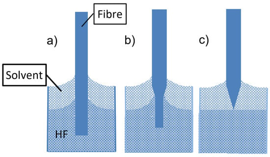
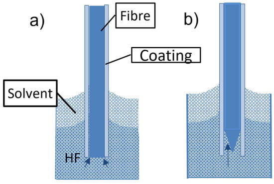
2.1. Fiber Nanotip Preparation
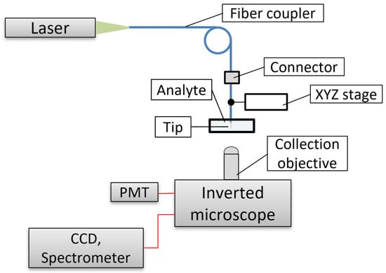
2.2. Fiber Nanotip Sensor Functionalization and Interrogation
2.3. Fiber Nanotip Chemical Sensors
| Analyte | Transducer | Tip Apex Diameter [nm] | Polymer | Reference |
|---|---|---|---|---|
| pH | Fluoresceinamine derivative | 100 | polyacrylamide | [35][56] |
| Ca2+ | Calcium green-dextran | 100 | - | [59] |
| Oxygen | Ru complex 1 | 100 | polyacrylamide | [62] |
| pH | BTB-Ru complex 1 | 50 and 300 | polyHEMA | [53] |
| Cl− | Cl− carrier-CTAB and Chromoionophore 1 |
50 and 300 | PVC | [53] |
| Cl− | Indium porphyrine and chromoionophore 2 |
300–700 | PVC | [60] |
| NO2− | vitamin B12 derivative and chromoionophore 3 |
300–700 | PVC | [60] |
| K+ | Valinomycin and chromoionophore 4 | 50 and 300 | PVC copolymer | [54] |
| RI | - | 50 | - | [55] |
2.4. Fiber Nanotip Biosensors
2.5. Fiber-Optic Nanotip Sensors for Raman Spectroscopy
2.6. Fiber-Optic Nanotips for Electro-Optical Detection
3. Conclusions
This contribution deals with fiber nanotip sensors for chemical sensing based on silica or plastic optical fibers. The contribution shows the fabrication of such sensors, their material characteristics, and their sensing performance for chemical detection in gases, solutions, cells, bacteria, pores, etc. Examples of biosensors employing such nanosensors are also reported in order to document their broad sensing performance.
Fiber nanotip sensors can employ commercially available SNOM nanotips, or they can be prepared by thermal pulling or chemical etching. While the thermal pulling requires a sophisticated device, the etching can be realized in a chemical laboratory provided that safety rules for working with hydrofluoric acid are kept. However, nanotips prepared by chemical etching need to be metalized to preserve their mechanical stability. On the other hand, SNOM nanotips are metalized. Nanotips with apex diameters bellow 100 nm can be employed for intracellular measurements. However, in this field, they will compete with PEBBLES (probes embedded in biologically localized environments). Thus fiber-optic nanotip and microtip sensors can be useful for chemical detection in pores, cell tissues, and small drops. Chemical sensing in plant tissues and drops of exudates from plants is possible with fiber microtip sensors[80] and can provide us with information on chemical mechanisms in plant tissues, leaves, etc. Information about concentrations of chemicals in material pores can be employed for investigations of solid catalysts, metal corrosion, etc. One can also expect that fiber-optic microtips and nanotips will be employed for the development of optical tweezers and coupling devices. Fiber nanotips coated with metallic nanoparticles or nanoislands exhibit a very good performance for SERS-based chemical analysis which still is not fully employed.
References
- Wolfbeis, O.S. Fiber-Optic Chemical Sensors and Biosensors. Anal. Chem. 2002, 74, 2662–2678.
- Wolfbeis, O.S. Fiber-Optic Chemical Sensors and Biosensors. Anal. Chem. 2004, 76, 3269–3284.
- Wolfbeis, O.S. Fiber-Optic Chemical Sensors and Biosensors. Anal. Chem. 2006, 78, 3859–3874.
- Wolfbeis, O.S. Fiber-Optic Chemical Sensors and Biosensors. Anal. Chem. 2008, 80, 4269–4283.
- Wang, X.-D.; Wolfbeis, O.S. Fiber-Optic Chemical Sensors and Biosensors (2008−2012). Anal. Chem. 2013, 85, 487–508.
- Wang, X.-D.; Wolfbeis, O.S. Fiber-Optic Chemical Sensors and Biosensors (2013−2015). Anal. Chem. 2016, 88, 203–227.
- Wang, X.-D.; Wolfbeis, O.S. Fiber-Optic Chemical Sensors and Biosensors (2015−2019). Anal. Chem. 2020, 92, 397–430.
- Borisov, S.M.; Wolfbeis, O.S. Optical Biosensors. Anal. Chem. 2008, 108, 423–461.
- Abdelmalek, F.; Lacroix, M.; Chovelon, J.M.; Jaffrezic-Renault, N.; Berkova, D.; Matejec, V.; Kasik, I.; Chomat, M.; Gagnaire, H. Consequences of TiO2 doping on the optical properties of porous silica layers coated on silica optical fibers. Thin Sol. Film. 1999, 340, 280–287.
- Skokankova, J.; Mrazek, J.; Matejec, V.; Hayer, M.; Kasik, I.; Chomat, M.; Berkova, D.; Barau, A.; Zaharescu, M.; Raileanu, M. Properties of xerogel layers for the detection of toluene in water. Mater. Sci. Eng. C 2006, 26, 208–213.
- Abdelghani, A. Jaffrezic-Renault, N. SPR fibre sensor sensitised by fluorosiloxane polymers. Sens. Actuators B-Chem. 2001, 74, 117–123.
- Snyder, A.W.; Love, J.D. Optical Waveguide Theory. Part II Electromagnetic Analysis of Optical Waveguides; Springer: New York, NY, USA, 1983; pp. 203–353.
- Monro, T.M.; Belardi, W.; Furusawa, K.; Baggett, J.C.; Broderick, N.G.R.; Richardson, D.J. Sensing with microstructured optical fibres. Meas. Sci. Technol. 2001, 12, 854–858.
- Matejec, V.; Mrázek, J.; Hayer, M.; Podrazký, O.; Kaňka, J.; Kašík, I. Sensitivity of microstructure fibers to gaseous oxygen. Meas. Sci. Eng. 2008, 28, 876–881.
- Elsherif, M.; Salih, A.E.; Gutiérrez Munoz, M.; Alam, F.; AlQattan, B.; Antonysamy, D.S.; Fawzi Zaki, M.; KYetisen, A.; Park, S.; Wilkinson, T.D.; et al. Optical Fiber Sensors: Working Principle, Applications, and Limitations. Adv. Photonics Res. 2022, 3, 2100371.
- Gupta, B.D.; Kant, R. Recent advances in surface plasmon resonance based fiber optic chemical and biosensors utilizing bulk and nanostructures. Opt. Laser Technol. 2018, 101, 144–161.
- Li, M.; Singh, R.; Wang, Y.; Marques, C.; Zhang, B.; Kumar, S. Advances in Novel Nanomaterial-Based Optical Fiber Biosensors—A Review. Biosensors 2022, 12, 843.
- Boussard-Plédel, C. Chalcogenide waveguides for infrared sensing. In Chalcogenide Glasses: Preparation, Properties and Applications; Adam, J.-L., Zhang, X., Eds.; Woodhead Publishing Series in Electronic and Optical Materials; Woodhead Publishing Limited: Oxford, UK; Cambridge, UK; London, UK; Philadelphia, PA, USA; New Delhi, India, 2014; Volume 44, pp. 381–410.
- Bureau, B.; Boussard, C.; Cui, S.; Chahal, R.; Laure Anne, M.; Nazabal, V.; Sire, O.; Loréal, O.; Lucas, P.; Monbet, V.; et al. Chalcogenide optical fibers for midinfrared sensing. Opt. Eng. 2014, 53, 027101.
- Matějec, V.; Chomát, M.; Hayer, M.; Kašik, I.; Berková, D. Development of special optical fibers for evanescent-wave chemical sensing. Czech. J. Phys. 1999, 49, 883–888.
- Wu, W.; Huang, J.; Ding, L.; Lin, H.; Yu, S.; Yuan, F.; Liang, B. A real-time and highly sensitive fiber optic biosensor based on the carbon quantum dots for nitric oxide detection. J. Photochem. Photobiol. A 2021, 405, 112963.
- Ding, L.; Fan, C.; Zhong, Y.; Li, T.; Huang, J. A sensitive optic fiber sensor based on CdSe QDs fluorophore for nitric oxide detection. Sens. Actuators B-Chem. 2013, 185, 70–76.
- Ding, L.Y.; Ruan, Y.L.; Li, T.; Huang, J.; Warren-Smith, S.C.; Ebendorff-Heidepriem, H.; Monro, T.M. Nitric oxide optical fiber sensor based on exposed core fibers and CdTe/CdS quantum dots. Sens. Actuators B-Chem. 2018, 273, 9–17.
- Pathak, A.; Gupta, B.D. Fiber-Optic Plasmonic Sensor Utilizing CTAB-Functionalized ZnO Nanoparticle-Decorated Carbon Nanotubes on Silver Films for the Detection of Catechol in Wastewater. ACS Appl. Nano Mater. 2020, 3, 2582–2593.
- Fallah, H.; Asadishad, T.; Parsanasab, G.-M.; Harun, S.W.; Mohammed, W.S.; Yasin, M. Optical Fiber Biosensor toward E-coli Bacterial Detection on the Pollutant Water. Eng. J. 2021, 25, 1–8.
- Sun, Y.; Guo, X.; Moreno, Y.; Sun, Q.; Yan, Z.; Zhang, L. Sensitivity adjustable biosensor based on graphene oxide coated excessively tilted fiber grating. Sens. Actuators B-Chem. 2022, 351, 130832.
- Wang, R.; Ren, Z.; Kong, D.; Hu, B.; He, Z. Highly sensitive label-free biosensor based on graphene-oxide functionalized micro-tapered long period fiber grating. Opt. Mater. 2020, 109, 110253.
- Cao, Z.; Yao, B.; Qin, C.; Yang, R.; Guo, Y.; Zhang, Y.; Wu, Y.; Bi, L.; Chen, Y.; Xie, Z.; et al. Biochemical sensing in graphene enhanced microfiber resonators with individual molecule sensitivity and selectivity. Light Sci. Appl. 2019, 8, 107.
- Yu, H.; Chong, Y.; Zhang, P.; Ma, J.; Li, D. A D-shaped fiber SPR sensor with a composite nanostructure of MoS2-graphene for glucose detection. Talanta 2020, 219, 121324.
- Li, W.; Miao, Y.; Guo, T.; Zhang, K.; Yao, J. Nb2CTx MXene-tilted fiber Bragg grating optofluidic system based on photothermal spectroscopy for pesticide detection. Biomed. Opt. Express 2021, 12, 7051–7063.
- Yi, D.; Wang, C.; Gao, L.; Chen, Y.; Liu, F.; Geng, Y.; Zhang, H.; Li, X. Ti3CN MXene-based ultra-sensitive optical fiber salinity sensor. Opt. Lett. 2022, 47, 138–141.
- Baig, N.; Kammakakam, I.; Falathabe, W. Nanomaterials: A review of synthesis methods, properties, recent progress, and challenges. Mater. Adv. 2021, 2, 1821–1871.
- Berneschi, S.; Barucci, A.; Baldini, F.; Cosi, F.; Quercioli, F.; Pelli, S.; Righini, G.C.; Tiribilli, B.; Tombelli, S.; Trono, C.; et al. Optical Fibre Micro/Nano Tips as Fluorescence-Based Sensors and Interrogation Probes. Optics 2020, 1, 213–242.
- Betzig, E.; Trautman, J.K.; Harris, T.D.; Weiner, J.S.; Kostelak, R.L. Breaking the Diffraction Barrier: Optical Microscopy on a Nanometric Scale. Science 1991, 251, 1468–1470.
- Tan, W.; Shi, Z.-Y.; Smith, S.; Birnbaum, D.; Raoul Kopelman, R. Submicrometer Intracellular Chemical Optical Fiber Sensor. Science 1992, 258, 778–781.
- Lewis, A.; Lieberman, K. The optical Near Field and Analytical Chemistry. Anal. Chem. 1991, 63, 625A–638A.
- Lee, S.; Jiao, M.; Zhang, Z.; Yu, Y. Nanoparticles for Interrogation of Cell Signaling. Annu. Rev. Anal. Chem. 2023, 16, 333–351.
- Clark, H.A.; Hoyer, M.; Philbert, M.A.; Kopelman, R. Optical Nanosensors for Chemical Analysis inside Single Living Cells. 1. Fabrication, Characterization, and Methods for Intracellular Delivery of PEBBLE Sensors. Anal. Chem. 1999, 71, 4831–4836.
- Clark, H.A.; Kopelman, R.; Tjalkens, R.; Philbert, M.A. Optical Nanosensors for Chemical Analysis inside Single Living Cells. 2. Sensors for pH and Calcium and the Intracellular Application of PEBBLE. Anal. Chem. 1999, 71, 4837–4843.
- Kopelman, R.; Smith, S.; Tan, W.; Zenobi, R.; Lieberman, K.; Lewis, A. Spectral analysis of surfaces at subwavelength resolution, Proc. SPIE Environ. Process Monit. Technol. 1992, 1637, 33–40.
- Paiva, J.S.; Jorge, P.A.S.; Rosa, C.C.; Cunha, J.P.S. Optical fiber tips for biological applications: From light confinement, biosensing to bioparticles manipulation—Review. Biochim. Biophys. Acta (BBA)-General. Subj. 2018, 1862, 1209–1246.
- Valaskovic, G.A.; Holton, M.; Morrison, G.H. Parameter control, characterization, and optimization in the fabrication of optical fiber near-field probes. Appl. Opt. 1995, 34, 1215–1228.
- Turner, D.R. Etch Procedure for Optical Fibers. US Patent 4,469,554, 4 September 1984.
- Hoffmann, P.; Dutoit, B.; Salathe, R.-P. Comparison of mechanically drawn and protection layer chemically etched optical fiber tips. Ultramicroscopy 1995, 61, 165–170.
- Anderson, G.P.; Golden, J.P.; Ligler, F.S. A fiber tapered optic biosensor: Combination fibers designed for improved signal acquisition. Biosens. Bioelectr. 1993, 8, 249–256.
- Muramatsu, H.; Homma, K.; Chiba, N.; Yamamoto, N.; Egawa, A. Dynamic etching method for fabricating a variety of tip shapes in the optical fibre probe of a scanning near-field optical microscope. J. Microscop. 1999, 194, 383–387.
- Lazarev, A.; Fang, N.; Luo, Q.; Zhang, X. Formation of fine near-field scanning optical microscopy tips. Part I. Rev. Sci. Instrum. 2003, 74, 3679–3683.
- Giannetti, A.; Barucci, A.; Cosi, F.; Pelli, S.; Tombelli, S.; Trono, C.; Baldini, F. Optical fiber nanotips coated with molecular beacons for DNA detection. Sensors 2015, 15, 9666–9680.
- Griffini, D.; Insinna, M.; Salvadori, S.; Barucci, A.; Cosi, F.; Pelli, S.; Righini, G.C. On the CFD analysis of a stratified taylor-couette system dedicated to the fabrication of nanosensors. Fluids 2017, 2, 8.
- Lambelet, P.; Sayah, A.; Pfeffer, M.; Philipona, C.; Marquis-Weible, F. Chemically etched fiber tips for near-fieldoptical microscopy: A process for smoother tips. Appl. Opt. 1998, 37, 7289–7292.
- Stὅckle, R.; Fokas, C.; Deckert, V.; Zenobia, R.; Sick, B.; Hecht, B.; Wild, U.P. High-quality near-field optical probes by tube etching. Appl. Phys. 1999, 75, 160–162.
- Pangaribuana, T.; Jiang, S.; Ohtsu, M. Highly Controllable Fabrication of Fiber Probe for Photon Scanning Tunneling. Scanning 1994, 16, 362–367.
- Koronczi, I.; Reichert, J.; Ache, H.J.; Krause, C.; Werner, T.; Wolfbeis, O.S. Submicron sensors for ion detection based on measurement of luminescence decay time. Sens. Actuators B-Chem. 2001, 74, 47–53.
- Koronczi, I.; Reichert, J.; Heinzmann, G.; Ache, H.J. Development of a submicron optochemical potassium sensor with enhanced stability due to internal reference. Sens. Actuators B-Chem. 1998, 51, 188–195.
- Tai, Y.-H.; Wei, P.-K. Sensitive liquid refractive index sensors using tapered optical fiber tips. Opt. Lett. 2010, 35, 944–946.
- Tan, W.; Shi, Z.Y.; Kopelman, R. Development of submicron chemical fiber optic sensors. Anal. Chem. 1992, 64, 2985–2990.
- Munkholm, C.; Walt, D.R.; Milanovich, F.P.; Klainer, S.M. Polymer Modification of Fiber Optic Chemical Sensors as a Method of Enhancing Fluorescence Signal for pH Measurement. Anal. Chem. 1986, 58, 1427–1430.
- Vo-Dinh, T.; Kasili, P.; Wabuyele, M. Nanoprobes and nanobiosensors for monitoring, and imaging individual living cells. Nanomed. Nanotechnol. Biol. Medic. 2006, 2, 22–30.
- Wanga, S.; Ye, F.; Lang, X.; Fei, D.; Ge, Y.; Turner, A.P.F. Detection of changes in sub-plasma membrane microdomains in a single living cell by an optical fiber-based nanobiosensor. Austin J. Nanomed. Nanotechnol. 2014, 2, 1022.
- Barker, S.L.R.; Bjorn, A.; Thorsrud, B.A.; Kopelman, R. Nitrite- and Chloride-Selective Fluorescent Nano-Optodes and in Vitro Application to Rat Conceptuses. Anal. Chem. 1998, 70, 100–104.
- Tan, W.; Shi, Z.-Y.; Kopelman, R. Miniaturized fiber-optic chemical sensors with fluorescent dye-doped polymers. Sens. Actuators B-Chem. 1995, 28, 157–165.
- Rosenzweig, Z.; Kopelman, R. Development of a submicrometer optical fiber oxygen sensor. Anal. Chem. 1995, 67, 2650–2654.
- Tan, W.; Kopelman, R.; Barker, S.L.R.; Miller, M.T. Peer Reviewed: Ultrasmall Optical Sensors for Cellular Measurements. Anal. Chem. 1999, 71, 606A–612A.
- Hossein-Zadeha, M.; Delgado, J.; Schweizer, F.; Lieberman, R. Sub-micron Opto-Chemical Probes for Studying Living Neurons. In Proceedings of the SPIE 10051, Neural Imaging and Sensing, San Francisco, CA, USA, 8 February 2017. 100510G; paper 100510G(9pp).
- Bui, J.D.; Zelles, T.; Lou, H.J.; Gallion, V.L.; Phillips, M.I.; Tan, W. Probing intracellular dynamics in living cells with near-field optics. J. Neurosc. Methods 1999, 89, 9–15.
- Vo-Dinh, T.; Kasili, P. Fiber-optic nanosensors for single-cell monitoring-Review. Anal. Bioanal. Chem. 2005, 382, 918–925.
- Alarie, J.P.; Vo-Dinh, T. Antibody-Based Submicron Biosensor for BenzoPyrene DNA Adduct. Polycycl. Arom. Compd. 1996, 8, 45–52.
- Cullum, B.M.; Griffin, G.D.; Miller, G.H.; Vo-Dinh, T. Intracellular Measurements in Mammary Carcinoma Cells Using Fiber-Optic Nanosensors. Anal. Biochem. 2000, 277, 25–32.
- Kasili, P.M.; Song, J.M.; Vo-Dinh, T. Optical Sensor for the Detection of Caspase-9 Activity in a Single Cell. J. Am. Chem. Soc. 2004, 126, 2799–2806.
- Barker, S.L.R.; Kopelman, R. Development and Cellular Applications of Fiber Optic Nitric Oxide Sensors Based on a Gold-Adsorbed Fluorophore. Anal. Chem. 1998, 70, 4902–4906.
- Cordek, J.; Wang, X.; Tan, W. Direct Immobilization of Glutamate Dehydrogenase on Optical Fiber Probes for Ultrasensitive Glutamate Detection. Anal. Chem. 1999, 71, 1529–1533.
- Song, J.M.; Kasili, P.M.; Griffin, G.D.; Vo-Dinh, T. Detection of Cytochrome c in a Single Cell Using an Optical Nanobiosensor. Anal. Chem. 2004, 76, 2591–2594.
- Petry, R.; Schmitt, M.; Popp, J. Raman spectroscopy—A prospective tool in the Life Sciences. Chem. Phys. Chem. 2003, 4, 14–30.
- Jonathan, P.; Scaffidi, J.P.; Gregas, M.K.; Seewaldt, V.; Vo-Dinh, T. SERS-based plasmonic nanobiosensing in single living cells. Anal. Bioanal. Chem. 2009, 393, 1135–1141.
- Chen, Z.; Dai, Z.; Chen, N.; Liu, S.; Pang, F.; Lu, B.; Wang, T. Gold Nanoparticles-Modified Tapered Fiber Nanoprobe for Remote SERS Detection. IEEE Phot. Technol. Lett. 2014, 26, 777–780.
- Lucotti, A.; Zerbi, G. Fiber-optic SERS sensor with optimized geometry. Sens. Actuators B-Chem. 2007, 121, 356–364.
- Wang, J.; Geng, Y.; Shen, Y.; Shib, W.; Xu, W.; Xu, S. SERS-active fiber tip for intracellular and extracellular pH sensing in living single cells. Sens. Actuators B-Chem. 2019, 290, 527–534.
- Hutter, T.; Elliot, S.R.; Mahajan, S. Optical fibre-tip probes for SERS: Numerical study for design considerations. Opt. Express 2018, 26, 15539–15550.
- Zheng, X.T.; Hua, W.; Wang, H.; Yang, H.; Zhoud, W.; Li, C.M. Bifunctional electro-optical nanoprobe to real-time detect local biochemical processes in single cells. Biosens. Bioelectron. 2011, 26, 4484–4490.
- Kasik, I., Mrazek, J., Martan, T., Pospisilova. M.., Podrazky, O., Matejec, V., Hoyerova, K., Kaminek, M. Fiber-optic pH detection in small volumes of biosamples. Anal. Bioanal. Chem. 2010, 398, 1883–1889.

