Recently, rapid progress has been achieved in the field of nanomaterial preparation and investigation. Many nanomaterials have been employed in optical chemical sensors and biosensors. This entry is focused on fiber-optic nanotip sensors for chemical sensing based on silica and plastic optical fibers. The preparation, materials, and sensing characteristics of selected fiber-optic nanotip sensors are employed to show the performance of such nanosensors for chemical sensing. Some examples of fiber-optic nanotip biosensors are included in order to document the broad sensing performance of fiber-optic nanosensors. The employments of fiber nanotips for surface-enhanced Raman scattering, and in nanosensors using both electrical and optical principles are also discussed.
- nanosensor
- fiber nanotip
- chemical sensing
- preparation
- characteristics
1. Introduction
2. Fiber-Optic Nanotip Sensors
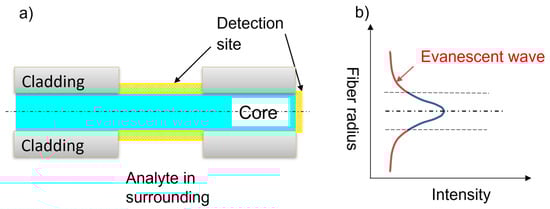
Optical, chemical nanosensors and nanobiosensors based on fiber-optic (FO) nanotips can provide with reliable methods for monitoring chemicals in microscopic samples and detecting chemicals within single cells [33]. FO nanotip sensors offer significant improvements over methods of cellular analysis, such as direct loading of cells with fluorescent indicators. These nanosensors exhibit several useful characteristics for cellular analysis. They are biocompatible and can protect the intracellular environment from the effects of dyes injected during direct loading. Their nanometer sizes minimize physical perturbation of the cell, and their small size can provide a fast response time for the sensor. Opto-chemical transducers are immobilized on nanosensor surfaces and do not suffer from diffusion in the cell. The first papers on FO nanotips and nanotip sensors were published around 1990 [34][35][36]. Papers on the development of such sensors can be found approximately until 2010. Since then, the number of articles has decreased. This decrease may be related to the broad use of luminescence nanoparticles (probes embedded in localized environment, PEBBLEs) [37][38][39]. Such nanoparticles have been employed intensively for intercellular chemical analysis [37][38][39]. They can be fabricated by well-elaborated chemical methods, which are probably less complicated than techniques used for the fabrication of FO nanotips. However, their insertion into cells is more complicated than that of FO nanotips. They can also require sophisticated optical instruments for their interrogations. A fiber-optic nanotip is represented by an optical fiber element with one end elongated into a sharp tip with an apex. In this paper, fiber tips with apex diameters in a range of 20–100 nm are considered nanotips. However, in some papers, this term is also used for fiber tips with apex diameters below one micrometer. The term submicrometer tips used in some papers seems more suitable for tips with apex diameters from 100 to 1000 nm. In some papers, published results are not related to precise information on the tip apex diameters. Transducers are usually immobilized in detection sites on the tip apex. Nanometer dimensions of the apex mean that all optical changes in the site take place in the near- field of EM waves transmitted through the site. In fact, FO nanotips have successfully been employed for scanning near-field optical microscopy (SNOM) [40].2.1. Fiber Nanotip Preparation
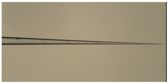
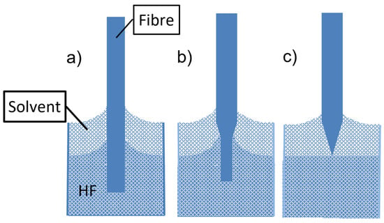
To prepare fiber-optic nanotips, different methods have been employed. They include high-resolution micromachining, focused ion beam milling (FIB), femtosecond laser machining, lithography, photopolymerization, thermal pulling, and chemical etching. The principles and performance of such techniques have been reviewed elsewhere [33][41]. FIB, lithography, femtosecond laser machining, and high-resolution micromachining require complex and costly devices. The technique based on grinding and polishing is simple and low-cost. However, it is more suitable for the preparation of fiber microtips [41]. High-resolution micromachining has been used only for the fabrication of nanoarrays on the end of a single fiber and not for the preparation of fiber nanotips [41]. Photopolymerization has been employed for the application of sensing nanomembranes on fiber tips but not for tip preparation. Thus, thermal pulling and chemical etching are discussed in detail in this paper. The thermal pulling technique is schematically described in Figure 3. The technique uses a heat source, gas torch, or CO2 laser that heats a bare part of a fiber element while tension is applied along the major axis of the element. The fiber is fixed in clamps so the applied tension can be controlled. By heating silica glass fibers at temperatures above 1600 °C, viscous flows in glass are induced. These flows and the glass surface tension, together with the applied external tensions, cause a decrease in the diameter of the bare fiber part and fiber elongation. A biconical taper is produced at first (see Figure 3b). This taper has a short central part, the waist, with a constant diameter. By continuing the heating, the taper is broken, and two fiber tips are produced (see Figure 3c). By controlling the heating temperature, the tensions applied to the element, and the heating duration, fiber tips with minimum apex diameters of approximately 20 nm can be fabricated by this technique [42]. The thermal pulling process is rapid (~3 s) and produces smooth tips. It is not very reproducible with respect to tip apex diameters and taper cones. It can be realized on a commercially available micropipette puller, which is relatively expensive. An example of a fiber tip produced by the thermal pulling of a silica fiber with an outer diameter of 125 µm to a microtip taper of 0.6 µm in diameter is shown in Figure 4. Such tapers have been fabricated at the author’s laboratories on a laboratory thermal-pulling device.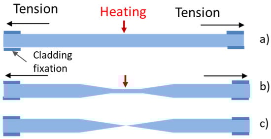
2.2. Fiber Nanotip Sensor Functionalization and Interrogation
The research of fiber nanotip–chemical sensors and biosensors was mainly developed from 1992 to roughly 2010. After the first paper on fiber nanotip pH sensors was published in 1992 [35], a series of papers on chemical sensors and biosensors based on fiber nanotips followed. Fiber nanotips prepared from telecommunication types of optical fiber by thermal pulling or chemical etching can be employed, as well as commercially available SNOM fibers which are provided by metal coatings [40]. In order to employ fiber nanotips for chemical sensing and biosensing, they must be modified with proper sensing membranes and/or opto-chemical transducers or biotransducers. For such modifications, fiber nanotip surfaces are functionalized by silanization. Silanization provides with chemical groups, making strong bonding of membranes and transducers onto tip surfaces possible. Other functionalization approaches, such as surface-assembled monolayers (SAM) [8], have not been applied to the development of fiber nanotip sensors. As sensing membranes for fiber nanotip chemical sensors, photocurable or thermally curable polymers were employed [35][56]. Such membranes immobilize chemical transducers onto fiber tips. Biotransducers are immobilized onto fiber tips by interacting with the silanized tip surface. When using photocuring, a silanized fiber nanotip is dipped into the proper monomer, and curing radiation (e.g., from a 488 nm-Ar laser) is launched into the proximal fiber face. Radiation is guided in the fiber core to the nanotip apex, where photopolymerization occurs near the optical field. A small cone with dimensions comparable to the apex diameter is formed on the apex [57]. Polymers such as acrylates, poly vinyl chloride, and dextran can be used for the fabrication of sensing membranes on fiber nanotips. In the case of thermal curing, a fiber nanotip is immersed in a proper monomer that is subsequently thermally cured. However, this thermal curing usually requires a catalyst and the control of the thickness of the sensing membrane is difficult. It is produced anywhere on the immersed fiber. Changes in luminescence, usually fluorescence, taking place when a fiber nanotip sensor is in contact with detected chemicals, are usually used in fiber nanotip sensors. Because of small sample volumes in contact with sensing nanotips on the order of femtoliters [35], the number of analyte molecules in the excitation volume is also small on the order of several thousands of molecules. Therefore, sensitive devices capable of measuring weak fluorescence signals must be used for analysis. A principal set-up used for measuring with fiber nanotip sensors is schematically shown in Figure 7. A more specific description of such a set-up can be found elsewhere [58]. The main part of the set-up is an inverted fluorescence microscope with a detector such as a photomultiplier tube (PMT) or avalanche photodiode for intensity measurements, a spectrometer for spectra measurements, and/or a CCD camera for target imaging. Dichroic mirrors, filters, and objectives are other parts of the microscope. A fiber nanotip sensor is fixed on a three-way X,Y,Z translational stage, making its precise insertion into a sample possible. Radiation from a laser is launched into the sensor using a fiber coupler. It excites the fluorescence of a transducer immobilized on the sensor nanotip. The emitted fluorescence signal and remaining excitation radiation are collected by the microscope collection objective. The rest of the excitation radiation is filtered out by a notch filter, and fluorescence is detected by PMT or by spectrometer. In this set-up, fluorescence signals emitted in the direction of the tip axis are detected. One can also find another experimental set up used for sensing with fiber-optic nanotip sensors [48]. In the set-up, fluorescence emitted from the sensor nanotip is registered in the direction perpendicular to the tip axis. The fluorescence is collected by a GRIN lens coupled with a multimode optical fiber. The excitation radiation scattered from the tip apex is also filtered out in this set-up.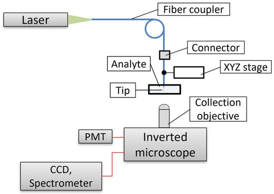
2.3. Fiber Nanotip Chemical Sensors
Fiber nanotip chemical sensors have been tested for the detection of pH, different ions, nitric oxide, etc. Selected examples of such sensors are reported in Table 1. They were developed using fiber-optic tips with apex diameters of 50–700 nm. These tips were fabricated from multimode [53][54][59] and single-mode optical fibers [54][60] using thermal pulling methods or the tube etching technique [54]. Commercially available nanotip fibers (SNOM) were also used [53][54]. Only some of these nanotip fibers were provided with metal layers of aluminum [53][54][60] or silver [59]. Some fiber tips were used without any metal coating [53][54][55]. Fiber nanotip chemical sensors have employed different chemical transducers (see examples in Table 1). In pH, oxygen, and Ca2+ FO nanosensors, simple fluorescence transducers, acryloylfluorescein, Ru(II) phenanthroline complexes, and calcium green-1dextran dye, respectively, were employed. Other dextran-immobilized transducers, such as 2′,7′-bis-(carboxyethyl)-5(6′)-carboxyfluorescein (BCECF) pH transducer, were also employed in fiber nanotip chemical sensors [61].| Analyte | Transducer | Tip Apex Diameter [nm] | Polymer | Reference |
|---|---|---|---|---|
| pH | Fluoresceinamine derivative | 100 | polyacrylamide | [35][56] |
| Ca2+ | Calcium green-dextran | 100 | - | [59] |
| Oxygen | Ru complex 1 | 100 | polyacrylamide | [62] |
| pH | BTB-Ru complex 1 | 50 and 300 | polyHEMA | [53] |
| Cl− | Cl− carrier-CTAB and Chromoionophore 1 |
50 and 300 | PVC | [53] |
| Cl− | Indium porphyrine and chromoionophore 2 |
300–700 | PVC | [60] |
| NO2− | vitamin B12 derivative and chromoionophore 3 |
300–700 | PVC | [60] |
| K+ | Valinomycin and chromoionophore 4 | 50 and 300 | PVC copolymer | [54] |
| RI | - | 50 | - | [55] |
2.4. Fiber Nanotip Biosensors
Fiber-optic nanotips have been successfully employed in optical biosensors. The reader can find reviews on such nanobiosensors elsewhere [33][66]. Several examples of nanobiosensors discussed below can illustrate the performance of fiber-optic nanotips for biosensing, particularly in cells. A fiber nanotip biosensor was reported for the detection of benzo[a]pyrene tetrol (BPT) [67][68]. It is known that BPT is one of the metabolites of benzo[a]pyrene in cells. It can form adducts with DNA which can be related to its carcinogenic effects. BPT has an intrinsic fluorescence that can be employed for its detection. Fiber-optic tips with apex diameters of 25–40 nm were used for sensor fabrications. In the sensor, the tip was functionalized with BPT antibody by covalent binding on the silanized tip. This antibody allows to selectively bind BPT due to immunoreaction. The sensor was excited by a HeCd laser at 325 nm and emitted BPT fluorescence was detected by a detector (PMT). The sensor was characterized on mammary carcinoma cells and rat liver epithelial cells incubated with BPT. These cells are spherical with diameters of approximately 10 µm. A dynamic range of 0.006–1.6 nM and a limit of detection of 0.006 nM were determined from calibration curves [69]. From these curves, an average detection sensitivity of approximately 7000 nM−1 can be estimated. Several other fiber nanotip biosensors have been developed, as can be found in review articles [33][66]. These biosensors include those for the detection of nitric oxide [70], caspase-9 [69], glutamate [71], cytochrome c’ [72], DNA [48], etc. Biotransducers for some fiber nanotip biosensors are shown in Table 2. Caspase-9 was detected using a modified enzymatic assay based on leucine–glutamic acid–histidine–aspartic acid ↔ 7-amino-4-methylcoumarin (LEDH ↔ AMC) that is immobilized on the fiber nanotip [69]. Caspase-9 cleaves nonfluorescent LEDH ↔ AMC and the fluorescence of free AMC is detected in the sensor. Anti-cytochrome c’–biotin immobilized on the sensor nanotip is used to bind cytochrome c’ to the tip [72]. An enzyme-linked immunoassay sorbent is used for the detection of cytochrome c’ bound on this antibody.2.5. Fiber-Optic Nanotip Sensors for Raman Spectroscopy
The sensing performance of fiber nanotip chemical sensors and biosensors can be further enhanced by coating them with metallic nanoparticles or metal islands. Such fiber-optic structures enable to employ surface-enhanced Raman scattering (SERS) for detection. It is well known that Raman spectroscopy allows to investigate molecules, cells, viruses, etc., at molecular, nanoscopic, and microscopic levels [73]. This spectroscopy employs inelastic Raman scattering. Both qualitative and quantitative information can be obtained from Raman spectra. While the qualitative information can be directly determined from the wavelength position of vibrational spectral bands, the quantitative information can be limited by low Raman scattering cross-sections. This limitation can be overcome, and the cross-sections can be highly increased using nano-textured surfaces in SERS sensors. In addition to common nanostructured substrates, electrodes, sols, metal films, and nanomaterial-modified fiber nanotips have also been employed in SERS sensors. Such sensors were fabricated by applying silver and gold nanoparticles or nanoislands on surfaces of tips obtained by chemical etching. For such applications, fiber nanotips were silanized to enhance the binding of metal nano-objects on the surface. Electron beam evaporation [74] and wet chemical synthesis [75][76][77] were employed for the fabrication of such nano-objects. It is known that metal nano-objects (nanoparticles, nanorods, and nanoislands) support the excitation and propagation of localized surface plasmons (LSPs) [16][73]. If an absorption spectrum of LSP overlaps with excitation and emission SERS wavelengths, Raman scattering is highly enhanced. Confocal microscopes [73], inverted fluorescence microscopes [77], and Raman spectrometers were used to measure Raman spectra. A pH sensor based on SERS was developed [74]. The sensor used a tip with an apex diameter below 100 nm that was coated with a silver layer of 6 nm in thickness using electron beam evaporation. The layer with such a small thickness was not continuous, but it was formed of silver islands. As a pH transducer, p-mercaptobenzoic acid (MBA) was bound to these islands. The nanotips were interrogated by confocal microscopy. A spectral band of 1425 cm−1, shifting due to pH changes, was employed in this pH sensor. The sensor was also used for pH measurements in cells. In another paper [75], gold nanoparticles with diameters in the range of 50–60 nm prepared by chemical wet synthesis were applied onto a fiber nanotip with an apex diameter of 40 nm. Such fibers were successfully employed for measuring Raman spectra of Rhodamine 6G in aqueous solutions. The excitation radiation from a 633 nm laser was launched into the proximal fiber face. The excited SERS radiation was detected at the proximal face, too. A remote interrogation scheme was also used for measurements with a fiber nanotip SERS sensor employing silver nanoparticles coated on the tip [76]. A double-tapered fiber tip was prepared by the Turner method. However, there is no specific information regarding the tip dimensions in the current literature. The sensor was used for measuring Raman spectra of solutions of crystal violet at concentrations higher than 1 nM. Silver nanoparticles modified with 4-mercaptopyridine (Mpy) were also used for the development of a SERS fiber nanotip sensor [77]. The modified nanoparticles were coated on a fiber nanotip using laser-induced Ag deposition from silver nitrate and Mpy solution. Nanoparticles with diameters of approximately 100 nm were applied. Such fiber nanotip SERS sensors were used for pH detection. An inverted microscope was used to register SERS radiation from samples that were excited by the tips. Results of theoretical modeling of fiber nanotip SERS sensors based on Au nanoparticles and MBA were reported [78]. It was found that the nanoparticle diameter has a high effect on the electrical-field enhancement between nanoparticles. On the other hand, tip dimensions do not exhibit significant effects on MBA spectra. Based on this modeling, fiber nanotips with an apex diameter of 50 nm coated with gold nanoparticles of 60 nm in diameter were experimentally realized2.6. Fiber-Optic Nanotips for Electro-Optical Detection
It is worth mentioning that metal-coated fiber nanotips have been investigated for electro-optical nanosensing [79]. Such nanoprobes allow to detect both electrical and optical signals in real-time with high spatial resolution. The approach was employed in living cells for detecting hydrogen peroxide using amperometry. The intrinsic fluorescence was detected optically to evaluate the intracellular redox state. Effects of cell stresses were detected in such experiments. Fiber nanotips used in experiments had an apex diameter of 100 nm. They were coated with a gold layer of 100 nm in thickness. A copper nanowire was connected with the gold layer that enabled electrical contact with a reference Ag/AgCl electrode.3. Conclusions
This contribution deals with fiber nanotip sensors for chemical sensing based on silica or plastic optical fibers. The contribution shows the fabrication of such sensors, their material characteristics, and their sensing performance for chemical detection in gases, solutions, cells, bacteria, pores, etc. Examples of biosensors employing such nanosensors are also reported in order to document their broad sensing performance.
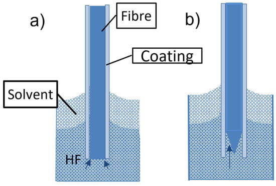
Fiber nanotip sensors can employ commercially available SNOM nanotips, or they can be prepared by thermal pulling or chemical etching. While the thermal pulling requires a sophisticated device, the etching can be realized in a chemical laboratory provided that safety rules for working with hydrofluoric acid are kept. However, nanotips prepared by chemical etching need to be metalized to preserve their mechanical stability. On the other hand, SNOM nanotips are metalized. Nanotips with apex diameters bellow 100 nm can be employed for intracellular measurements. However, in this field, they will compete with PEBBLES (probes embedded in biologically localized environments). Thus fiber-optic nanotip and microtip sensors can be useful for chemical detection in pores, cell tissues, and small drops. Chemical sensing in plant tissues and drops of exudates from plants is possible with fiber microtip sensors[80] and can provide us with information on chemical mechanisms in plant tissues, leaves, etc. Information about concentrations of chemicals in material pores can be employed for investigations of solid catalysts, metal corrosion, etc. One can also expect that fiber-optic microtips and nanotips will be employed for the development of optical tweezers and coupling devices. Fiber nanotips coated with metallic nanoparticles or nanoislands exhibit a very good performance for SERS-based chemical analysis which still is not fully employed.
References
- Wolfbeis, O.S. Fiber-Optic Chemical Sensors and Biosensors. Anal. Chem. 2002, 74, 2662–2678.
- Wolfbeis, O.S. Fiber-Optic Chemical Sensors and Biosensors. Anal. Chem. 2004, 76, 3269–3284.
- Wolfbeis, O.S. Fiber-Optic Chemical Sensors and Biosensors. Anal. Chem. 2006, 78, 3859–3874.
- Wolfbeis, O.S. Fiber-Optic Chemical Sensors and Biosensors. Anal. Chem. 2008, 80, 4269–4283.
- Wang, X.-D.; Wolfbeis, O.S. Fiber-Optic Chemical Sensors and Biosensors (2008−2012). Anal. Chem. 2013, 85, 487–508.
- Wang, X.-D.; Wolfbeis, O.S. Fiber-Optic Chemical Sensors and Biosensors (2013−2015). Anal. Chem. 2016, 88, 203–227.
- Wang, X.-D.; Wolfbeis, O.S. Fiber-Optic Chemical Sensors and Biosensors (2015−2019). Anal. Chem. 2020, 92, 397–430.
- Borisov, S.M.; Wolfbeis, O.S. Optical Biosensors. Anal. Chem. 2008, 108, 423–461.
- Abdelmalek, F.; Lacroix, M.; Chovelon, J.M.; Jaffrezic-Renault, N.; Berkova, D.; Matejec, V.; Kasik, I.; Chomat, M.; Gagnaire, H. Consequences of TiO2 doping on the optical properties of porous silica layers coated on silica optical fibers. Thin Sol. Film. 1999, 340, 280–287.
- Skokankova, J.; Mrazek, J.; Matejec, V.; Hayer, M.; Kasik, I.; Chomat, M.; Berkova, D.; Barau, A.; Zaharescu, M.; Raileanu, M. Properties of xerogel layers for the detection of toluene in water. Mater. Sci. Eng. C 2006, 26, 208–213.
- Abdelghani, A. Jaffrezic-Renault, N. SPR fibre sensor sensitised by fluorosiloxane polymers. Sens. Actuators B-Chem. 2001, 74, 117–123.
- Snyder, A.W.; Love, J.D. Optical Waveguide Theory. Part II Electromagnetic Analysis of Optical Waveguides; Springer: New York, NY, USA, 1983; pp. 203–353.
- Monro, T.M.; Belardi, W.; Furusawa, K.; Baggett, J.C.; Broderick, N.G.R.; Richardson, D.J. Sensing with microstructured optical fibres. Meas. Sci. Technol. 2001, 12, 854–858.
- Matejec, V.; Mrázek, J.; Hayer, M.; Podrazký, O.; Kaňka, J.; Kašík, I. Sensitivity of microstructure fibers to gaseous oxygen. Meas. Sci. Eng. 2008, 28, 876–881.
- Elsherif, M.; Salih, A.E.; Gutiérrez Munoz, M.; Alam, F.; AlQattan, B.; Antonysamy, D.S.; Fawzi Zaki, M.; KYetisen, A.; Park, S.; Wilkinson, T.D.; et al. Optical Fiber Sensors: Working Principle, Applications, and Limitations. Adv. Photonics Res. 2022, 3, 2100371.
- Gupta, B.D.; Kant, R. Recent advances in surface plasmon resonance based fiber optic chemical and biosensors utilizing bulk and nanostructures. Opt. Laser Technol. 2018, 101, 144–161.
- Li, M.; Singh, R.; Wang, Y.; Marques, C.; Zhang, B.; Kumar, S. Advances in Novel Nanomaterial-Based Optical Fiber Biosensors—A Review. Biosensors 2022, 12, 843.
- Boussard-Plédel, C. Chalcogenide waveguides for infrared sensing. In Chalcogenide Glasses: Preparation, Properties and Applications; Adam, J.-L., Zhang, X., Eds.; Woodhead Publishing Series in Electronic and Optical Materials; Woodhead Publishing Limited: Oxford, UK; Cambridge, UK; London, UK; Philadelphia, PA, USA; New Delhi, India, 2014; Volume 44, pp. 381–410.
- Bureau, B.; Boussard, C.; Cui, S.; Chahal, R.; Laure Anne, M.; Nazabal, V.; Sire, O.; Loréal, O.; Lucas, P.; Monbet, V.; et al. Chalcogenide optical fibers for midinfrared sensing. Opt. Eng. 2014, 53, 027101.
- Matějec, V.; Chomát, M.; Hayer, M.; Kašik, I.; Berková, D. Development of special optical fibers for evanescent-wave chemical sensing. Czech. J. Phys. 1999, 49, 883–888.
- Wu, W.; Huang, J.; Ding, L.; Lin, H.; Yu, S.; Yuan, F.; Liang, B. A real-time and highly sensitive fiber optic biosensor based on the carbon quantum dots for nitric oxide detection. J. Photochem. Photobiol. A 2021, 405, 112963.
- Ding, L.; Fan, C.; Zhong, Y.; Li, T.; Huang, J. A sensitive optic fiber sensor based on CdSe QDs fluorophore for nitric oxide detection. Sens. Actuators B-Chem. 2013, 185, 70–76.
- Ding, L.Y.; Ruan, Y.L.; Li, T.; Huang, J.; Warren-Smith, S.C.; Ebendorff-Heidepriem, H.; Monro, T.M. Nitric oxide optical fiber sensor based on exposed core fibers and CdTe/CdS quantum dots. Sens. Actuators B-Chem. 2018, 273, 9–17.
- Pathak, A.; Gupta, B.D. Fiber-Optic Plasmonic Sensor Utilizing CTAB-Functionalized ZnO Nanoparticle-Decorated Carbon Nanotubes on Silver Films for the Detection of Catechol in Wastewater. ACS Appl. Nano Mater. 2020, 3, 2582–2593.
- Fallah, H.; Asadishad, T.; Parsanasab, G.-M.; Harun, S.W.; Mohammed, W.S.; Yasin, M. Optical Fiber Biosensor toward E-coli Bacterial Detection on the Pollutant Water. Eng. J. 2021, 25, 1–8.
- Sun, Y.; Guo, X.; Moreno, Y.; Sun, Q.; Yan, Z.; Zhang, L. Sensitivity adjustable biosensor based on graphene oxide coated excessively tilted fiber grating. Sens. Actuators B-Chem. 2022, 351, 130832.
- Wang, R.; Ren, Z.; Kong, D.; Hu, B.; He, Z. Highly sensitive label-free biosensor based on graphene-oxide functionalized micro-tapered long period fiber grating. Opt. Mater. 2020, 109, 110253.
- Cao, Z.; Yao, B.; Qin, C.; Yang, R.; Guo, Y.; Zhang, Y.; Wu, Y.; Bi, L.; Chen, Y.; Xie, Z.; et al. Biochemical sensing in graphene enhanced microfiber resonators with individual molecule sensitivity and selectivity. Light Sci. Appl. 2019, 8, 107.
- Yu, H.; Chong, Y.; Zhang, P.; Ma, J.; Li, D. A D-shaped fiber SPR sensor with a composite nanostructure of MoS2-graphene for glucose detection. Talanta 2020, 219, 121324.
- Li, W.; Miao, Y.; Guo, T.; Zhang, K.; Yao, J. Nb2CTx MXene-tilted fiber Bragg grating optofluidic system based on photothermal spectroscopy for pesticide detection. Biomed. Opt. Express 2021, 12, 7051–7063.
- Yi, D.; Wang, C.; Gao, L.; Chen, Y.; Liu, F.; Geng, Y.; Zhang, H.; Li, X. Ti3CN MXene-based ultra-sensitive optical fiber salinity sensor. Opt. Lett. 2022, 47, 138–141.
- Baig, N.; Kammakakam, I.; Falathabe, W. Nanomaterials: A review of synthesis methods, properties, recent progress, and challenges. Mater. Adv. 2021, 2, 1821–1871.
- Berneschi, S.; Barucci, A.; Baldini, F.; Cosi, F.; Quercioli, F.; Pelli, S.; Righini, G.C.; Tiribilli, B.; Tombelli, S.; Trono, C.; et al. Optical Fibre Micro/Nano Tips as Fluorescence-Based Sensors and Interrogation Probes. Optics 2020, 1, 213–242.
- Betzig, E.; Trautman, J.K.; Harris, T.D.; Weiner, J.S.; Kostelak, R.L. Breaking the Diffraction Barrier: Optical Microscopy on a Nanometric Scale. Science 1991, 251, 1468–1470.
- Tan, W.; Shi, Z.-Y.; Smith, S.; Birnbaum, D.; Raoul Kopelman, R. Submicrometer Intracellular Chemical Optical Fiber Sensor. Science 1992, 258, 778–781.
- Lewis, A.; Lieberman, K. The optical Near Field and Analytical Chemistry. Anal. Chem. 1991, 63, 625A–638A.
- Lee, S.; Jiao, M.; Zhang, Z.; Yu, Y. Nanoparticles for Interrogation of Cell Signaling. Annu. Rev. Anal. Chem. 2023, 16, 333–351.
- Clark, H.A.; Hoyer, M.; Philbert, M.A.; Kopelman, R. Optical Nanosensors for Chemical Analysis inside Single Living Cells. 1. Fabrication, Characterization, and Methods for Intracellular Delivery of PEBBLE Sensors. Anal. Chem. 1999, 71, 4831–4836.
- Clark, H.A.; Kopelman, R.; Tjalkens, R.; Philbert, M.A. Optical Nanosensors for Chemical Analysis inside Single Living Cells. 2. Sensors for pH and Calcium and the Intracellular Application of PEBBLE. Anal. Chem. 1999, 71, 4837–4843.
- Kopelman, R.; Smith, S.; Tan, W.; Zenobi, R.; Lieberman, K.; Lewis, A. Spectral analysis of surfaces at subwavelength resolution, Proc. SPIE Environ. Process Monit. Technol. 1992, 1637, 33–40.
- Paiva, J.S.; Jorge, P.A.S.; Rosa, C.C.; Cunha, J.P.S. Optical fiber tips for biological applications: From light confinement, biosensing to bioparticles manipulation—Review. Biochim. Biophys. Acta (BBA)-General. Subj. 2018, 1862, 1209–1246.
- Valaskovic, G.A.; Holton, M.; Morrison, G.H. Parameter control, characterization, and optimization in the fabrication of optical fiber near-field probes. Appl. Opt. 1995, 34, 1215–1228.
- Turner, D.R. Etch Procedure for Optical Fibers. US Patent 4,469,554, 4 September 1984.
- Hoffmann, P.; Dutoit, B.; Salathe, R.-P. Comparison of mechanically drawn and protection layer chemically etched optical fiber tips. Ultramicroscopy 1995, 61, 165–170.
- Anderson, G.P.; Golden, J.P.; Ligler, F.S. A fiber tapered optic biosensor: Combination fibers designed for improved signal acquisition. Biosens. Bioelectr. 1993, 8, 249–256.
- Muramatsu, H.; Homma, K.; Chiba, N.; Yamamoto, N.; Egawa, A. Dynamic etching method for fabricating a variety of tip shapes in the optical fibre probe of a scanning near-field optical microscope. J. Microscop. 1999, 194, 383–387.
- Lazarev, A.; Fang, N.; Luo, Q.; Zhang, X. Formation of fine near-field scanning optical microscopy tips. Part I. Rev. Sci. Instrum. 2003, 74, 3679–3683.
- Giannetti, A.; Barucci, A.; Cosi, F.; Pelli, S.; Tombelli, S.; Trono, C.; Baldini, F. Optical fiber nanotips coated with molecular beacons for DNA detection. Sensors 2015, 15, 9666–9680.
- Griffini, D.; Insinna, M.; Salvadori, S.; Barucci, A.; Cosi, F.; Pelli, S.; Righini, G.C. On the CFD analysis of a stratified taylor-couette system dedicated to the fabrication of nanosensors. Fluids 2017, 2, 8.
- Lambelet, P.; Sayah, A.; Pfeffer, M.; Philipona, C.; Marquis-Weible, F. Chemically etched fiber tips for near-fieldoptical microscopy: A process for smoother tips. Appl. Opt. 1998, 37, 7289–7292.
- Stὅckle, R.; Fokas, C.; Deckert, V.; Zenobia, R.; Sick, B.; Hecht, B.; Wild, U.P. High-quality near-field optical probes by tube etching. Appl. Phys. 1999, 75, 160–162.
- Pangaribuana, T.; Jiang, S.; Ohtsu, M. Highly Controllable Fabrication of Fiber Probe for Photon Scanning Tunneling. Scanning 1994, 16, 362–367.
- Koronczi, I.; Reichert, J.; Ache, H.J.; Krause, C.; Werner, T.; Wolfbeis, O.S. Submicron sensors for ion detection based on measurement of luminescence decay time. Sens. Actuators B-Chem. 2001, 74, 47–53.
- Koronczi, I.; Reichert, J.; Heinzmann, G.; Ache, H.J. Development of a submicron optochemical potassium sensor with enhanced stability due to internal reference. Sens. Actuators B-Chem. 1998, 51, 188–195.
- Tai, Y.-H.; Wei, P.-K. Sensitive liquid refractive index sensors using tapered optical fiber tips. Opt. Lett. 2010, 35, 944–946.
- Tan, W.; Shi, Z.Y.; Kopelman, R. Development of submicron chemical fiber optic sensors. Anal. Chem. 1992, 64, 2985–2990.
- Munkholm, C.; Walt, D.R.; Milanovich, F.P.; Klainer, S.M. Polymer Modification of Fiber Optic Chemical Sensors as a Method of Enhancing Fluorescence Signal for pH Measurement. Anal. Chem. 1986, 58, 1427–1430.
- Vo-Dinh, T.; Kasili, P.; Wabuyele, M. Nanoprobes and nanobiosensors for monitoring, and imaging individual living cells. Nanomed. Nanotechnol. Biol. Medic. 2006, 2, 22–30.
- Wanga, S.; Ye, F.; Lang, X.; Fei, D.; Ge, Y.; Turner, A.P.F. Detection of changes in sub-plasma membrane microdomains in a single living cell by an optical fiber-based nanobiosensor. Austin J. Nanomed. Nanotechnol. 2014, 2, 1022.
- Barker, S.L.R.; Bjorn, A.; Thorsrud, B.A.; Kopelman, R. Nitrite- and Chloride-Selective Fluorescent Nano-Optodes and in Vitro Application to Rat Conceptuses. Anal. Chem. 1998, 70, 100–104.
- Tan, W.; Shi, Z.-Y.; Kopelman, R. Miniaturized fiber-optic chemical sensors with fluorescent dye-doped polymers. Sens. Actuators B-Chem. 1995, 28, 157–165.
- Rosenzweig, Z.; Kopelman, R. Development of a submicrometer optical fiber oxygen sensor. Anal. Chem. 1995, 67, 2650–2654.
- Tan, W.; Kopelman, R.; Barker, S.L.R.; Miller, M.T. Peer Reviewed: Ultrasmall Optical Sensors for Cellular Measurements. Anal. Chem. 1999, 71, 606A–612A.
- Hossein-Zadeha, M.; Delgado, J.; Schweizer, F.; Lieberman, R. Sub-micron Opto-Chemical Probes for Studying Living Neurons. In Proceedings of the SPIE 10051, Neural Imaging and Sensing, San Francisco, CA, USA, 8 February 2017. 100510G; paper 100510G(9pp).
- Bui, J.D.; Zelles, T.; Lou, H.J.; Gallion, V.L.; Phillips, M.I.; Tan, W. Probing intracellular dynamics in living cells with near-field optics. J. Neurosc. Methods 1999, 89, 9–15.
- Vo-Dinh, T.; Kasili, P. Fiber-optic nanosensors for single-cell monitoring-Review. Anal. Bioanal. Chem. 2005, 382, 918–925.
- Alarie, J.P.; Vo-Dinh, T. Antibody-Based Submicron Biosensor for BenzoPyrene DNA Adduct. Polycycl. Arom. Compd. 1996, 8, 45–52.
- Cullum, B.M.; Griffin, G.D.; Miller, G.H.; Vo-Dinh, T. Intracellular Measurements in Mammary Carcinoma Cells Using Fiber-Optic Nanosensors. Anal. Biochem. 2000, 277, 25–32.
- Kasili, P.M.; Song, J.M.; Vo-Dinh, T. Optical Sensor for the Detection of Caspase-9 Activity in a Single Cell. J. Am. Chem. Soc. 2004, 126, 2799–2806.
- Barker, S.L.R.; Kopelman, R. Development and Cellular Applications of Fiber Optic Nitric Oxide Sensors Based on a Gold-Adsorbed Fluorophore. Anal. Chem. 1998, 70, 4902–4906.
- Cordek, J.; Wang, X.; Tan, W. Direct Immobilization of Glutamate Dehydrogenase on Optical Fiber Probes for Ultrasensitive Glutamate Detection. Anal. Chem. 1999, 71, 1529–1533.
- Song, J.M.; Kasili, P.M.; Griffin, G.D.; Vo-Dinh, T. Detection of Cytochrome c in a Single Cell Using an Optical Nanobiosensor. Anal. Chem. 2004, 76, 2591–2594.
- Petry, R.; Schmitt, M.; Popp, J. Raman spectroscopy—A prospective tool in the Life Sciences. Chem. Phys. Chem. 2003, 4, 14–30.
- Jonathan, P.; Scaffidi, J.P.; Gregas, M.K.; Seewaldt, V.; Vo-Dinh, T. SERS-based plasmonic nanobiosensing in single living cells. Anal. Bioanal. Chem. 2009, 393, 1135–1141.
- Chen, Z.; Dai, Z.; Chen, N.; Liu, S.; Pang, F.; Lu, B.; Wang, T. Gold Nanoparticles-Modified Tapered Fiber Nanoprobe for Remote SERS Detection. IEEE Phot. Technol. Lett. 2014, 26, 777–780.
- Lucotti, A.; Zerbi, G. Fiber-optic SERS sensor with optimized geometry. Sens. Actuators B-Chem. 2007, 121, 356–364.
- Wang, J.; Geng, Y.; Shen, Y.; Shib, W.; Xu, W.; Xu, S. SERS-active fiber tip for intracellular and extracellular pH sensing in living single cells. Sens. Actuators B-Chem. 2019, 290, 527–534.
- Hutter, T.; Elliot, S.R.; Mahajan, S. Optical fibre-tip probes for SERS: Numerical study for design considerations. Opt. Express 2018, 26, 15539–15550.
- Zheng, X.T.; Hua, W.; Wang, H.; Yang, H.; Zhoud, W.; Li, C.M. Bifunctional electro-optical nanoprobe to real-time detect local biochemical processes in single cells. Biosens. Bioelectron. 2011, 26, 4484–4490.
- Kasik, I., Mrazek, J., Martan, T., Pospisilova. M.., Podrazky, O., Matejec, V., Hoyerova, K., Kaminek, M. Fiber-optic pH detection in small volumes of biosamples. Anal. Bioanal. Chem. 2010, 398, 1883–1889.