The recent increase in the use of carbonless energy systems have resulted in the need for reliable energy storage due to the intermittent nature of renewables. Among the existing energy storage technologies, compressed-air energy storage (CAES) has significant potential to meet techno-economic requirements in different storage domains due to its long lifespan, reasonable cost, and near-zero self-decay.
1. Introduction
The increased penetration of renewables into the energy mix of many countries in recent times has led to the inclusion of renewables as part of baseload generation. This has led to failure in some of the world’s most energy-abundant regions, like Texas
[1] and South Australia
[2]. Despite existing infrastructure and robust management systems, political and economic problems coupled with extreme weather events have resulted in higher numbers of grid failures
[3]. The uncertainty associated with intermittent renewables requires reliable utility-scale long-term energy storage to provide grid stability and energy security. Except for hydropower storage, in earlier times, many other types of energy storage systems did not meet utility scale requirements. Aside from basic energy-warehousing needs, storage is also used to provide other ancillary grid services to ensure grid stability and meet regulatory requirements.
Pumped hydroelectricity storage (PHS) is regarded as the industry standard for grid-scale energy storage applications. It has good round-trip efficiency (RTE), with values as high as 85%
[4]. As a generation-integrated storage technology, it can be a part of a hydropower generation plant, enabling it to meet utility-scale requirements at minimal additional cost. It can provide a wide range of support on a large scale. It can source and sink hundreds of megawatts to stabilize the grid and meet demand/supply surges. The system uses simple, mature technologies such as turbines, pumps, motor generators, and governors, giving it excellent throttling control. PHS faces geographical and geological constraints that are compounded by global water issues and other negative environmental impacts due to large dams. The technology suffers from a low energy density and high capital costs, which create a barrier to obtaining capital. These issues hinder its suitability for small-scale or standalone applications
[5].
Advancements in material technology have led to high power densities and good round-trip efficiencies in chemical batteries. Combining these batteries with switch mode converters, which are now a mature technology, can yield round-trip efficiencies (RTE) as high as 90%. Lithium-ion batteries are considered state-of-the-art batteries; they have a lifespan of 7 years or more, according to
[6]. Chemical batteries often have fewer active cycles than those quoted, and this is influenced by the depth of discharge, storage temperature, and other factors based on cell chemistry. Batteries have a limitation in that their capacity declines over their operational lives. The maximum depth of discharge depends on the electrode materials and the electrolyte used
[7].
Supercapacitors (SCs) are rapid charge and discharge devices that are like conventional capacitors but with greater charge-holding capabilities. They are electrochemical capacitors with multiple electrical conductor layers separated by a porous insulator material. Supercapacitors have the advantage of a simple setup, using power electronics to link the load and power source. Due to low-voltage operation, SCs need to be strung together, resulting in an unequal voltage distribution that cannot be corrected by equalization charge mode that is applicable to chemical batteries. This causes supercapacitors to demonstrate limited performances
[8]. They can hardly retain their charged content. Once charged, the stored energy quickly self-depletes. The decay rate for an improved SC made with a solid-state material is 30% within 36 h, according to
[9]; this is an improvement from 40.1% in insulator types. Supercapacitors are good for rapid sinks or sources of energy. They have good prospects for use as short-term storage devices in regenerative braking systems
[10]. A low rate of self-decay and high energy density are critical requirements for grid applications that are lacking in supercapacitors.
Flywheel energy storage (FES) systems, like supercapacitors, are capable of providing rapid energy sinks or sources for emergency, on-demand applications. They have unlimited temperature-independent deep-discharge capabilities. Improvements in magnetic bearing and vacuuming to reduce friction and air resistance, respectively, have helped increase the FES’s speed to 40,000 rpm, which increases its energy density compared to earlier versions. Although the improvement of a flywheel is limited to increasing its disc speed in line with the torque and angular speed power relation P = T𝜔, the bearing limits the lifespan of flywheel storage
[11]. Due to its high rate of self-decay, a flywheel backup facility requires a high level of maintenance energy to ensure that it retains its full state of charge. Flywheels do not meet the requirements of a main storage facility due to their flaws. However, they are used in assisting roles as ancillary grid services to provide short backups for peaker plants to reach their full load after start-up in case of power failure.
The flexibility of the normal operation processes of CAES gives it advantages over other types of energy storage. Unlike other types of storage, its energy input does not have to be electrical power. The input may come from a mechanical source like a rotating shaft or reciprocatory system, a pressurized fluid power source, or a low-pressure pneumatic source. These unique attributes drive interest in compressed-air energy storage (CAES).
2. Compressed Air Energy Storage System
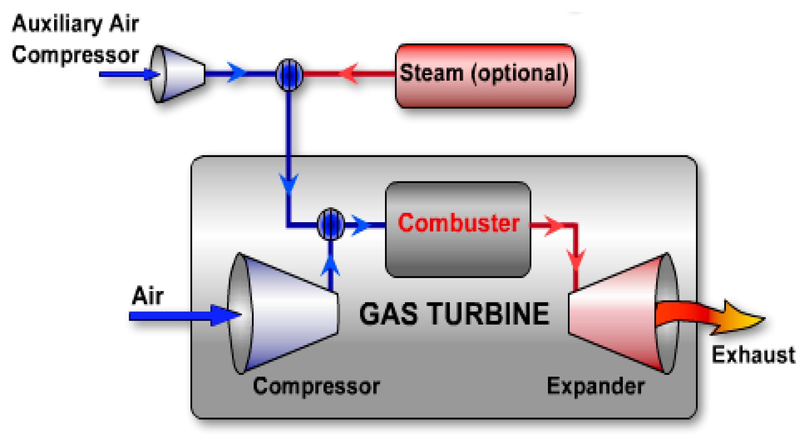
In medieval times, compressed air first found an energy application in air injection (AI). The use of compressed air energy storage at utility-scale was not popular because compressed air was used directly at that time due to a lack of pressure storage technologies. For small-scale applications, hand, foot, and even animal-powered bellows were used to pressurize air to increase the temperature of burning shells or wood, which acted as fuel. Increasing the burning efficiency seems to have been the main aim, although the higher temperatures attained due to AI made it possible to use compressed air in foundries. With the emergence of compressed-air storage capabilities, CAES works in a supporting role, providing power augmentation in fuel-powered generators to increase the efficient combustion of fuel.
As demonstrated in Figure 1, the auxiliary injection of compressed air into the combustors not only increases the power output but also helps the main compressor pull more compressed air into the gas turbine.
Figure 1. Basic air injection power augmentation in a gas turbine power plant.
2.1. A Basic CAES System
The operation of a CAES system is similar to a jet engine in terms of its components, which are mainly a compressor and an expander. The major difference is that a CAES system stores energy as static pressure in a compressed air chamber, and in some cases, heat is captured in a thermal store. It also uses a motor/generator during charging and discharging modes to store and regenerate electrical power, respectively. Like other energy storage systems, the actual energy reservoir in a CAES system comprises the compressed air unit, converter devices, and other ancillary units. Since air is a gas, compression or expansion occurs with a concomitant increase and decrease in temperature, respectively. When compressed air and thermal capture are carried out, CAES is best described as “thermomechanical storage”. It is considered mechanical storage if only air is stored as static pressure. Despite this limitation in the description, all compression and expansion processes are deemed thermomechanical processes due to changes in the thermal state.
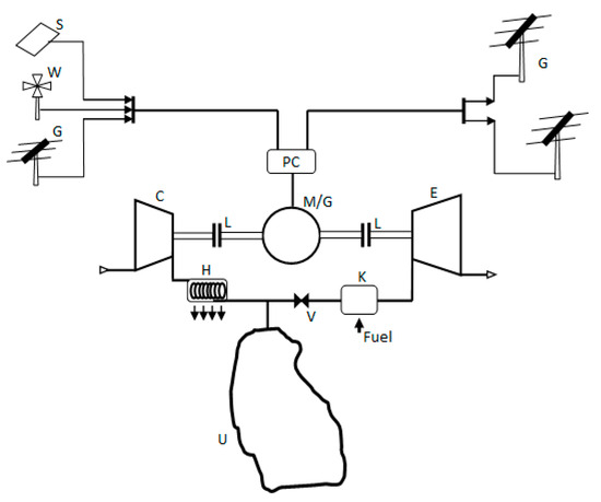
A basic example of a CAES system is shown in Figure 2 below. The electrical energy to charge the system can come from a variety of sources based on availability, such as wind (W), solar (S), or even a utility supply grid (G).
Figure 2. Basic diabatic-type compressed-air energy storage.
2.1.1. Classification of CAES Systems
There are three different concepts that capture the emergence of CAES, from its early usage to recent developments in the modern era. This also heralds a transition in the role of compressed air, which was first used as a supporting energy system in power plants, to the main storage system itself. Although Michael Nakhamkin, considered the father of modern CAES, as per Ref.
[12], categorized CAES systems into generations of simple and complex CAES systems, such classifications do not capture the role of fuel or compressed air or how the thermal gradient caused by the compression or expansion conversion processes is used, like in
[13].
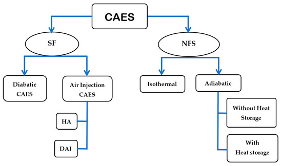
Figure 3 captures the various types of CAES systems and their sub-classes. To ensure that old and new developments and different variations in CAES technology are captured, CAES systems have been classified into two types.
Figure 3. Types of compressed-air energy storage (CAES) technologies with variants.
Supplementary Fuel CAES:
As carbonized CAES, supplementary fuel CAES systems are normally fossil-fuel-powered plants or normal compressed-air power systems that use compressed air to enhance power performance or reduce emission footprints. The compressed air in an SFCAES system can serve as the main power system or as a supplementary system. Stoichiometric ratios of air/fuel can be improved via a better air mass intake, which reduces fuel consumption and makes these power systems more efficient.
Air Injection CAES:
These types of CAES operate such that fuel is used either as the main energy system or compressed air plays supplementary role. Types of air-injection power-augmentation CAES systems can include humid air injection (HAI), in which an air-humidifying unit is used before injecting compressed air to the expander, and dry air injection (DAI), in which compressed air is fed into the system as it is. In both instances, compressed air is injected into a fuel fed or ignited power generation system which is the main power system.
Diabatic CAES:
A diabatic CAES system is also a carbonized type of energy storage system. Unlike air injection CAES, compressed air is the main power system. Fuel is used in an assistive role to increase the turbine’s output power by increasing the inlet temperature to prevent damage due to low temperatures.
These systems are suitable for large-scale grid systems or to provide backup to an entire city for an extended period of time. However, they suffer from low efficiency due to the dissipation of compression heat through intercoolers into the surrounding environment. These systems also suffer huge losses due to incomplete expansion.
Non-Supplementary Fuel CAES:
These are carbonless CAES systems in which the heat of compression is either dissipated away during compression or harvested for reinjection during expansion. They do not require fuel or use external heat sources for their operation. Based on the type of compressor used and the nature of its operation, NSF-CAES systems can take two forms.
Adiabatic CAES (A-CAES):
This is a carbonless type of CAES whose compression heat is allowed to increase without dissipation. The compression heat and compressed air can be stored together in the same storage unit. An A-CAES system does not use intercoolers or any other means of thermal extraction or capture. The high temperature generated results in low masses of air in the storage units and a concomitant poor energy density. Aside from this, storage units with the necessary thermal and structural properties will be difficult to develop and costly to build.
Advanced Adiabatic CAES (AA-CAES):
Instead of allowing compression temperatures to rise unabated, intercoolers or other means of heat extraction and storage can be used. Other attempts at combined heat and power systems were explored in
[14] with the aim of using the compression heat for other purposes. But in an AA-CAES system, the compression heat is stored in a thermally insulated unit, and the compressed air is stored in a separate storage chamber. Compression heat can be captured through heat-absolving and heat-releasing structures, as in
[15][16][17].
Isothermal CAES:
This type of CAES system does not need high-temperature machines or thermal storage. This can be achieved via a variety of strategies for abating an increase in temperature in the compression unit. The compression work losses due to thermal leaks associated with adiabatic CAES systems are prevented in isothermal CAES systems. The concept of the polytropic tuning of energy-converting machines to shift their thermodynamic processes to meet near-isothermal conditions has significant prospects. Although it is impossible to attain an ideal isothermal process because a thermal gradient needs to exist before heat transfer can occur, many quasi-isothermal CAES processes have improved compression efficiency compared to baseline compression techniques.
2.2. Flaws of Early CAES
The major problem with early-generation CAES systems (both AI and diabatic types) is their carbon-heavy nature. The recent popularity of carbonless energy systems means that the storage of fossil fuel energy receives little support and funding. Fuel-based CAES systems are no longer acceptable to many policymakers. Also, the operating processes early CAES systems made them prone to significant losses due to inefficient compression and expansion processes. Despite the use of fuel, their round-trip efficiency values are low compared to other battery technologies. The losses associated with compression are due to increases in temperature, while those associated with expanders are due to the loss of exergy associated with valves and rapid expansion, which causes cooling. Charging such systems from the grid with a normal tariff regime will only worsen techno-economic parameters. Due to these disadvantages caused by poor RTE and low DOD values and the need for fuel, early CAES systems are best charged from arbitrage-prone renewables to reduce curtailments.
2.3. The Evolution of Energy-Converter Machines in CAES Systems
To eliminate diabatic-type CAES, the shift towards carbonless energy storage ushered in adiabatic and isothermal types of CAES. Both these types of CAES use processes that focus on efficient energy conversion, improved topology to ensure the optimal performance convergence of all subunits, design scalability, and efficient throttling control. Since the conventional thermodynamic process of compression and expansion is isentropic in nature, approaches that guide its operation toward an ideal process are deemed most acceptable to reduce losses.
The combination of CAES and thermal storage attracts the interest of researchers because as a thermomechanical storage system, CAES involves thermal and pneumatic processes in its operation. The energy density of the thermal storage is higher than that of CAES, although both increase with temperature and pressure, respectively. In
[18], for a temperature difference of 100 °C, an energy density of 1.1 MJ/L was attained compared to 0.11 MJ/L at 200 Bar for CAES if isothermal expansion is assumed. The high energy density of the thermal storage can improve the footprint of CAES if heat storage is integrated into it. Such a high energy density requires temperatures at supercritical values; the disadvantage of this is that a high thermal gradient increases the loss of energy through thermal leaks. The RTE of a hybrid thermal and AA-CAES system is higher than that of a conventional CAES system, but it does not solve the problem of the high rate of self-decay of these types of storage. Complexity issues in thermomechanical systems reduce their suitability for small-scale and behind-the-meter applications. They can be used for daily cycling, but the prospects of use in long-term storage or energy cloud services are poor. Low-pressure ratios induce lower compression losses compared to those with high-pressure ratios. This can be used to improve the efficiency of energy-converting machines, even in expansion mode.
A lower temperature range of 90–200 °C with air pressure stored at 150 bar was proposed in
[16]; this system attained an efficiency of 54–67%. It used a combination of series-connected radial compressors which could rotate at different speeds to meet the desired parameters at each stage. Each stage also had its own combined intercooler and heat absorber for thermal storage. The operation was such that the generated heat was harvested for storage while the intercooler dissipated the remaining low-grade heat away, reducing the compression work for the subsequent stage. This configuration had the advantages of the rotating machines’ quick startup and fast cycling compared to high-temperature ACAES systems. Uncontrolled temperature increases were prevented via intercoolers to help improve the converters’ polytropic indices. This was achieved by dissipating the compression so that the subsequent compressor unit received cooler compressed air. Despite these attributes, the system faced similar problems of variations in storage pressure and a high level of resident energy, which resulted in a poor DoD. The energy-converting machine still wasted energy through heat dissipation, but it had better efficiency and operated within a low temperature range.
2.4. Isothermal CAES Based on Hydropneumatic Converters
The further improvement of CAES to ensure near-isothermal operation becomes necessary. This is to prevent the thermally induced losses that are common with adiabatic and diabatic types of CAES. To create an ECM capable of near-isothermal operation, the approaches used in medieval times give an idea of the principle of hydropneumatics, which was first developed as tromps
[19][20] in the 1700s. Tromps are near-isothermal river-flow-charged hydraulic compressors that operate based on the reciprocatory movement of a fluid in a column. The application of this principle without the use of a river’s flow was first achieved by Humphrey to pump water at a low pressure and high volume in
[21].
An LP compressor operates by opening the inlet valve to pull in air to be compressed. The fluid level in the LP chamber is reduced by pumping out its fluid content until the bottom dead center is reached. After the intake stroke, the inlet valve is closed, after which the hydraulic pump injects fluid into the LP chamber to raise the fluid level. Increasing the fluid level pressurizes the trapped air until the desired pressure or top dead center is reached. The outlet valve can be opened to allow compressed air into the storage vessel. Similar to solid piston compressors, continuous compression strokes will occur until the desired storage pressure is attained. In the expander mode, high-pressure air is allowed into the fluid-filled chamber through the inlet valve while the outlet valve is closed. According to Pascal’s law, the distribution of pressure ensures that the fluid and air pressures are the same except when the contact surface areas are not of the same ratio. The base hydraulic valve is opened to allow pressurized fluid to flow out of the chamber to drive the hydraulic motor downstream. The mechanical work generated by the motor can be used to drive the generator. The trapped compressed air expands as its pressure value reduces toward the ambient while pushing down the hydropneumatic interface until the bottom dead center is reached.
Using self-sealing moving fluid, LPs do not have the problems of friction or seal abrasion that plague conventional solid-piston energy converters. This enables them to operate at lower noise levels and eliminate seal maintenance. Near-reversible attributes ensure minimal losses regardless of the mode of operation, either as a compressor or an expander. Therefore, it is possible to use a single device in different modes to eliminate the cost and complexity problems of having separate units in the same CAES system. Liquids have good form factors, enabling them to conform to the geometry of the different containers in which they are placed.
2.4.1. Accumulator-Based Isothermal CAES
Accumulator-based CAES gained popularity due to its simplicity and similarity in principle to pumped hydroelectricity storage (PHS), except it is a smaller device. Generally, accumulators are applied in short-term energy storage in hydraulic systems to reduce the size of the pump and the prime mover. Accumulators are used in regenerative breaking
[22][23] and to absorb pressure surges and reduce shocks. Unlike the dedicated storage unit in many CAES systems, the advantage of an accumulator is its combined role as an energy storage and converter device. Aside from their simplicity, accumulators enable direct integration into the generated asset
[24][25].
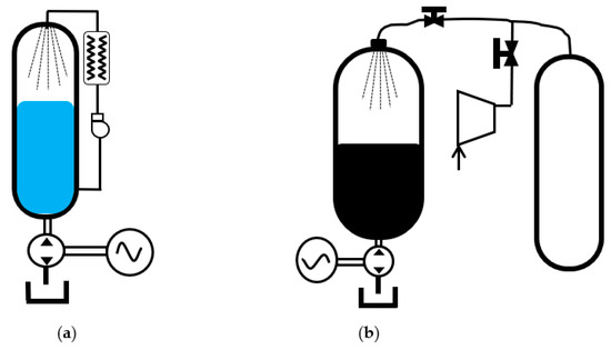
The team at Oak Ridge Laboratory used a regenerative pump using static pressure already in the vessel to generate a mist that cools the chamber, as shown in Figure 4a. A mist-generating pump can have its feed line integrated with a heat exchanger for heat injection or removal.
Figure 4. Accumulator CAES with (a) a regenerative heat exchanger; (b) isobaric CAES using double vessel.
Despite this, variations in logarithmic pressure worsen efficiency and deflate its simplicity and cost advantage. Also, as a closed-cycle system, accumulator-based CAES has poor energy density. To improve efficiency, via a simulation analysis, the authors of
[26] estimated of an RTE of 66% which was obtained using isothermal charging that combined mist spray and a slow charging rate to reduce the increase in temperature.
Figure 4a demonstrates that the mist-spray method is such that the spray fluid can be cooled during compression and heated during expansion, which improves heat transfer. Despite the fact that the initial and final charge pressures have a pressure ratio of 2, which increases the RTE by 5%, the energy density is poor, and variations in output power with the vessel’s energy content remain a problem. Such a system cannot work with a constant load profile over its entire discharge period. If an accumulator with a higher peak pressure capacity is used, the contribution to the increase in energy density seems to be less significant due to the wide pressure variation.
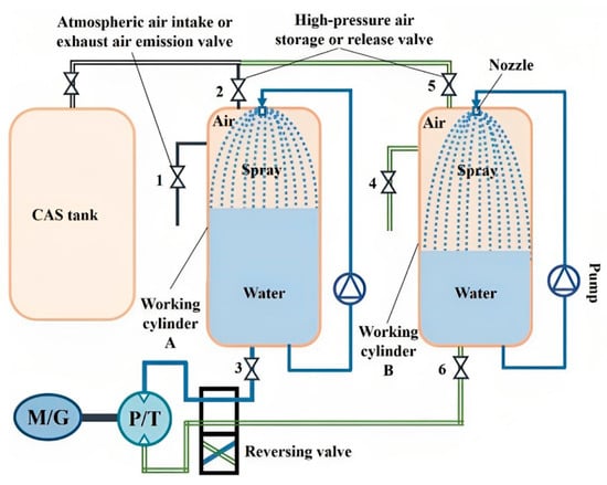
In an approach to improving the RTE by reducing the rapidly changing accumulator pressure, the authors of
[27] analyzed a proposed near-constant-pressure storage system using two storage vessels. Auxiliary storage compensates for a decline in pressure in the main accumulator chamber, as shown in
Figure 4b.
During this period, fluid from the discharging accumulator experiences a rapid decline in pressure that is similar to the two situations in Figure 4. The dead volume limitation problem that is common in normal accumulator based CAES is solved by having two open accumulators connected to operate in switch mode instead of one. The use of an open accumulator as a converter instead of the normally closed configuration allows for the expended compressed air from each accumulator to be removed alternatively through exhaust valves 1 and 4. Any of the pressure-depleted accumulators can be recharged again from CAS tank inlet valves 2 and 5. To charge the CAS tank, reverse positions of the hydraulic and pneumatic directional control valves are used, operation is also in switch mode. Alternative switching operations, such as having one accumulator discharge its exhaust while the other one is charged from the CAS tank, help to ensure the system’s continuous operation until the main CAS tank pressure is depleted. This creates a wider operational range than that of a basic accumulator CAES. Although a near-isothermal profile is achieved and the energy density is improved, problems of a limited DOD persist due to the effective operational range of the hydraulic motor. The sizes and cost of accumulators used as energy converters are larger issues.
2.4.2. Liquid Piston Based CAES
The combined role of accumulators as energy converters and storage is plagued by poor efficiency and energy density problems. Rapid declines in pressure also impose a load profile that must follow declines in storage pressure or the system risks overload and shutdown. This necessitates a system subunit that works effectively as a converter or as storage only. A purpose-developed energy-converting machine should have better performance attributes for specific needs. A liquid piston using an air–fluid interface fits into the already established advantages of hydropneumatics, as previously explained.
Described as a switch-mode liquid piston (SMLP), its operation is similar to that of the paired accumulators in Figure 5. To improve the quasi-isothermal conditions, the LP chamber has copper tubes arranged in a honeycomb manner which act as heat exchangers and thermal storage integrated into the liquid piston chamber. The alternately switched LPs can operate in either compressor mode or expander mode, depending on the position of the directional valve.
Figure 5. Open accumulator as an energy converter in near-isothermal CAES
[28].
3. Optimization Strategies for Hydropneumatic Energy Converters
The LP compression process follows a compressed-push sequence. After a full compression stroke, the LP charges the storage chamber unit freely until the pressure gradient between the storage chamber and the LP chamber is near zero. This is in line with Fick’s law of diffusion. Additional compression energy is needed to push the remaining compressed air content of the LP chamber into the storage unit after the initial isochoric charging. The last isobaric charging process requires the hydropneumatic interface to move upward until a dead volume is reached. Both processes can be explained via an extensive analysis of pneumatic power, as in
[29], and the pneumatic flow assessment presented in
[30]. The total pneumatic power in the LP chamber is deemed to have two components: real power that can be converted into useful work through the expansion process and transport power which is needed to push the real power downstream, usually from its present location to the desired location. Decreases in diffusion while the vessel is being filled from the LP chamber due to a decline in pressure and a simultaneous increase in the compressibility of the storage unit due to an increasing storage pressure create a mismatch.
In all studies that used an SMLP with only a single-stage ECM, a substantial residual pressure remains unused in each LP chamber after each expansion stroke due to incomplete expansion. It is discharged away through exhaust valves, contributing to conversion losses. Using residual energy that remains in the LP chamber after the expansion stroke is a key effort needed to improve the RTE. It can reduce conversion losses for SMLP-configured CAES and also ensure a better load-handling profile.
Instead of a dedicated pressure intensifier or booster, a novel approach that prevents the waste of exhaust pressure and turns it into useful output work was patented in
[31]. Series-linked LPs with geometry designed for a specific pressure range were used to spread the pressure ratio of each stage over two-stage compressors. In compression mode, each LP has an optimal pressure ratio of 4 to raise the final pressure to 200 bar from the pressure input of 12.5 bar. The expansion process works in a similar way, ensuring that the exhaust pressure is close to the ambient pressure. Due to the wider range of operating pressure capability of LP compressors, the effect of a rapid decline in vessel pressure is lessened but is still present. The limitations of this configuration are the irreversible thermodynamic losses of the machine and the process itself, the limited DoD, and the complexity.
4. Strategies for Optimizing CAES Systems
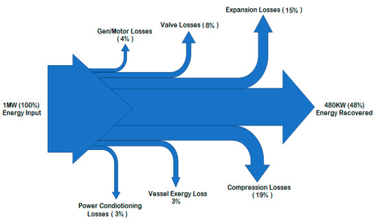
The characterization of losses gives insight into the flow of energy and where optimization can focus to improve performance. Using average values of CAES subunit losses retrieved from the literature, estimates at each stage can be computed and used to analyze cycle loss. Although ideal thermodynamic tubes/pipes that form connecting links among all subunits are assumed, in reality, this is not possible. As indicated in the energy map of a generic CAES system in Figure 6, energy converters, regulating valves, and directional control valves account for substantial losses. These losses are due to the poor polytropic indices of energy-converting machines and changing storage pressure. Far from ideal scenarios, the prospect of polytropic tuning to shift it from an adiabatic-leaning value of 1.4 towards a near-isothermal value of 1 in hydropneumatic CAES is desired. In adiabatic CAES, efficient thermal capture is the main goal to prevent or reduce thermal losses.
Figure 6. Sankey power flow map of CAES, showing the composition of losses due to component devices.
Other aspects of required optimization are parameter convergence problems, which affect the performance of the entire CAES system. Another aspect that requires optimization is parameter convergence, which affects the performance of the entire CAES system. A study of the existing generic configuration of CAES subunits indicates that a significant parameter mismatch exists between hydraulic and pneumatic subunits in hydropneumatic CAES. In AA-CAES, variations in sensible heat thermal storage and compressed air storage pressure parameters, mismatch, and throttling-induced losses are common
[32]. This leads to irretrievable losses due to a lack of process synergy in different stages of compression and expansion. The DoD depends on a wide pressure range of ECMs or the use of other methods that can combine the vessel’s isobaric control with constant air density even with a depleting mass of air. The RTE depends on the optimal pressure range of the ECM, which drives the need for isobaric storage. Other sources of losses are process-induced losses within these combinations of factors, and the interdependent nature of the parameters make the optimization of CAES a multi-objective optimization. Therefore, the optimization of each subunit must meet the specific parameter requirements of the other subunits connected to it.
4.1. Optimization Strategies for a Liquid Piston Compressor/Expander
An LP’s prospect of meeting the requirements needed for efficient operation in different storage domains led to an increase in interest in and a search for various methods that will further enhance its performance. This caused a significant increase in research output, most of which was carried out to address specific or combined needs. Although previous research focused on improvements in near-isothermal operation, other areas like power density, integration with power generation assets, isobaric control, and even hybridization with solid pistons are now common areas of research. Optimization strategies are designed to maximize these desired performance metrics and reduce losses. To minimize compression losses, a near-isothermal process is sought. The ideal isothermal energy used to compress a given volume of air V by a compression ratio r in an ideal isothermal scenario is given by
Although impossible to attain, schaolrs can use this as a measure of compression efficiency to benchmark the performance of compressors. An analogous expansion scenario can be applied to derive the expansion efficiency. The rate of the injection of a fluid into the LP chamber follows a trajectory that creates a compression profile ζc, which is different from the ideal isothermal profile. If schaolrs compare both conditions, schaolrs can derive the compression efficiency as
Similarly, the expansion efficiency can be defined as
where
𝑊𝑖𝑛(ζc) is the work done using the compression profile
ζc, and
𝑊𝑜𝑢𝑡(ζe) is the actual expansion work that follows the trajectory of
ζe. The energy generated from
𝑊𝑜𝑢𝑡(ζe) is lower than ideal expansion work
𝐸𝑉. Ideally, the time needed to attain isothermal compression will be so long as to allow for a thermal gradient of zero. In reality, this is not the case; compression takes less time and generates heat that cannot be dissipated away faster than it is generated. The changes in the rate of the flow in and out of the hydropneumatic chamber create two parameters that require optimization. Different approaches are already in use, while other methods are still being studied.
4.2. Power Density Improvement Strategies
The power density of an LP compressor/expander can be derived from isothermal expansion work, LP displacement, and the compression or expansion time described in Equations (6) and (7). In pneumatics, poor power density problems are generally solved by oversizing the energy converter and storage to ensure that surge loads do not cause a forced shutdown. In LPs, such an approach only worsens the already-poor power density parameter. Aside from the high capital cost of acquiring machines with larger ratings, running costs increase due to the power consumption of an oversized electric motor and hydraulic pump. Various strategies used to increase the power density of hydropneumatic systems are also applicable to improving their efficiency. Although reducing fluid displacement plays a significant role in power density improvement, it is difficult to combine such a method with conversion efficiency improvement. From Equations (6)–(9), the competing natures of conversion efficiency and power density show that the optimization of one parameter imposes a trade-off on the other. Therefore, improving both metrics requires an optimization strategy that combines power density improvement with near-isothermal operation to increase efficiency.
The following strategies have been used to improve the power density of LPs. Some of the listed strategies improve both the power density and conversion efficiency.
5. Storage Units for Compressed-Air Energy Storage Systems
5.1. Types of Storage Units for CAES
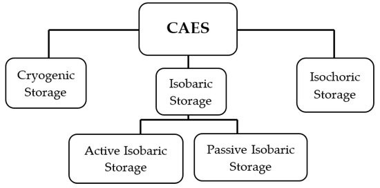
Storage units for CAES are of three different types based on their design and peculiarities of operation, as demonstrated in Figure 7. The classification also indicates efforts to improve the energy density and RTE of storage units and improve the suitability of CAES for different domains of application. Without regard to scale, classification is based on pressure variation and how it is controlled while focusing on the state of the stored compressed air. The following figure captures various types of pressurized storage used for CAES.
Figure 7. Types of high-pressure storage units applicable in CAES.
5.2. Energy Density and Storage Units for CAES
An increase in storage pressure is the key enabler of the energy density of a CAES battery. Small gas-pressure vessels have gone through five generations of development, from all-metal through overwrap, metal-lined Type III vessels to all-composite, lightweight Type V vessels. For non-utility scale applications, the early cylinders were heavy, had low to medium pressure capabilities and low safety properties. If metal types, mostly Type I or II cylinders, explode, they will release shrapnel and can cause severe bodily injuries or death
[33]. Due to safety concerns, these types of cylinders require handling by specially trained personnel. Also, their poor energy densities do not make them attractive for use in small-scale CAES due their low-pressure capabilities, meaning that they must have large footprints and cannot easily fit into existing physical assets like buildings. Improved material technologies, especially the emergence of composite materials as lightweight cylinders for natural gas and hydrogen storage, have opened up opportunities for CAES applications. Newer-generation composite-based pressure vessels of the Types III, IV, and V are considered state-of-the-art cylinders for various applications. They are lightweight, can be designed for high pressure, are not prone to corrosion, and do not produce shrapnel if a crack occurs
[34]. New Type V all-composite cylinders can handle extreme operating pressures of 10,000 psi or more
[35]. That is more than 10 times the storage pressure of the Alabama plant. Using this type of cylinder enables CAES to be a modular BESS that can be configured together for desired specifications. Gas cylinders can be made to have two ports for use as an open accumulator.
6. The Viability of CAES in Different Storage Domains
Down-scaling a utility-scale CAES design for small-scale, behind-the-meter, and standalone systems or integrating it into a power generation system using the same types of subunit devices is not suitable. The way in which the subunits are connected together forms a topology that works best when used in specific domains. A careful analysis of the combination of subunit types and topology is necessary so as not to worsen performance metrics. Since the highest losses in CAES come from energy conversion, an optimized ECM design is needed regardless of the scale or domain of use. The focus of this analysis is on subunit-to-subunit and subunits with topology selection. Application domain requirements differ; therefore, the types of topology or component units should be such that they ensure that the domain needs are met.
6.1. Grid-Scale Batteries
Due to the low energy density of pneumatic systems, ECMs for grid-type storage cannot be of the pneumatic type. In
[36], a power density of 2.9 MW/m
3 was derived through a variety of LP design improvements. It is considered the most optimized LP in the literature thus far. Despite this, its power density is still poor compared to rotary converters, which can have speeds of more than 10,000 rpm. A high angular speed enables it to have a significantly higher power density than low-frequency hydropneumatic converters
[37].
6.2. Behind-the-Meter Application
Due to the use of energy from utility suppliers that carry tariff charges, storage and conversion efficiency are metrics that guide the selection of components for CAES in this domain. Although an efficient system is desired, the availability of electricity is often a higher priority in micropower systems. The high power density of rotating converters, which is due to their high angular speed, is negated by their poor efficiency. Combinations of high-pressure hydropneumatic-type ECMs and storage units that operate at constant pressures are the most suitable. Storage units can be aboveground or fit into physical structures. The storage needs to be sized to provide a predetermined power rating for on-demand energy, as illustrated in
[38][39][40] for a given autonomy and not long-term storage like utility-scale types. The optimization of CAES to meet requirements of behind-the-meter applications will require the problems of low RTE and energy density values to be solved
[41]. Pressure and speed controllers for load governors can be replaced or better improved with power electronic ancillaries for effective power and efficiency tracking
[42].
6.3. Generation-Integrated Storage
Many isolated, off-grid energy storage systems have power generation assets integrated within them. Generation-integrated storage does not require electricity to be used as an input for the CAES battery. What is needed to charge this type of storage is either fluid power to charge hydropneumatics or even mechanical shaft power to drive hydraulic pumps. Both can be generated from energy sources without first converting the energy into electricity. In
[43][44], energy from photovoltaic panels powered electric pumps to operate liquid pistons or accumulators. In
[45], direct mechanical integration was used to replace the generator unit with a hydraulic pump that powered the liquid piston in wind power generation.
7. Conclusions
CAES has the unique attributes of having a long lifespan, retaining its storage capacity throughout its useful life, and being able to store energy with almost zero self-decay. Its scale flexibility and long-term capabilities combine with reasonable cost. These attributes make CAES an attractive contender for energy cloud services and to ease the grid integration of renewables. However, its performance metrics like DoD, RTE, and ED are poor when compared to energy storage technologies in similar domains. Also, due to the utility-scale nature of early CAES, its subunits and design topology prevent its adaptation for small-scale or behind-the-meter use. Therefore, early CAES concepts result in poor metrics when used directly in other storage domains.
The competing attributes of CAES performance metrics impose optimization trade-offs that negatively affect another preferred metric. Various single-objective optimization attempts to improve the performance metrics of a generic CAES topology and subunits have yielded little improvement. When connected with an inappropriate topology, subsystem parameters vary beyond their optimal range during charging or discharging operations. This leads to poor performance values for the main metrics, even when optimization is carried out on generic CAES designs. Before optimization can lead to satisfactory results, it is proposed that subunits must have the following attributes:
-
The air storage pressure must be near-constant or vary within the optimal range of the energy-converting machine. This is necessary to retain peak efficiency regardless of the storage’s energy content level.
-
Passive isobaric control is desired due to its zero-energy attributes, but research efforts should be guided towards low-energy active pressure control in small-scale CAES in which passive methods are deemed complex or costly.
-
The selection of an energy-converting machine requires cognizance of the peculiarities of its domain of application. The storage type, energy converters, and a suitable topology that will yield the best metric must be considered together.
-
Although near-isothermal operation reduces the polytropic index and improves the conversion efficiency, it comes with other trade-offs. Therefore, ECM optimization strategies should combine conversion efficiency and power density simultaneously.
-
For the compression and expansion pressure ratios to be optimal, a series configuration is necessary to ensure that the final exhaust pressure is close to the ambient pressure during expansion. The compression process will benefit from a similar optimal compression ratio.
 +1 credit