Your browser does not fully support modern features. Please upgrade for a smoother experience.
Submitted Successfully!
 +1 credit
Thank you for your contribution! You can also upload a video entry or images related to this topic.
For video creation, please contact our Academic Video Service.
| Version | Summary | Created by | Modification | Content Size | Created at | Operation |
|---|---|---|---|---|---|---|
| 1 | Antonio Nicolò Mancino | -- | 2381 | 2023-09-05 16:12:34 | | | |
| 2 | Jason Zhu | Meta information modification | 2381 | 2023-09-06 07:26:28 | | | | |
| 3 | Jason Zhu | Meta information modification | 2381 | 2023-10-19 04:52:47 | | |
Video Upload Options
We provide professional Academic Video Service to translate complex research into visually appealing presentations. Would you like to try it?
Cite
If you have any further questions, please contact Encyclopedia Editorial Office.
Mancino, A.N.; Menale, C.; Vellucci, F.; Pasquali, M.; Bubbico, R. Proton Exchange Membrane (PEM) Fuel Cells. Encyclopedia. Available online: https://encyclopedia.pub/entry/48839 (accessed on 26 July 2026).
Mancino AN, Menale C, Vellucci F, Pasquali M, Bubbico R. Proton Exchange Membrane (PEM) Fuel Cells. Encyclopedia. Available at: https://encyclopedia.pub/entry/48839. Accessed July 26, 2026.
Mancino, Antonio Nicolò, Carla Menale, Francesco Vellucci, Manlio Pasquali, Roberto Bubbico. "Proton Exchange Membrane (PEM) Fuel Cells" Encyclopedia, https://encyclopedia.pub/entry/48839 (accessed July 26, 2026).
Mancino, A.N., Menale, C., Vellucci, F., Pasquali, M., & Bubbico, R. (2023, September 05). Proton Exchange Membrane (PEM) Fuel Cells. In Encyclopedia. https://encyclopedia.pub/entry/48839
Mancino, Antonio Nicolò, et al. "Proton Exchange Membrane (PEM) Fuel Cells." Encyclopedia. Web. 05 September, 2023.
Copy Citation
Fuel cell electric vehicles represent a possible solution to meet the objectives of the energy transition currently underway, which sees the replacement of combustion vehicles with low environmental impact vehicles. For this reason, this market is expected to markedly grow in the coming years.
PEM
fuel cells
road transport
BoP
electric mobility
1. Introduction
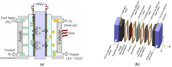
A fuel cell, the core of FCEVs, is an electrochemical system that allows the conversion of the chemical energy stored in hydrogen to electrical energy through a controlled redox reaction. Differently from electrochemical batteries, fuel and oxidants are externally supplied to the system.
Single fuel cell units are composed of [1]:
-
A Membrane electrode assembly (MEA), composed of two electrodes separated by an electrolyte, is used for PEM fuel cells. It is a polymer membrane. The electrodes have different layers: the Catalyst Layer (CL) in direct contact with the electrolyte membrane, followed by a Microporous Layer (MPL) and a Gas Diffusion Layer (GDL), both referred to as diffusion media;
-
Gasket: hydrogen is a very small molecule, and the fuel cell environment is particularly harsh; therefore, specific elastomers must be used to avoid gas leakage [2];
-
Bipolar plates: thanks to their geometry, they allow the different reactant gases to be fed to the specific electrode. They also have dedicated channels for heat exchange purposes. The bipolar plates enable the electrical connection of more fuel cell units for assembling a whole stack.
In the case of a direct hydrogen PEM, hydrogen is supplied at the anode while oxygen is provided at the cathode, just canalizing ambient air; to avoid degradation caused by contaminants, pure hydrogen is needed unless specific technology is used [3].
The reactions occurring at the MEA level are depicted in Figure 1a.
Hydrogen oxidation reaction (HOR) at the anode:
oxygen reduction reaction (ORR) at the cathode:
overall reaction:
Under standard conditions, the maximum voltage thermodynamically reachable with one cell producing water in a liquid state as a by-product is given by the Nernst equation:
where:
-
ΔG is the free Gibbs energy variation (237.2 kJ/mol for the production of liquid water at 25 °C);
-
𝑛 is the number of electrons participating in the reaction;
-
F is the Faraday constant (96,485 C/mol);
-
E0 is the reversible potential of the cell.
Generally, the voltage of a single cell is limited, for physical reasons, to nearly 1 V [4] and is determined as:
where:
-
R is the universal gas constant [J/mol K];
-
T is the temperature in [K];
-
n is the number of transferred electrons;
-
F is the Faraday constant [C/mol];
-
pr is the partial pressure of reactants [bar];
-
pp is the partial pressure of products [bar].
To increase the voltage for common use, a stack of fuel cells may be constructed by connecting multiple units in series [5]. The current collector and end plates complete the stack structure (Figure 1b).
2. Electrolyte
The main functions of PEM are to separate the anode and cathode reactant gases, ensure proton conductivity from anode to cathode and provide electrical insulation between cathode and anode.
For the above reasons, the material must be impermeable to gases, electrically insulating, and have high ionic conductivity. Furthermore, membranes should have sufficient mechanical resistance and be chemically and thermally stable in their operating ranges [8][9].
The state-of-the-art material for automotive applications is perfluoro-sulfonic acid (PFSA). This material has a main hydrophobic perfluorinated chain, which grants mechanical support and chemical stability, and hydrophilic sulfonic acid end-groups, which facilitate water absorption for proton conduction [9]. The length of those side chains influences the stability and performance of the electrolyte. Long-side chain and short-side chain membranes are mainly different in the number of CF2 units [8].
During the operation, (H+) ions diffuse across the membrane in the form of hydronium ions (H3O+) [9][10][11]. The proton conductivity is determined by the membrane hydration: when the membrane is too dry, the ionic conductivity is reduced, determining an increase in the ohmic voltage loss; on the other hand, excessive hydration leads to unwanted membrane flooding that hinders the transport of the reactant gases [8][9]. In standard working conditions, the volume and weight of the membrane increase, respectively, by up to 20% and 50%, due to water uptake from the initial dry condition. The optimum hydration level of the membrane depends on different phenomena such as electro-osmotic drag, back diffusion, water generation, and hydraulic permeation across the electrolyte [9].
Dupont’s Nafion is the most common long-sidechain PFSA for PEMs. Its characteristics show a proton conductivity of 0.13 S/cm at 75 °C and 100% RH, durability above 60,000 h, and high chemical stability [9]. Wang et al. also illustrated the main fabrication methods. An example of a short side-chain material for membranes is Solvay’s Hyflon. Figure 2 reports the chemical structures of Nafion and Hyflon.
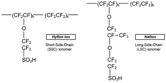
Figure 2. Polymer structures of Hyflon ion/dow, and Nafion [8].
Even if, at present, PFSA is the most commonly used material for PEMs, several drawbacks are still present [5][8][12][13]:
-
Proton conductivity is highly dependent on membrane hydration. This implies the need for accurate humidification control through different strategies (i.e., humidification of reactant gases), which increase system complexity and cost;
-
Temperature limits (around 80 °C) for hydration and mechanical reasons;
-
High production costs;
-
Decomposition of polymer chains due to susceptibility to metallic cations;
-
PEM swell/shrinking during cyclic operation, which can result in membrane failure;
-
Environmentally unfriendly material;
-
Possible degradation of the polymer backbone (–CF2–) for the reaction with hydrogen.
In order to mitigate those problems and extend the operational ranges at low humidity conditions (i.e., 0% RH) and high or low temperatures (i.e., >120 °C), different strategies, reinforcements, or materials have been proposed [8].
Wang et al. [9] provided a review of membrane improvements and production methods, while Wang et al. [8] and Rosli et al. [14] summarized the major alternatives for PEM membrane materials.
A short summary of some interesting solutions is highlighted hereafter: the blend of sulfonated polymers and non-volatile, thermally stable ionic liquids increases ionic conductivity but may decrease mechanical properties; the incorporation of nanoparticles as additives or fillers (graphene oxide, carbon nanotube, silica, polytetrafluoroethylene, ZrO2, TiO2, TiSiO4, etc.) or the use of different materials such as Sulfonated Hydrocarbon Polymers (polysulfones, polyetheretherketones, polybenzimidazoles, etc.) avoids excessive humidification. Additional strategies are the use of thinner membranes to improve humidification (the transport resistance of protons and water is proportional to the membrane thickness), but they are more prone to mechanical damage and degradation, so reinforcement becomes essential; the use of MPLs to increase water retention; and the use of a counterflow configuration of reactant gases, which improves membrane humidification [9][15].
3. Electrodes
3.1. Catalyst Layer
Catalyst Layers (CLs) are the electrode surfaces where electrochemical reactions occur. Their role is to facilitate the reactions along with providing pathways for reactant gas supply, water removal, proton transport towards the membrane, and electron conduction towards the current collector [8][9].
A typical CL is composed of catalyst nanoparticles, usually platinum, adsorbed onto carbon particles as support material and impregnated with ionomer thin films, creating a tortuous void structure with pores [16][17]. The redox reactions take place at these triple-phase boundaries of the CLs [9]. It is essential that the Pt/C powder be mixed with the ionomeric form of the membrane to ensure adequate ionic conduction between CLs and the membrane. There is a precise Pt/C/ionomer equilibrium value: a large quantity of ionomer can reduce the gas diffusion pathways and the contact with the catalyst [18]. Wang et al. [9] determined an optimum Nafion loading of around 30 wt%.
Usually, those blends come in the form of ink/paste that can be deposited either on the membrane or the diffusion media surface. Several methods, such as spraying, screen printing, painting, decaling, rolling, electro-deposition, impregnation reduction, and evaporative deposition, have been used and studied [19].
Even if, due to its high activity, Pt is considered the state-of-the-art material as a PEM catalyst, it has several drawbacks, such as its high cost and poisoning susceptibility to pollutants like CO, which progressively reduce the catalytic performances [5][9][20][21].
Research efforts are focused on improving CO tolerance and reducing the high-cost platinum loading without affecting the durability of the cell using less expensive valuable metals such as ruthenium or palladium, several Pt alloys (Pt-Co, Pt-Ni, Pt-Fe, Pt-V, Pt-Mn, and Pt-Cr) [9], or using cheaper metals [22]. Figure 3 shows the cost and loading targets of platinum catalysts for a 100 kW FCEV, while Table 1 reports the main catalyst alternatives along with their related benefits and drawbacks. For a specific, in-depth analysis, see [5][8][9][17][23][24][25][26][27][28].
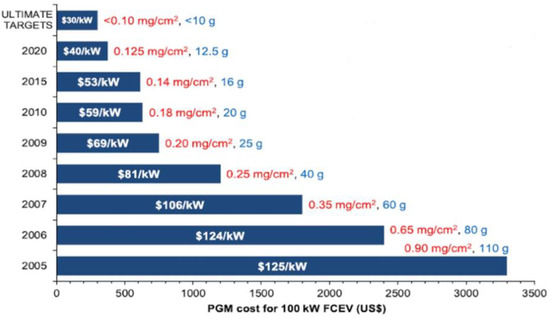
Figure 3. Cost and loading of platinum group metals (PGM) for 100 kW FCEV from 2005 to 2020, based on the current Pt raw price of USD ≈ 30/g. The values inside the bars show the total fuel cell stack cost for a manufacturing volume of 500,000 units per year. The values outside the bars give the total catalyst loading per unit cell area (mg/cm2) and for a 100 kW FCEV (g). Adapted from [5].
Table 1. Benefits and remaining challenges for each of the primary categories of electrocatalysts [8]; ECSA: electrochemical surface area, is the active area of the catalyst where reactions occur. Mass activity is defined as the current at a specified voltage per given mass loading of catalyst; PGM: platinum group metals.
| Catalyst-Type | Benefit | Remaining Challenges |
|---|---|---|
| Platinum | Mature technology. | Unable to meet long-term automotive Pt loading and catalyst layer durability targets. |
| Pt alloy/de-alloy | Mature technology; | Difficult to meet the long-term automotive Pt loading target. |
| Improved performance over Pt/C; | ||
| Enhanced MEA durability. | ||
| Core-shell * | Improved mass activity over Pt alloy; | Difficult to maintain the quality of the shell; |
| Improved durability over Pt/C; | Dissolution of the core is still a concern. | |
| Highest reported ECSA. | ||
| Shape controlled nanocrystal | Significantly higher mass activity (~×15) over Pt; | Scale-up is at an early stage; |
| Chemical synthesis (vs. electrochemical) may allow for easier scale-up vs. core-shell. | Conflicting data on stability; | |
| MEA performances have not been demonstrated yet. | ||
| Nano-frame/nano-cage ** | Significantly higher mass activity (>×20) over Pt; | Scale-up is at an early stage; |
| Highly stable (improved durability over Pt/C). | Ionomer penetration into the nanocage will likely be difficult; | |
| MEA performance at high current density may be challenging. | ||
| Non-precious metal catalyst | Potentially offer the largest benefits (significant cost reduction); | Close to meeting targets for non-automotive applications but far from automotive targets; |
| Tolerant to common contaminants. | At current volumes, PGM loading is not a major concern for non-automotive applications. |
3.2. Diffusion Media
The role of the diffusion media layers is to provide electron conduction between the bipolar plate (BP) and the CL, uniform and direct passage for reactant gas distribution, by-product removal, mechanical support for MEA, and protection of the CL from corrosion and erosion [9]. It must be noted that at the GDL surface, accumulation of water droplets may hinder the reactants flow; therefore, a proper water removal strategy is needed, and the presence of a diffusion media layer is part of it [8].
Carbon paper, made of about 7 μm-diameter fibers aggregated with a binder, is the state-of-the-art material used for GDLs. In order to allow effective water removal, compounds such as Polytetrafluoroethylene (Teflon) are often added to GDL to provide hydrophobic behavior. However, excessive loadings should be avoided; otherwise, the pore volumes will be reduced and gas passage through the pores will be limited. New developments are focusing on metallic and Porous Silicon GDL [9].
A Microporous Layer (MPL) is often inserted between GDL and CL to offer protection for the catalyst, provide a better and smoother physical interface between layers, improve multi-phase contact [9], and improve MEA chemical and mechanical stability [8]. It also has beneficial effects on water management, resulting in reduced ohmic losses (see Zhang et al. [29] for an in-depth study on the influence of MPL on water management). MPL is usually made of carbon black powder bound together with PTFE, which makes MPLs hydrophobic and provides a porous structure with pore dimensions greater than the voids of CLs but smaller than those of the GDL [8][30].
4. Bipolar Plates
BPs positioned after the MEA layers allow the series connection of different cells to form a stack, acting as a current collector and giving mechanical support. Their structure, with three different and separated channelings grooved in the surfaces, supplies reactant gas to each cell as well as the liquid coolant flow. Water removal is performed through the same channels, which should be more hydrophilic than the other layers [8].
The state-of-the-art material for BPs is graphite, which shows good corrosion resistance and good electrical conductivity. On the other hand, graphite is brittle, causing problems during production, and gas permeable, leading to possible leakages [8][9].
Research is exploring several alternative materials, such as carbon composites, which show good electrical and thermal conductivity but weak mechanical robustness, and metals (aluminum, stainless steel, and titanium), which have good mechanical, electrical, thermal properties, and easy machining. In the case of metals, protective coating is needed due to their susceptibility to corrosion, which leads to the formation of oxidants, passive layers, and metal ions that can harm the integrity of the MEA [1][9][31]. Wang et al. [8][9] collect different studies on these new solutions.
Another important aspect is the BP’s flow field (channeling) design. It can influence pressure losses and the uniformity of gas spreading, as well as electrical current and heat transmission. Straight parallel rows, serpentine, pin-type, and interdigitated-type flow fields are the most common designs used in PEM fuel cells (Figure 4). Different studies performed an evaluation of several BP flow field geometries [1][8]:
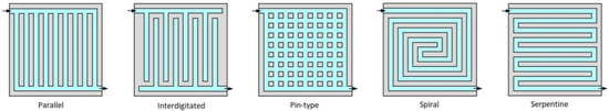
Figure 4. Main flow field designs for bipolar plates [32].
-
Parallel: low pressure drops, homogenous distribution of reactants, low water removal capacity, and voltage instability:
-
Interdigitated: high water removal capacity, homogenous distribution of reactants, and high pressure drops;
-
Pin-type: low pressure drops, low water removal capacity, and uneven distribution of reactants;
-
Spiral: low humidity requirements and high pressure drops;
-
Serpentine: high water removal capacity, uneven distribution of reactants, high pressure drops.
As device power increases, electrode and BP sizes also tend to increase. However, using larger electrodes can lead to problems like uniformity issues in reactions, causing uneven current distribution and potentially forming high-current density hot spots that raise temperature and damage the membrane. This degradation shortens cell and system lifetimes. Hence, BPs must withstand current density variations and be able to distribute appropriate current across the electrodes to counter degradation effects [33].
References
- Basma, H.; Rodríguez, F. Fuel Cell Electric Tractor-Trailers: Technology Overview and Fuel Economy; Working Paper 2022-23; International Council On Clean Transportation: Washington, DC, USA, 2022.
- Lin, C.-W.; Chien, C.-H.; Tan, J.; Chao, Y.-J.; Van Zee, J.W. Dynamic mechanical characteristics of five elastomeric gasket materials aged in a simulated and an accelerated PEM fuel cell environment. Int. J. Hydrogen Energy 2011, 36, 6756–6767.
- Pei, P.; Wang, M.; Chen, D.; Ren, P.; Zhang, L. Key technologies for polymer electrolyte membrane fuel cell systems fueled impure hydrogen. Prog. Nat. Sci. Mater. Int. 2020, 30, 751–763.
- Benmouiza, K.; Cheknane, A. Analysis of proton exchange membrane fuel cells voltage drops for different operating parameters. Int. J. Hydrogen Energy 2018, 43, 3512–3519.
- Aminudin, M.A.; Kamarudin, S.K.; Lim, B.H.; Majilan, E.H.; Masdar, M.S.; Shaari, N. An overview: Current progress on hydrogen fuel cell vehicles. Int. J. Hydrogen Energy 2023, 48, 4371–4388.
- Rezk, H.; Wilberforce, T.; Olabi, A.G.; Ghoniem, R.M.; Sayed, E.T.; Ali Abdelkareem, M. Optimal Parameter Identification of a PEM Fuel Cell Using Recent Optimization Algorithms. Energies 2023, 16, 5246.
- Pourrahmani, H.; Siavashi, M.; Yavarinasab, A.; Matian, M.; Chitgar, N.; Wang, L.; Van herle, J. A Review on the Long-Term Performance of Proton Exchange Membrane Fuel Cells: From Degradation Modeling to the Effects of Bipolar Plates, Sealings, and Contaminants. Energies 2022, 15, 5081.
- Wang, Y.; Seo, B.; Wang, B.; Zamel, N.; Jiao, K.; Adroher, X.C. Fundamentals, materials, and machine learning of polymer electrolyte membrane fuel cell technology. Energy AI 2020, 1, 100014.
- Wang, Y.; Ruiz Diaz, D.F.; Chen, K.S.; Wang, Z.; Adroher, X.C. Materials, technological status, and fundamentals of PEM fuel cells—A review. Mater. Today 2020, 32, 178–203.
- Zelovich, T.; Winey, K.I.; Tuckerman, M.E. Hydronium ion diffusion in model proton exchange membranes at low hydration: Insights from ab initio molecular dynamics. J. Mater. Chem. A 2021, 9, 2448–2458.
- Banerjee, S. Handbook of Specialty Fluorinated Polymers: Preparation, Properties, and Applications; Elsevier William Andrew: Waltham, MA, USA, 2015.
- Automotive News Europe. Daimler Will end Development of Fuel Cell Cars, 22 April 2020. Available online: https://europe.autonews.com/automakers/daimler-will-end-development-fuel-cell-cars (accessed on 24 July 2023).
- Chen, P.; Fang, F.; Zhang, Z.; Zhang, W.; Wang, Y. Self-assembled graphene film to enable highly conductive and corrosion resistant aluminum bipolar plates in fuel cells. Int. J. Hydrogen Energy 2017, 42, 12593–12600.
- Rosli, N.A.H.; Loh, K.S.; Wong, W.Y.; Yunus, R.M.; Lee, T.K.; Ahmad, A.; Chong, S.T. Review of Chitosan-Based Polymers as Proton Exchange Membranes and Roles of Chitosan-Supported Ionic Liquids. Int. J. Mol. Sci. 2020, 21, 632.
- Chen, C.-Y.; Su, J.-H.; Ali, H.M.; Yan, W.-M.; Amani, M. Effect of channel structure on the performance of a planar membrane humidifier for proton exchange membrane fuel cell. Int. J. Heat Mass Transf. 2020, 163, 120522.
- Shao, M.; Chang, Q.; Dodelet, J.-P.; Chenitz, R. Recent Advances in Electrocatalysts for Oxygen Reduction Reaction. Chem. Rev. 2016, 116, 3594–3657.
- Popov, B.N.; Ho, D.; Benjamin, T. V.A.6 Development of Ultra-Low Platinum Alloy Cathode Catalysts for PEM Fuel Cells; FY 2015 Annual Progress Report; Univ. of South Carolina: Columbia, SC, USA, 2015.
- Wang, Y.; Yu, J.; Wu, J.; Wang, Z. Rapid Analysis of Platinum and Nafion Loadings Using Laser Induced Breakdown Spectroscopy. J. Electrochem. Soc. 2017, 164, F1294–F1300.
- Sharma, J.; Lyu, X.; Reshetenko, T.; Polizos, G.; Livingston, K.; Li, J.; Wood, D.L.; Serov, A. Catalyst layer formulations for slot-die coating of PEM fuel cell electrodes. Int. J. Hydrogen Energy 2022, 47, 35838–35850.
- Borup, R.L.; Mukundan, R.; More, K.L.; Neyerlin, K.C.; Weber, A.; Myers, D.J.; Ahluwalia, R. PEM Fuel Cell Catalyst Layer (MEA) Architectures. In Proceedings of the Electrochemical Society Conference, Seattle, WA, USA, 13 May 2018; Available online: https://www.osti.gov/biblio/1440415 (accessed on 24 July 2023).
- Borup, R.L.; More, K.L.; Myers, D.J. FC-PAD: Fuel Cell Performance and Durability Consortium Update to USCAR Analysis of Toyota Mirai Components Provided by USCAR. In Proceedings of the USCAR, Southfield, MI, USA, 11 May 2018; Available online: https://www.osti.gov/servlets/purl/1440417 (accessed on 11 August 2023).
- Jaouen, F.; Jones, D.; Coutard, N.; Artero, V.; Strasser, P.; Kucernak, A. Toward Platinum Group Metal-Free Catalysts for Hydrogen/Air Proton-Exchange Membrane Fuel Cells. Johns. Matthey Technol. Rev. 2018, 62, 231–255.
- Bai, Z.; Huang, R.; Niu, L.; Zhang, Q.; Yang, L.; Zhang, J. A Facile Synthesis of Hollow Palladium/Copper Alloy Nanocubes Supported on N-Doped Graphene for Ethanol Electrooxidation Catalyst. Catalysts 2015, 5, 747–758.
- Haug, A.; Zenyuk, I.; Allen, J.; Lindell, M.; Sun, F.; Abulu, J.; Yandrasits, M.; Thoma, G.; Steinbach, A.; Kurkowski, M.; et al. Novel Ionomers and Electrode Structures for Improved PEMFC Electrode Performance at Low PGM Loadings (Final Report); 3M Company: Maplewood, MN, USA, 2020.
- Pintauro, P. Fuel Cell Membrane-Electrode-Assemblies with Ultra-Low Pt Nanofiber Electrodes. DOE Hydrogen and Fuel Cells Program. Annual Progress Report. 2018. Available online: https://www.hydrogen.energy.gov/pdfs/progress18/fc_pintauro_2018.pdf (accessed on 24 July 2023).
- Wu, G. Current challenge and perspective of PGM-free cathode catalysts for PEM fuel cells. Front. Energy 2017, 11, 286–298.
- Banham, D.; Ye, S. Current Status and Future Development of Catalyst Materials and Catalyst Layers for Proton Exchange Membrane Fuel Cells: An Industrial Perspective. ACS Energy Lett. 2017, 2, 629–638.
- Cui, R.; Mei, L.; Han, G.; Chen, J.; Zhang, G.; Quan, Y.; Gu, N.; Zhang, L.; Fang, Y.; Qian, B.; et al. Facile Synthesis of Nanoporous Pt-Y alloy with Enhanced Electrocatalytic Activity and Durability. Sci. Rep. 2017, 7, 41826.
- Zhang, J.; Wang, B.; Jin, J.; Yang, S.; Li, G. A review of the microporous layer in proton exchange membrane fuel cells: Materials and structural designs based on water transport mechanism. Renew. Sustain. Energy Rev. 2022, 156, 111998.
- Malekian, A.; Salari, S.; Stumper, J.; Djilali, N.; Bahrami, M. Effect of compression on pore size distribution and porosity of PEM fuel cell catalyst layers. Int. J. Hydrogen Energy 2019, 44, 23396–23405.
- Alo, O.A.; Otunniyi, I.O.; Pienaar, H.; Iyuke, S.E. Materials for Bipolar Plates in Polymer Electrolyte Membrane Fuel Cell: Performance Criteria and Current Benchmarks. Procedia Manuf. 2017, 7, 395–401.
- Neto, D.M.; Oliveira, M.C.; Alves, J.L.; Menezes, L.F. Numerical Study on the Formability of Metallic Bipolar Plates for Proton Exchange Membrane (PEM) Fuel Cells. Metals 2019, 9, 810.
- Baumann, N.; Blankenship, A.; Dorn, M.; Cremers, C. Evaluating Current Distribution and Influence of Defect Sites for Graphitic Compound Bipolar Plate Materials. Fuel Cells 2020, 20, 40–47.
More
Information
Subjects:
Transportation Science & Technology
Contributors
MDPI registered users' name will be linked to their SciProfiles pages. To register with us, please refer to https://encyclopedia.pub/register
:
View Times:
921
Revisions:
3 times
(View History)
Update Date:
19 Oct 2023
Table of Contents


Notice
You are not a member of the advisory board for this topic. If you want to update advisory board member profile, please contact office@encyclopedia.pub.
OK
Confirm
Only members of the Encyclopedia advisory board for this topic are allowed to note entries. Would you like to become an advisory board member of the Encyclopedia?
Yes
No
${ textCharacter }/${ maxCharacter }
Submit
Cancel
Back
Comments
${ item }
|
${ item.createdUser.fullName }
${ item.createdAt }
${ item.vote }
${ item.reply }
Delete
${ reply.createdUser.fullName }
${ reply.createdAt }
${ reply.vote }
Delete
There is no reply to this comment~
${ item.replyTextCharacter }/${ item.replyMaxCharacter }
Submit
Cancel
More
No more~
There is no comment~
${ textCharacter }/${ maxCharacter }
Submit
Cancel
${ selectedItem.replyTextCharacter }/${ selectedItem.replyMaxCharacter }
Submit
Cancel
Confirm
Are you sure to Delete?
Yes
No