Your browser does not fully support modern features. Please upgrade for a smoother experience.
Submitted Successfully!
 +1 credit
Thank you for your contribution! You can also upload a video entry or images related to this topic.
For video creation, please contact our Academic Video Service.
| Version | Summary | Created by | Modification | Content Size | Created at | Operation |
|---|---|---|---|---|---|---|
| 1 | Zhidan Zheng | -- | 1511 | 2023-09-05 15:50:58 | | | |
| 2 | Sirius Huang | Meta information modification | 1511 | 2023-09-06 03:01:30 | | |
Video Upload Options
We provide professional Academic Video Service to translate complex research into visually appealing presentations. Would you like to try it?
Cite
If you have any further questions, please contact Encyclopedia Editorial Office.
Zheng, Z.; Li, M.; Tseng, T.; Schlichtmann, U. Wavelength-Routed Optical Networks-on-Chip Topology. Encyclopedia. Available online: https://encyclopedia.pub/entry/48836 (accessed on 25 June 2026).
Zheng Z, Li M, Tseng T, Schlichtmann U. Wavelength-Routed Optical Networks-on-Chip Topology. Encyclopedia. Available at: https://encyclopedia.pub/entry/48836. Accessed June 25, 2026.
Zheng, Zhidan, Mengchu Li, Tsun-Ming Tseng, Ulf Schlichtmann. "Wavelength-Routed Optical Networks-on-Chip Topology" Encyclopedia, https://encyclopedia.pub/entry/48836 (accessed June 25, 2026).
Zheng, Z., Li, M., Tseng, T., & Schlichtmann, U. (2023, September 05). Wavelength-Routed Optical Networks-on-Chip Topology. In Encyclopedia. https://encyclopedia.pub/entry/48836
Zheng, Zhidan, et al. "Wavelength-Routed Optical Networks-on-Chip Topology." Encyclopedia. Web. 05 September, 2023.
Copy Citation
Optical networks-on-chip (NoCs) have emerged as a next-generation solution to overcome the limitations of electrical NoCs. In particular, wavelength-routed optical networks-on-chip (WRONoCs) are well known for their high bandwidth and ultra-low signal delay. Despite these advantages, WRONoCs are challenged by reliability concerns, because the main components in WRONoCs, i.e., microring resonators (MRRs), are susceptible to fabrication inaccuracies. When an MRR along a signal path is defective, the signal transmitted on that path will fail to reach its designated destination, which leads to transmission errors and data loss.
wavelength-routed optical networks-on-chip
fault-tolerant topology
reliability
1. Introduction
Stimulated by recent breakthroughs in silicon photonics, optical networks-on-chip (ONoCs) have emerged as a next-generation solution to overcome the bandwidth and energy limitations of the electrical interconnects in multiprocessor system-on-chip (MPSoC) [1][2]. As the name suggests, ONoCs use optical signals to transmit data [2]. Taking advantage of the wavelength-division multiplexing (WDM) technology and the ultra-low propagation delay of light in silicon, ONoCs promise to meet the high bandwidth demands while maintaining low latency and power [3].
Current ONoC architectures can be classified into two categories: control-networks-based and wavelength-routed [3]. On control-networks-based ONoCs, before a sender (master) can transmit data to a receiver (slave), a signal path needs to be reserved through an additional control network [4][5]. On the other hand, wavelength-routed ONoCs (WRONoCs) fix collision-free signal paths between all master–slave pairs at the time of the design so that all masters can communicate to all slaves simultaneously [6][7][8][9][10]. Therefore, WRONoCs are free from the energy and latency overhead for arbitration and are gaining increasing research interest.
Typically, the WRONoC design is divided into two consecutive steps: a topological and a physical design. A WRONoC topology specifies the interconnection and configuration of the network components, and a physical tool implements the interconnection of the input topology on a layout plane [11]. Figure 1a shows a simple WRONoC topology, where one master sends signals to three slaves. The signals sent from the master are modulated on three different wavelengths, represented by the blue, red, and green arrows. The signals travel along the same waveguide until they are demultiplexed by different optical switching elements (OSEs). Figure 1b shows one typical structure of the 2-input × 2-output OSEs, called a crossing switching element (CSE). A 2 × 2 CSE consists of a pair of orthogonal waveguides and two microring resonators (MRRs) configured to be on-resonance with the wavelength 𝜆𝑖. As shown in Figure 1c, when signals on 𝜆𝑖 enter the CSE, they are coupled to the MRR and experience a 90∘∘ change in their propagation directions. On the other hand, when signals on the wavelengths other than 𝜆𝑖 enter the CSE, they will pass through the CSE and keep their propagation directions, as shown in Figure 1d.
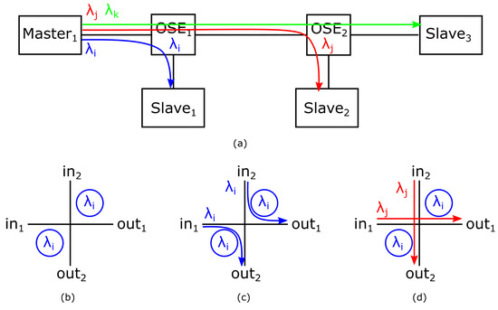
Figure 1. (a) A simple WRONoC topology. (b) A 2 × 2 CSE structure. (c) On-resonance signals change their propagation directions. (d) Off-resonance signals pass through the CSE without direction change.
Due to the complexity of the manufacturing process, MRRs are susceptible to fabrication errors [12][13][14]. Defective MRRs can cause malfunctions and even data loss in WRONoCs, which lowers the fabrication yield. For example, if the MRR in OSE1 shown in Figure 2 is defective and fails to resonate with its designed wavelength 𝜆𝑖, the signal on 𝜆𝑖 will fail to reach Slave1, causing data loss. Therefore, enhancing the reliability of WRONoCs is of great importance.
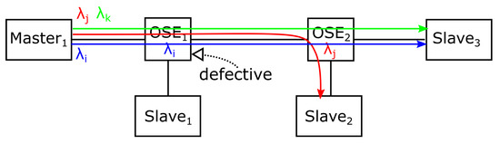
Figure 2. The MRR in OSE1 is defective and the signal on 𝜆𝑖 fails to be coupled to the MRR.
2. Parallel Switching Elements
In ONoCs, OSEs have various structures. Aside from the CSE, shown in Figure 1b, another typical structure of OSEs is called the parallel switching element (PSE). In a PSE, an MRR is placed between a pair of parallel waveguides so that signals entering the PSE will experience a 180-degree direction change [15]. Figure 3 illustrates the working mechanism of a PSE. Compared to the CSE, where two MRRs are placed close to a pair of crossed waveguides, a PSE avoids the crossing loss and crosstalk noise generated by the waveguide crossing and requires only one MRR to route the signals among two inputs and two outputs. Considering these advantages, a PSE is considered as an appealing component to construct WRONoCs [2].
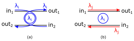
Figure 3. A 2 × 2 PSE supports (a) two on-resonance signals and (b) two off-resonance signals.
3. Performance Factors
In ONoCs, insertion loss and crosstalk noise are two important performance factors, which can decrease the signal-to-noise ratio (SNR) and cause power penalties [16].
Insertion loss is the power loss of signals. Typically, in a WRONoC topology, the insertion loss of a signal can be considered as the summation of three main losses [6][15]: the crossing loss that depends on the number of waveguide crossings that the signal passes; the drop loss when the signal is on-resonance with an MRR; the through loss when the signal passes through an off-resonance MRR. In particular, the worst-case insertion loss of a WRONoC topology is the maximum insertion loss of all signals, which determines the power consumption of the network.
Crosstalk noise refers to the noise signals generated at MRRs and waveguide crossings [16]. As shown in Figure 4, when a signal passes through a waveguide crossing or an off-resonance MRR, or when a signal is on-resonance with an MRR, a portion of the signal power will leak to other outputs and become noise. Noise generated by the original signals is denoted as the first-order noise and has the same wavelength as the original signals [17]. When a noise signal reaches a slave, it will decrease the SNR of the desired signals on the same wavelength. Specifically, the SNR of a signal on wavelength 𝜆𝑖 is calculated as , where denotes the output power of the desired signal, and denotes the power of the noise signals [17]. For the calculation of the SNR, we only consider the first-order noise, since the power of the noise generated by other noise signals is relatively small.
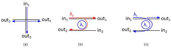
Figure 4. The first-order noise is generated (a) when a signal passes a waveguide crossing, (b) when a signal passes an off-resonance MRR, and (c) when a signal is on-resonance with an MRR.
4. MRR Faults and Signal Faults
An MRR fault can either be temporary or permanent [13]. Temporary faults are caused by environmental changes. For example, a change of 1 ∘C∘C in temperature can shift the resonant wavelength of an MRR by 0.10.1 nnmm, which causes the MRR to resonate with a different wavelength than was intended [13][14]. Some researchers have worked on that problem and proposed some ONoC resilience techniques, such as trimming [18], to correct the faults. On the other hand, permanent faults are caused by fabrication errors. For example, some changes in the physical dimensions, e.g., the radius of the MRRs, the width of the waveguides, and the thickness of the wafer, can affect the resonant wavelengths of the MRRs [14][19]. These permanent faults cannot be corrected by those resilience techniques. Therefore, permanent faults, which can significantly lower the fabrication yield of WRONoCs, should be carefully considered in the design phase, not as an afterthought.
When an MRR is permanently faulty, its resonant wavelength deviates from its designated wavelength, which causes two types of signal faults: stuck-at-zero (s-a-0) and stuck-at-one (s-a-1). The s-a-0 signal fault is that a signal fails to be coupled to the MRR, which is designed to be on-resonance with the signal. As shown in Figure 5a, the MRRs do not resonate with the designated wavelength, and thus the signals cannot be coupled to the MRRs and suffer the s-a-0 faults. On the other hand, a signal suffers an s-a-1 fault when it is coupled to an MRR that is not designated to be on-resonance with the signal. For example, the MRRs designed to resonate with 𝜆𝑖 are now resonant with another wavelength 𝜆𝑗, and the signals on 𝜆𝑗 are coupled to the MRRs as shown in Figure 5b. When a signal suffers either an s-a-0 or s-a-1 fault, it deviates from its planned propagation direction and may fail to reach its designated destination. As a result, the data carried on the signals are lost, which raises the reliability concern of WRONoCs.
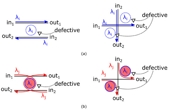
Figure 5. (a) The s-a-0 signal fault. (b) The s-a-1 signal fault.
5. State-of-the-Art WRONoC Topologies
For each master–slave pair that requires communication, state-of-the-art WRONoC topologies construct one fixed signal path [6][15][20][21][22]. In addition, most topologies, such as 𝜆-router [20], Snake [22], and GWOR [21], use CSEs with two identical MRRs, where each MRR is designed to be on-resonance with one signal, which corresponds to one signal path.
Figure 6a shows the logic scheme of a 4×44×4 𝜆-router, which consists of six CSEs. For example, the MRRs of the top-left CSE are on-resonance with the signals from 𝑚1 to 𝑠3 and from 𝑚2 to 𝑠4, respectively.
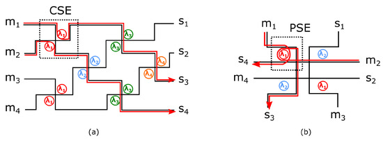
Figure 6. (a) A 4×44×4 𝜆-router. (b) A 4×44×4 Hash.
Figure 6b shows the logic scheme of a 4×44×4 Hash [15], which uses PSEs instead of CSEs. In the Hash, the MRR of a PSE is configured to be on-resonance with two signals. For example, the signals from 𝑚1 to 𝑠4 and from 𝑚2 to 𝑠3, represented by red lines in Figure 6b, are coupled to the MRR of the top-left PSE.
References
- Vantrease, D.; Schreiber, R.; Monchiero, M.; McLaren, M.; Jouppi, N.P.; Fiorentino, M.; Davis, A.; Binkert, N.; Beausoleil, R.G.; Ahn, J.H. Corona: System Implications of Emerging Nanophotonic Technology. ACM Sigarch Comput. Archit. News 2008, 36, 153–164.
- Tseng, T.M.; Truppel, A.; Li, M.; Nikdast, M.; Schlichtmann, U. Wavelength-Routed Optical NoCs: Design and EDA—State of the Art and Future Directions: Invited Paper. In Proceedings of the 2019 IEEE/ACM International Conference on Computer-Aided Design (ICCAD), Westminster, CO, USA, 4–7 November 2019; pp. 1–6.
- Werner, S.; Navaridas, J.; Luján, M. A Survey on Optical Network-on-Chip Architectures. ACM Comput. Surv. 2017, 50, 1–37.
- Xie, Y.; Nikdast, M.; Xu, J.; Zhang, W.; Li, Q.; Wu, X.; Ye, Y.; Wang, X.; Liu, W. Crosstalk Noise and Bit Error Rate Analysis for Optical Network-on-Chip. In Proceedings of the 47th Design Automation Conference (DAC). Association for Computing Machinery, Anaheim, CA, USA, 13–18 June 2010; pp. 657–660.
- Werner, S.; Navaridas, J.; Luján, M. Amon: An Advanced Mesh-like Optical NoC. In Proceedings of the 2015 IEEE 23rd Annual Symposium on High-Performance Interconnects, Santa Clara, CA, USA, 26–28 August 2015; pp. 52–59.
- Li, M.L.; Tseng, T.M.; Bertozzi, D.; Tala, M.; Schlichtmann, U. CustomTopo: A Topology Generation Method for Application-Specific Wavelength-Routed Optical NoCs. In Proceedings of the 2018 IEEE/ACM International Conference on Computer-Aided Design (ICCAD), New York, NY, USA, 5–8 November 2018; pp. 1–8.
- Li, M.; Tseng, T.M.; Tala, M.; Schlichtmann, U. Maximizing the Communication Parallelism for Wavelength-Routed Optical Networks-On-Chips. In Proceedings of the 2020 Asia and South Pacific Design Automation Conference (ASP-DAC), Beijing, China, 13–16 January 2020; pp. 109–114.
- Truppel, A.; Tseng, T.M.; Bertozzi, D.; Alves, J.C.; Schlichtmann, U. PSION: Combining Logical Topology and Physical Layout Optimization for Wavelength-Routed ONoCs. In Proceedings of the 2019 International Symposium on Physical Design (ISPD), San Francisco, CA, USA, 14–17 April 2019; pp. 49–56.
- Truppel, A.; Tseng, T.M.; Bertozzi, D.; Alves, J.C.; Schlichtmann, U. PSION+: Combining Logical Topology and Physical Layout Optimization for Wavelength-Routed ONoCs. IEEE Trans. Comput. Aided Des. Integr. Circuits Syst. 2020, 39, 5197–5210.
- Truppel, A.; Tseng, T.M.; Schlichtmann, U. PSION 2: Optimizing Physical Layout of Wavelength-Routed ONoCs for Laser Power Reduction. In Proceedings of the 39th International Conference on Computer-Aided Design (ICCAD), Virtual, 2–5 November 2020; Association for Computing Machinery: New York, NY, USA, 2020.
- Zheng, Z.; Li, M.; Tseng, T.M.; Schlichtmann, U. ToPro: A Topology Projector and Waveguide Router for Wavelength-Routed Optical Networks-on-Chip. In Proceedings of the 2021 IEEE/ACM International Conference On Computer Aided Design (ICCAD), Munich, Germany, 1–4 November 2021; pp. 1–9.
- Meyer, M.C.; Ahmed, A.B.; Okuyama, Y.; Abdallah, A.B. FTTDOR: Microring Fault-resilient Optical Router for Reliable Optical Network-on-Chip Systems. In Proceedings of the 2015 IEEE 9th International Symposium on Embedded Multicore/Many-core Systems-on-Chip, Turin, Italy, 23–25 September 2015; pp. 227–234.
- Nitta, C.J.; Farrens, M.K.; Akella, V. Resilient Microring Resonator Based Photonic Networks. In Proceedings of the 44th Annual IEEE/ACM International Symposium on Microarchitecture, Porto Alegre, Brazil, 3–7 December 2011; pp. 95–104.
- Meyer, M.; Abdallah, A.B. Fault-tolerant Photonic Network-on-Chip. In Photonic Interconnects for Computing Systems: Understanding and Pushing Design Challenges; River Publishers: Aalborg, Denmark, 2017; pp. 281–318.
- Zheng, Z.; Li, M.; Tseng, T.M.; Schlichtmann, U. Light: A Scalable and Efficient Wavelength-Routed Optical Networks-On-Chip Topology. In Proceedings of the 2021 Asia and South Pacific Design Automation Conference (ASP-DAC), Tokyo, Japan, 18–21 January 2021; pp. 568–573.
- Nikdast, M.; Xu, J.; Duong, L.H.K.; Wu, X.; Wang, X.; Wang, Z.; Wang, Z.; Yang, P.; Ye, Y.; Hao, Q. Crosstalk Noise in WDM-Based Optical Networks-on-Chip: A Formal Study and Comparison. IEEE Trans. Very Large Scale Integr. Vlsi Syst. 2015, 23, 2552–2565.
- Zheng, Z.; Li, M.; Tseng, T.M.; Schlichtmann, U. XRing: A Crosstalk-Aware Synthesis Method for Wavelength-Routed Optical Ring Routers. In Proceedings of the 2023 Design, Automation Test in Europe Conference Exhibition (DATE), Antwerp, Belgium, 17–19 April 2023; pp. 1–9.
- Nitta, C.; Farrens, M.; Akella, V. Addressing system-level trimming issues in on-chip nanophotonic networks. In Proceedings of the 2011 IEEE 17th International Symposium on High Performance Computer Architecture, San Antonio, TX, USA, 12–16 February 2011; pp. 122–131.
- Bogaerts, W.; De Heyn, P.; Van Vaerenbergh, T.; De Vos, K.; Kumar Selvaraja, S.; Claes, T.; Dumon, P.; Bienstman, P.; Van Thourhout, D.; Baets, R. Silicon microring resonators. Laser Photonics Rev. 2012, 6, 47–73.
- Briere, M.; Girodias, B.; Bouchebaba, Y.; Nicolescu, G.; Mieyeville, F.; Gaffiot, F.; O’Connor, I. System Level Assessment of an Optical NoC in an MPSoC Platform. In Proceedings of the 2007 Design, Automation Test in Europe Conference Exhibition (DATE), Nice, France, 16–20 April 2007; pp. 1–6.
- Tan, X.; Yang, M.; Zhang, L.; Jiang, Y.; Yang, J. On a Scalable, Non-Blocking Optical Router for Photonic Networks-on-Chip Designs. In Proceedings of the 2011 Symposium on Photonics and Optoelectronics (SOPO), Wuhan, China, 16–18 May 2011; pp. 1–4.
- Ramini, L.; Grani, P.; Bartolini, S.; Bertozzi, D. Contrasting wavelength-routed optical NoC topologies for power-efficient 3d-stacked multicore processors using physical-layer analysis. In Proceedings of the 2013 Design, Automation Test in Europe Conference Exhibition (DATE), Grenoble, France, 18–22 March 2013; pp. 1589–1594.
More
Information
Subjects:
Engineering, Environmental
Contributors
MDPI registered users' name will be linked to their SciProfiles pages. To register with us, please refer to https://encyclopedia.pub/register
:
View Times:
637
Revisions:
2 times
(View History)
Update Date:
06 Sep 2023
Table of Contents


Notice
You are not a member of the advisory board for this topic. If you want to update advisory board member profile, please contact office@encyclopedia.pub.
OK
Confirm
Only members of the Encyclopedia advisory board for this topic are allowed to note entries. Would you like to become an advisory board member of the Encyclopedia?
Yes
No
${ textCharacter }/${ maxCharacter }
Submit
Cancel
Back
Comments
${ item }
|
${ item.createdUser.fullName }
${ item.createdAt }
${ item.vote }
${ item.reply }
Delete
${ reply.createdUser.fullName }
${ reply.createdAt }
${ reply.vote }
Delete
There is no reply to this comment~
${ item.replyTextCharacter }/${ item.replyMaxCharacter }
Submit
Cancel
More
No more~
There is no comment~
${ textCharacter }/${ maxCharacter }
Submit
Cancel
${ selectedItem.replyTextCharacter }/${ selectedItem.replyMaxCharacter }
Submit
Cancel
Confirm
Are you sure to Delete?
Yes
No