Submitted Successfully!
To reward your contribution, here is a gift for you: A free trial for our video production service.
Thank you for your contribution! You can also upload a video entry or images related to this topic.
Version Summary Created by Modification Content Size Created at Operation
1 -- 9631 2023-08-17 13:05:31 |
2 Reference format revised. Meta information modification 9631 2023-08-21 03:47:18 | |
3 figure captions revised Meta information modification 9631 2023-08-23 02:39:20 |

Video Upload Options

Do you have a full video?

Confirm

Are you sure to Delete?
Cite
If you have any further questions, please contact Encyclopedia Editorial Office.
Choolaei, M.; Fallah Vostakola, M.; Amini Horri, B. Thin-Film Fabrication for Low-Temperature Solid Oxide Fuel Cells. Encyclopedia. Available online: https://encyclopedia.pub/entry/48166 (accessed on 05 May 2024).
Choolaei M, Fallah Vostakola M, Amini Horri B. Thin-Film Fabrication for Low-Temperature Solid Oxide Fuel Cells. Encyclopedia. Available at: https://encyclopedia.pub/entry/48166. Accessed May 05, 2024.
Choolaei, Mohammadmehdi, Mohsen Fallah Vostakola, Bahman Amini Horri. "Thin-Film Fabrication for Low-Temperature Solid Oxide Fuel Cells" Encyclopedia, https://encyclopedia.pub/entry/48166 (accessed May 05, 2024).
Choolaei, M., Fallah Vostakola, M., & Amini Horri, B. (2023, August 17). Thin-Film Fabrication for Low-Temperature Solid Oxide Fuel Cells. In Encyclopedia. https://encyclopedia.pub/entry/48166
Choolaei, Mohammadmehdi, et al. "Thin-Film Fabrication for Low-Temperature Solid Oxide Fuel Cells." Encyclopedia. Web. 17 August, 2023.
Thin-Film Fabrication for Low-Temperature Solid Oxide Fuel Cells
Edit

Solid oxide fuel cells (SOFCs) are amongst the most widely used renewable alternative energy systems with near-zero carbon emission, high efficiency, and environment-friendly features. However, the high operating temperature of SOFCs is still considered a major challenge due to several issues regarding the materials’ corrosion, unwanted reactions between layers, etc. Thus, low-temperature SOFCs (LT-SOFCs) have gained significant interest during the past decades. Despite the numerous advantages of LT-SOFCs, material selection for each layer is of great importance as the common materials have not shown a desirable performance so far. In addition to the selection of the materials, fabrication techniques have a great influence on the properties of the SOFCs. As SOFCs with thinner layers showed lower polarisation resistance, especially in the electrolyte layer, different thin-film fabrication methods have been employed, and their effect on the overall performance of SOFCs has been evaluated.

solid oxide fuel cells low-temperature SOFCs materials selection thin film

1. Introduction

Fuel cells are electrochemical devices that convert chemical energy into electricity with low emissions [1]. Since fuel cells do not have the limitations of internal combustion engines (Carnot cycle), they can generate electricity with higher efficiency [2]. In addition, the progressive increase in utilising hydrogen as a clean energy carrier has caused a great interest in developing more efficient fuel cells as a prospective power source by both research and manufacturing communities. In this regard, fuel cells have already shown great potential in providing electricity for rural areas with no or limited access to the public grid, removing the huge cost of wiring and electricity transfer to these areas [3][4]

According to the choice of fuel and electrolyte, fuel cells are categorised into six major groups: (1) alkaline fuel cell (AFC) [5], (2) phosphoric acid fuel cell (PAFC) [6], (3) solid oxide fuel cell (SOFC) [7], (4) molten carbonate fuel cell (MCFC) [8], (5) proton exchange membrane fuel cell (PEMFC) [9], and (6) direct methanol fuel cell (DMFC) [10]. SOFCs show promising properties compared to other types. SOFCs are among the most promising fuel cells in providing efficient electric power generation and substantial environmental benefits in case of a high level of fuel flexibility. It is this fuel flexibility that has made it possible to operate SOFCs on today’s conventional hydrocarbon fuels, such as methane, methanol, and ethanol [11]. It should be mentioned that anode, cathode, and electrolyte materials differ from one fuel cell technology to another. For example, polybenzimidazole (PBI) and Nafion are the most common membrane materials in PEMFCs, yttria-stabilised zirconia (YSZ), gadolinium-doped ceria (GDC), and lanthanum strontium gallium magnesium oxide (LSGM) are the most common electrolyte materials in SOFCs, molten potassium and lithium carbonate are the most common electrolyte materials in MCFCs, etc. Several anode and cathode materials can also be mentioned for each fuel cell technology, including Ni/GDC, LSCF, lithium metatitanate, porous Ni, and Pt [9][12][13]. Nonetheless, further development is required to overcome some existing limitations surrounding common fuel cell technologies. Reducing cost, improving durability, and further optimising performance have been the focus of most fuel cell research at the individual cell level, stack level, and general system level [14]

Oxygen ions generated at the cathode react with the hydrogen present at the anode side at the junction of electrolyte, electrodes, and pores, so-called triple phase boundaries (TPBs). These redox electrochemical reactions yield the production of heat and water, as well as the release of electrons. Since the electrolyte is not electron-conductive, the generated electrons are pushed towards an external circuit, connecting the anode to the cathode. The flow of electrons in this circuit results in the generation of electrical power. In general, each SOFC is composed of three major components: a dense electrolyte, a porous cathode, and a porous anode [15].
One important factor limiting the development of the SOFC is its high operational temperature. Along with bringing higher operating costs and limiting the choice of material, this matter negatively influences thermochemical stability. In this regard, cell degradation at high operating temperatures is an important technical barrier to the commercialisation of SOFCs, leading to extra costs due to unexpected repair and maintenance [16][17]. Since SOFC scaling up uses repeat cells (so-called “scale-up by number-up”), a single component failure could lead to the failure of the whole stack. In particular, a component failure usually requires the disassembly of the stack to replace it [18][19].
The research addressing low-temperature SOFCs (LT-SOFCs) and intermediate-temperature SOFCs (IT-SOFCs) have focused on different aspects of fuel cells, such as development in material, cell design, and fabrication, as well as fuel selection [20][21][22]. However, most studies have reported a decrease in the SOFC power output by decreasing the operating temperature. It is believed that this behaviour is due to an increase in the ohmic resistance of the electrolyte and the polarisation resistance of both electrodes at lower temperatures [23].
Interfacial resistance between the layers can impede the transport of the reactants and the products, thus limiting the reaction rate. Accordingly, it significantly affects the electrochemical reaction rates, and higher interfacial resistances lead to slower reaction kinetics [24][25]. Regarding the temperature, it may have a negative effect on the temperature distribution within the SOFC. When current flows through the cell, resistive losses occur at the interfaces, resulting in the generation of heat. This resistance-induced heat generation can lead to localised temperature variations and gradients across the cell. If the interfacial resistance is high, more heat will be generated, and localised hotspots may develop. On the other hand, if the interfacial resistance is low, heat generation will be reduced, resulting in a more uniform temperature distribution [25][26]. The temperature of an SOFC is crucial because the electrochemical reactions that occur within the cell are temperature-dependent. 
Low temperatures can affect the oxygen content in solid oxide fuel cells (SOFCs). In an SOFC, oxygen ions (O2−) are transported through the electrolyte material from the cathode to the anode. The rate of oxygen ion conductivity is dependent on temperature, with higher temperatures generally promoting faster ion transport. At lower temperatures, the oxygen ion conductivity decreases, which can impact the overall oxygen content within the cell [27][28]. At low temperatures, the diffusion kinetics of oxygen can be slower. This can affect the rate at which oxygen molecules diffuse to the electrode/electrolyte interfaces, where oxygen reduction and oxidation reactions take place. Slower diffusion kinetics may lead to reduced oxygen availability at the reaction sites, affecting the overall cell performance. 
The electrolyte determines the operating temperature of the SOFCs and is used to prevent the two electrodes from coming into electronic contact by blocking the electrons. However, standard electrolyte materials, based on stabilised zirconia, require that SOFCs are operated at 800–1000 °C to ensure sufficient ionic conductivity and, therefore, output current density. This high temperature causes several issues, such as cell degradation due to thermochemical instability of the electrode constituents, thermal expansion mismatch between the cell’s individual layers, and a higher cost of auxiliary materials (e.g., sealants and interconnects) suitable for such a high temperature [29][30][31]. Therefore, a great deal of interest has been placed on reducing the operating temperature to the range of 400–800 °C. 
Despite the mentioned advantages of LT-and IT-SOFCs, they have not yet found widespread application. The reason for this delay is that, at such low operating temperatures, the increased polarisation losses in the electrodes and low ionic conductivity of the electrolyte make it extremely challenging to maintain high power outputs from the operating cells [32][33]. In addition, in the case of hydrocarbon-fuelled SOFCs, the high rates of carbon deposition and sulphur poisoning in the anode are two important obstacles to overcome when decreasing the operating temperature [27]. Approaches such as decreasing the thickness of conventional YSZ electrolytes and searching for alternative active materials with higher ionic conductivity at lower operating temperatures can be addressed as noteworthy attempts to encounter high ohmic resistance when operating at such temperatures [32].
In parallel, different deposition techniques have been experimentally studied, where novel and cost-effective methods have been developed for the large-scale deposition of thin-film electrolyte layers [34][35]. Since the ohmic resistance is inversely related to the thickness of the electrolyte layer, the first approach would be to decrease the thickness of this layer [36]. A membrane thickness of 1 μm for conventional YSZ could decrease its ohmic resistance to the point that it would be possible to ensure a reasonable power output for a cell operating at 500 °C [37].
Removing the need for external fuel reformers and water–gas shift reactors, especially when using relatively cheap and clean fuels, such as natural gas, has been of great interest for research focused on anode reactions where carbon-containing fuels are used [38][39][40]. In addition, the process of carbon deposition has long been recognised as the main consequence of the internal reforming of hydrocarbon fuels. Thus, it is not surprising that many SOFC studies using hydrocarbon fuels have reported the gradual loss of cell performance due to the vast coverage of anode active sites by carbon compounds, especially when using Ni as part of the anode cermet [38][40]. A common method used in conventional steam reformers to overcome this issue is the use of high steam/carbon (S/C) ratios (e.g., up to 3). However, such high S/C ratios can greatly lower the electrical efficiency of SOFCs by steam dilution of the fuel [39]. In addition, since the steam reforming reaction has an endothermic nature, the unavoidable local cooling points can greatly affect the durability of SOFCs by causing possible mechanical damage to the anode layer [41].

2. Ceramic Processing Techniques

2.1. Thin-Film Fabrication Methods

Since the ohmic resistance is inversely related to the thickness of the electrolyte layer, an important approach for increasing the performance of the cell at LT would be to decrease the thickness of this layer [42]. A membrane thickness of 1 μm for conventional YSZ could decrease its ohmic resistance to a point that it would be possible to ensure a reasonable power output for a cell operating at 500 °C [37][43]. Thus, a great deal of focus has been placed on the development of thin-film electrolytes, as a practical method for moving towards lower operating temperatures. Advanced thin-film fabrication techniques, such as chemical vapor deposition (CVD), physical vapor deposition (PVD), pulsed laser deposition (PLD), aerosol deposition (AD), tape casting, screen printing, and spin coating, have allowed the production of ultra-thin electrolyte layers with thicknesses as low as 10 μm [43]. Some of these techniques are simple and robust, such as screen printing and tape casting, while others offer a higher uniformity and control over the deposited thin layer, such as PVD and CVD. However, neither provides altogether a high deposition rate, low capital cost, smooth and dense layers, durability, and low process temperatures. Considering the targeted objectives of developing LT-SOFCs, having a broader choice of material, and using metallic parts, avoiding high-temperature fabrication techniques is of great importance.

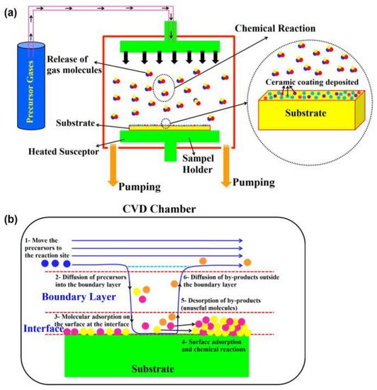
2.1.1. Chemical Vapour Deposition (CVD) Process

CVD has shown growing potential as a nanoscale fabrication technique for SOFCs. In vapor deposition coating processes, vaporised materials are transferred on a substrate in a vapour form. In the CVD method, a chemical reaction is involved in the conversion of vapours to solids. In vapour deposition coating processes, vaporised materials are transferred on a substrate in a vapour form [44][45]. The CVD process can be divided into several categories, including atmospheric pressure CVD (APCVD), low-pressure CVD (LPCVD), ultrahigh-vacuum CVD (UHVCVD), aerosol-assisted CVD (AACVD), metal–organic chemical vapour deposition (MOCVD), and plasma-enhanced CVD (PECVD) [46][47]. In the CVD method, a chemical reaction is involved in the conversion of vapours to solids. During the CVD process, precursors are able to reach the surface of complex structures, providing a relatively uniform layer over the entire surface. In this process, one or more volatile precursors are reacted on the surface of a substrate, forming a thin solid film. This method is extremely sensitive to the applied pressure and temperature conditions [47]. An example of the CVD process is shown in Figure 1a. Generally, the CVD process is divided into six steps according to the temperature, pressure, and heat source. These steps include (a) heat transfer and reactant diffusion to the reaction zone, (b) chemical reaction in the gas phase, (c) transfer of reactants and products to the substrate, (d) chemical adsorption and diffusion of the products on the substrate, (e) formation of the coating on the substrate, and (f) heat transfer and removal of the by-products from the chamber (Figure 1b) [48].
Figure 1. (a) Schematic of CVD technology; (b) main steps of the CVD process [48].
CVD has widely been used in the fabrication of different SOFC layers. Choi et al. [49] employed the AACVD method to fabricate a uniform nanoporous silver surface-treated GDC LT-SOFC cathode with improved power generation and long-term stability compared to the Ag or Pt cathodes. The reason behind this surface treatment was to stabilise the porous structure against thermal aggregation and improve catalytic activity. The higher performance was attributed to the improved kinetics. The highest power density of the SOFC with Ag/GDC cathode was about 62.7 mW·cm−2 at 450 °C (compared to the power density of Pt cathode with a power density of 61.5 mW·cm−2). Jang et al. [50] also used the AACVD process to prepare an anode-supported SOFCS with a dense YSZ electrolyte (1 µm). The cell showed a high power density of about 600 mW·cm−2 at 600 °C. They compared the results with an 8 μm thick YSZ electrolyte produced by screen printing. The results showed that the thinner electrolyte outperformed the one with a thicker one (1.4–4 times more power density). Sakai et al. [51] used the laser chemical vapour deposition (LCVD) technique to deposit a 15 μm dense YSZ thick film electrolyte on a porous Ni/YSZ anode with a low sintering temperature of about 700 °C. However, due to the formation of cracks during the generation tests, the overall performance of YSZ was lower than that of conventional YSZ.
Amongst the different types of CVD techniques, MOCVD attracted a great deal of attention during the past decade, especially in the fabrication of tubular SOFCs. Sawka and Kwatera [52] proposed yttria-doped ceria (YDC) electrolyte using a low-temperature MOCVD process. The results showed a uniform and dense layer in both flat and tubular substrates with good adhesion. They reported that higher pressures resulted in lower gas flow and a thicker diffusion layer. Recently, Sawka [53] also synthesised ScSZ layers on tubular substrates using the MOCVD route in the temperature range of 600–700 °C using Zr(tmhd)4 and Sc(tmhd)3 by optimising the synthesis conditions including Grashof number (Gr), Reynolds number (Re), and distance from the gas flow input (x). The results showed a low value of about 0.01 for the extended Grx/Rex2. In another attempt, Sawka [54] also examined the possibility of using the MOCVD process for depositing a GDC film on tubular SOFCs in the temperature range of 580–800 °C. As the distribution of the thermal and diffusion layer, the boundary layer thickness, and the gradient of static pressure differ from a planar configuration, their results may open a new window for future work in tubular SOFCs.
Overall, the CVD method seems to be an effective method for producing thin-film SOFCs. Different layers with complex compositions can be fabricated using this method. However, one important issue is the mechanical strength of the thin film produced by either this method or other techniques. Further studies need to be conducted to evaluate the mechanical properties of thin films under operation.

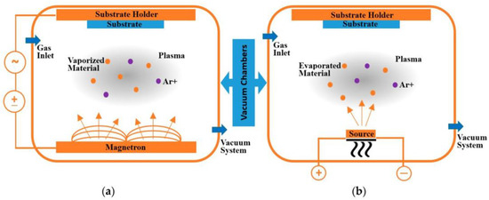
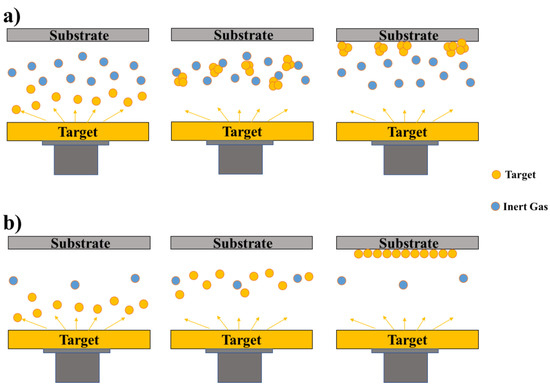
2.1.2. Physical Vapour Deposition (PVD) Process

Unlike CVD, only physical reactions take place in PVD processes. Ideally, the PVD process requires a high vacuum environment for the deposition of a dense and highly pure thin film. However, the process itself can be operated under both low and high vacuum, resulting in different properties for the deposited layer [35][55]. For a flat surface, a film grown using either CVD or PVD may seem similar; however, a considerable difference in the final microstructure of the coated layer can be observed when the deposition is applied to a complex 3D structure. Unlike the CVD process, the PVD of precursors on complex surfaces can result in the agglomeration of the vaporised materials in a certain direction [55]. Thus, depending on the conditions and final requirements, it is essential to use the most suitable method to reach highly stable thin films for SOFCs.
In the PVD thin-film process, the deposited atoms are prepared from a solid material targeted by either a bombardment of energetic gas ions (sputtering) or laser (pulsed laser deposition, PLD) [35]. A typical growth structure of the deposited layer is usually composed of columnar grains; however, this growth pattern can be altered by changing the deposition parameters [55]. Regarding their application in SOFCs, the PVD process has been applied to deposit both porous electrodes and dense electrolytes [56]. Figure 2 illustrates the schematics of different PVD processes.
Figure 2. Schematics of PVD processes: (a) sputter and (b) evaporation using ionised Argon (Ar+) gas [57].
To reach the desired microstructure, crystal structure, and composition ratio for the deposited layer, different parameters such as chamber pressure, power, flow rate, the distance between the target and the substrate, and the substrate temperature must be controlled [58]. Infortuna et al. [59] studied the effect of operating pressure and substrate temperature on the microstructure of YSZ and GDC thin films prepared under PVD conditions. In the study, a microstructural map, as a function of chamber pressure and substrate temperature, was compiled, and required conditions for obtaining porous or dense GDC and YSZ films were reported. Both GDC and YSZ showed the same dependence on pressure and temperature, and it was revealed that an increase in the processing pressure (higher than 0.05 mbar) would result in more porous films. In this pressure range, a fully dense electrolyte structure could not be reached for substrate temperatures below 800 °C. It was suggested that the formation of nanosized agglomerates in the plasma plume at such high pressures along with the high sintering temperatures of both YSZ and GDC would lead to such porous structures (Figure 3a) [55]. To reach full densification at such pressure ranges, substrate temperatures in the range of 1500 °C (sintering temperature) were required. However, decreasing the background pressure to relatively high vacuums (below 0.05 mbar) was shown to have a greater impact on the densification of the electrolyte film (Figure 3b), where the formation of fully dense films was reported at 0.026 mbar and 400 °C [59]. However, when comparing its electrical properties (for both YSZ and GDC thin films) with 10–30 μm films obtained by screen printing and spin coating, relatively higher activation energies and lower conductivities were observed for thin films prepared by the PVD method, mainly due to the loose connection between the electrolyte and the substrate, due to the surface roughness [59][60]. The substrate–target distance and their orientation have also been shown to play an important role in determining the morphology of the coated layer. Changing the substrate–target distance would affect the probability of collision between the background gas molecules and the target material, thus decreasing or increasing the density of the coated layer. In addition, the orientation of the substrate versus the incoming flux of the target material is of high importance, especially when dealing with rough and complex substrate structures [61][62].
Figure 3. Schematics of the effect of (a) increasing and (b) decreasing the chamber pressure on the final structure of the sputtered thin films [55].
The required porosity in the electrodes of SOFCs and the difficulties associated with first fabricating electrolyte layers in the micro-thickness range make the challenge of depositing thin layers of electrolyte on such complex surfaces the key point of PVD processes [63]. Thus, the practical application of such highly conductive thin electrolyte layers is greatly affected by their low density and poor stability when applied over porous electrodes. Successful deposition of dense YSZ thin films over porous Ni/YSZ anodes has been reported in the literature. However, high densities were only applicable over a narrow range of depth and sizes of the surface pores on the substrate [64][65]. Nedelec et al. [63] reported an improved gas tightness and layer morphology for YSZ by applying a different range of radiofrequency bias powers (0.05–0.5 W·cm−2) to a porous anode substrate for SOFCs. It was revealed that increasing the bias power could change the layer growth morphology from columnar to a more packed and uniform isotropic structure, preventing the formation of microcracks. Using Ni/YSZ and lanthanum strontium cobalt ferrite (LSCF) as the anode and the cathode layers, respectively, a performance of 600 mW·cm−2 at 0.7 V and 650 °C was reported (fed with air and H2). One important downside of using bias-assisted sputtering is the observed decrease in the deposition rate, which is already considered the main drawback of using the PVD process for large-scale productions. On the other hand, applying bias assistance can make it possible to reduce the substrate temperature by a few hundred Kelvin, while still achieving a similar result as for unassisted PVD. The latter could be of great benefit by allowing the use of temperature-sensitive substrates for LT-SOFC fabrication [55][66][67].
The deposition rate and target-to-substrate thickness can affect the performance of the solid oxide fuel cell (SOFC) electrolyte. The deposition rate can impact the microstructure and properties of the electrolyte. A high deposition rate may result in a more porous or less dense electrolyte structure, which can affect its ionic conductivity and gas tightness. If the electrolyte is too porous, it may allow unwanted gas leakage or limit the efficiency of ion transport. On the other hand, a low deposition rate can lead to a denser and more uniform electrolyte layer, potentially improving its performance. The thickness of the deposited electrolyte layer is an important parameter that can influence its performance. The target-to-substrate thickness determines the ionic resistance and gas diffusion pathways within the electrolyte. If the electrolyte layer is too thin, it may have a higher ionic resistance, which can hinder ion transport and increase the ohmic losses in the cell. Conversely, if the electrolyte layer is too thick, it can increase the diffusion path length for reactant gases, potentially leading to slower reaction kinetics and reduced cell performance [34][35][68].

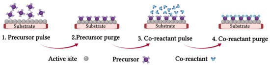
2.1.3. Atomic Layer Deposition (ALD) Process

ALD is basically a modified CVD process in which successive delivery of gas phase precursors is used to reach a surface-limited film growth [69][70]. Unlike the CVD method, where the deposition is applied through a continuous growth process, the ALD technique provides a controlled and stepwise deposition by separating the growth mechanisms into sequential “self-limiting” half-reactions [71][72]. Each ALD cycle usually consists of two surface reactions, in which the thickness of the film is increased by repeating this cycle. When the first precursor is injected into the chamber, it chemisorbs onto the substrate surface, forming one stable monolayer of surface species. In order to continue the growth, a second precursor is introduced to the already purged chamber, while the film growth in this step is also limited to a one-atom layer scale deposition (Figure 4) [73][74]. Thus, in the ALD process, the thickness of the final deposited film is proportional to the number of precursor supply cycles, regardless of the supplied dose of the precursor per cycle. Since the thickness of the deposited layer in each ALD cycle is on the Ångström scale, precise control of the thickness of the layer is often possible. In addition, a high level of film uniformity even along large areas of complex substrates can be reached using the ALD process [75][76].
Figure 4. Schematic of an ALD cycle [74].
The final morphology of an ALD-deposited thin film can be dense, porous, or particulate, depending on the growth stages applied as a function of ALD cycles. Thus, depending on the optimal ALD process, the fabricated layer can be used for different SOFC compounds [43][69]. It should be noted that the development of both CVD and ALD technologies greatly depends on the precursor design processes. Despite the seemingly simple ALD process, achieving this simplicity demands imposing strict requirements on the physical and chemical properties of the precursors. In this regard, the precursors should show enough thermal stability to be transferred to the substrate surface while showing relatively high reactivity with the surfaces of the growing film and the substrate [69][77]. Although the base oxide processes of ZrO2 and Y2O3 for ALD processes have been known for a long time, it was not until 2001–2002 that the optimal ALD processes for the production of pure, smooth, and highly stoichiometric thin layers of these oxides were reported [78][79]. Since then, the successful fabrication of different compositions of YSZ, applying various combinations of Y and Zr precursors and cycle ratios, has been reported. One of the first successful attempts at using ALD YSZ for SOFC applications was reported by Brahim et al. in 2007 [80], where a thin YSZ electrolyte film (300–1000 nm) was deposited on the La0.8Sr0.2MnO3 (LSM) cathode at temperatures as low as 300 °C. Comparing the performance of ALD YSZ and PVD YSZ when applied to the similar cell structures, the ALD process was shown to be able to resolve limitations associated to electrical leakage and fuel permeation of PVD-deposited electrolytes [43][81][82]. Shim et al. [83] reported one of the first fully operating SOFCs using ALD YSZ ultrathin films. A nanoscale 8YSZ electrolyte was deposited between two platinum electrodes, and its performance was evaluated at relatively low operating temperatures (265,300, and 350 °C). The 60 nm thick electrolyte was shown to successfully block both chemical and electric shorts between the electrodes, and relatively high OCVs and peak power densities were achieved, 1.01–1.02 V and 270 mW·cm−2 at 350 °C, respectively.

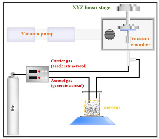
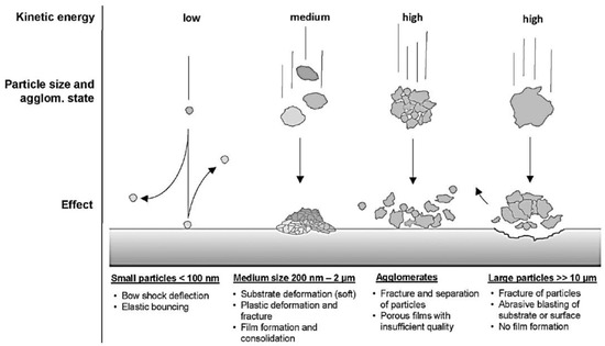
2.1.4. Aerosol Deposition (AD) Process

Aerosol deposition is a coating process in which ultrathin and dense ceramic layers are formed at temperatures as low as room temperature. The deposition process is based on powder consolidation, being the impact adhesion of fine particles. Figure 5 shows the schematics of an AD setup. In this technique, the presence of high-pressure deference between the deposition and aerosol chamber would greatly accelerate the flow of submicron ceramic particles, which are further ejected through a nozzle at a very high speed. The collision of this high-speed flow of particles with the substrate surface leads to the formation of a dense ceramic film [84][85]. Although the detailed mechanism of this process has not yet been clarified, it is known that, during the impact, the kinetic energy of the accelerated particle causes a dramatic increase in the temperature and shock pressure at the point of impact, promoting the binding between the particle and the substrate, in addition to the binding between multiple particles. The high deposition rate (>10 μm/min) and the absence of any further heating processes are the two most important aspects of this process [86][87].
Figure 5. The general schematics of an AD setup [84].
The first published articles based on this coating technique could be traced back to the 1990s when Akedo et al. [88] developed a coating setup called the “jet molding system” (JMS), which was a modified concept for an already existing deposition method called the “gas deposition method” (GDM). The JMS operated under a vacuum and was able to coat a variety of materials on both planar and 3D substrates. Later, Akedo used the term “aerosol deposition” for this coating technique, while most of the early investigations surrounding principles of this room temperature impact consolidation (RTIC) coating method were conducted by Akedo and his group in Japan. Different processing parameters have been suggested to affect the property of the final deposited layer [89][90]. Depending on the material and particle size of the aerosol flow, critical flow velocities are required for the formation of a uniform and dense film. For instance, Akedo et al. suggested a critical velocity of 150 m·s−1 for RTIC of Al2O3 (average particle diameter of 0.3 μm), where the calculated maximum increase in the local temperature and shock pressure due to impact were reported to be 500 °C and 10 GPa, respectively [90][91]. Since such temperature rises were too low to result in local ceramic sintering, Akedo suggested the reduction of crystallite size by fracture and/or plastic deformation to be the reason for the formed dense structures [90].
Figure 6 shows a schematic of possible processes taking place at the point of impact, depending on the particle size and the agglomeration state of the used powders. As shown, particles with very small sizes (lower than 100 nm) would be deflected before reaching the substrate or bounce off after impact. This has been related to the continuous loss in their already low kinetic energy due to the bow shocks and the stagnation point of the flow. Particles with sizes in the range of 200 nm–5 μm are considered to undergo the RTIC mechanism, thus being suitable for the AD method. It should be noted that, although the reported range has been found to be convenient for most materials, it is still related to material properties such as hardness, density, and fracture toughness. Particles larger than 10 μm often lead to abrasive blasting of either the substrate or the film due to their very high kinetic energy on impact. Such behaviour is what is commonly observed in sandblasting, where it is likely for the particles to fracture without showing plastic deformation. Agglomerates of even appropriately sized particles can also disturb the deposition process by absorbing part of the kinetic energy on impact, impeding the RTIC process and resulting in the formation of porous films with reduced adhesion and strength [87][92][93][94].
Figure 6. The impact of the size, speed, and kinetic energy of the ceramic particles on the possible particle–substrate interactions [87].
Due to the widespread use of alumina for different applications, it has been the most frequently studied material for AD processes. Thus, most of the fundamental research on AD mechanisms has been based on this ceramic oxide. An important reported secondary effect of AD alumina layers is the presence of high residual stresses (as high as 2 GPa), which has shown a direct dependence on the type of carrier gas used in the deposition process [92][95]. The presence of such high stresses could result in the formation of cracks and delamination of the thin film, dramatically decreasing its durability if used for SOFC applications. However, using pure oxygen or a mixture of oxygen/inert gas, e.g., O2/He, as the carrier gas for the AD process has been proven to reduce this stress by 50% (for AD alumina films), which a further annealing process at temperatures as low as 300 °C was shown to completely illuminate the residual stress [96]. Therefore, AD alumina thin films with favourable adhesive strength to the substrate have been obtained, possessing excellent anti-scratch, anti-wear, and anti-smudge properties [97][98].

2.1.5. Dip Coating Process

Conventional ceramic processing methods such as dip coating, tape casting, spin coating, and screen printing have been widely used for the fabrication of thin electrolyte films. These relatively simple techniques have been extensively used as cost-effective and flexible fabrication methods in fabricating electrolyte layers with thicknesses as small as a few tens of microns to more than 200 μm. Dip coating, also known as slurry coating, has been used as a simple method to deposit thin electrolyte layers in both planer and tubular SOFCs [99][100][101]. In most wet ceramic coating methods, a slurry consisting of a solvent (i.e., ethanol or an azeotropic mixture of toluene), dispersant (i.e., menhaden fish oil or phosphate ester), binder (i.e., polyvinyl alcohol or polyvinyl butyral), and fin ceramic powder (e.g., YSZ or GDC) is used to coat a porous substrate, e.g., anode or cathode [102]. In this process, the substrate is slowly submerged, kept, and removed from a formulated slurry, where a change in each of these parameters can greatly affect the quality and thickness of the deposited layer (Figure 7a). In the next step, the two-layer substrate is dried at room temperature, preheated at elevated temperature, and sintered. This cycle is commonly repeated 5–10 times or even more, depending on the desired properties of the deposited layer. This method has also been successfully applied for the deposition of thin YSZ electrolyte layers on relatively large porous anode tubes. In this process, the gas tightness and thickness of the deposited layer were closely related to the rate of tube withdrawal from the slurry, the viscosity of the slurry, and the number of coating cycles [103][104][105]. Despite the advantages of this simple and low-cost coating technique, the repetitive cycles of coating–drying–sintering make it a rather time-, energy-, and labour-intensive technique. In addition, the lack of complete control over the film thickness and, often, the presence of picture framing effects, especially near the edges of the substrate, have made this method less attractive for SOFC manufacturing compared to other ceramic processing methods [103][106].
Figure 7. Schematic demonstration of (a) dip coating, (b) tape casting, (c) spin coating [103], and (d) screen printing processes [107].

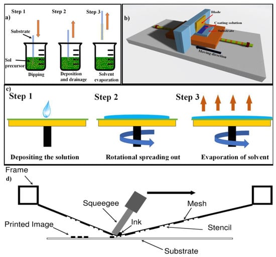
2.1.6. Tape Casting Process

First reported in 1947, tape casting or doctor blade is also a low-cost and simple ceramic processing technique already used to produce large-area zirconia films [108]. This coating process provides attractive features such as (i) forming reproducible layers with uniform structure and thickness, (ii) casting both electrolyte and electrode layers with controllable thicknesses, and (iii) the possibility of mass production when automated. However, it does possess limitations over the thickness of the casted layer (>10 μm) [109]. Compared to spin coating, this process is rather parsimonious, and the losses of the coating solution can be greatly minimised to less than ~5%. Like most wet ceramic processes, slurry preparation is an important step in determining the quality and characteristics of the deposited layer. The slurry preparation commonly includes the dispersion of a certain amount of ceramic powder in a solution consisting of tape-casting additives (such as a binder, dispersant, and plasticisers) and ball milling the mixture [110][111]. Prior to tape casting (Figure 7b), the de-airing process is applied to remove air bubbles trapped in the slurry. Then, the slurry is poured in front of a blade, adjusted at a certain distance from the top of the substrate, enabling a slow linear movement of either the substrate or the blade, and a thin film is formed behind the blade. The coated substrate is then dried and further sintered. In this step, the shrinkage behaviour of the coated layer should be carefully observed to avoid delamination and bending of the bilayer film [103][112][113]. The thickness of the deposited layer can be controlled through the combination of slurry viscosity, linear speed, and doctor blade height [114]. Tape casting can also be used to form the multilayer structure of SOFC, for example, a cell consisting of four layers, two of which are coated by multilayer tape casting and co-sintering (anode and electrolyte layers) [111]. The development of homogenous and agglomerate-free slurries with sufficient viscosity plays a key role in reaching the smooth fabrication of SOFC components through this method [115][116]. Myung et al. [117] reported a characteristic investigation of planar SOFCs fabricated using tape casting. In the study, NiO–YSZ anode-supported half cells were fabricated and coated by thin YSZ electrolyte layers via tape casting. Half cells were co-sintered at 1400 °C and further screen-printed to add the cathode layers. A maximum power density of 0.65 W·cm−2 was reported for the cell operating at 800 °C. Although cofiring the casted layers can improve connectivity between the layers, the high sintering temperature required for the full densification of the electrolyte, especially when YSZ is used, can result in a loss of porosity and homogeneity of the electrode layers. This matter greatly constrains the choice of electrode material and is a common problem observed in most ceramic coating techniques. To solve this problem, sintering aids, e.g., CuO, have been added to the electrolyte slurry, to decrease the co-sintering temperature [118]. While tape casting has proven to be a very cost-effective technique, the relatively low speed of solvent evaporation and large shrinkage associated with the removal of polymeric additives, e.g., binders and plasticisers, during the sintering steps can greatly decrease the quality of the fabricated layer, especially when coating large-area cells (>10 × 10 cm2) [119].

2.1.7. Spin Coating Process

Spin coating is also a simple and cost-effective wet ceramic method used for the fabrication of planar SOFCs. In this method, a formulated slurry is evenly distributed over the substrate surface by the use of centrifugal forces [120]. Figure 7c illustrates a schematic of this coating process [103][121]. This technique offers high reproducibility and allows for the deposition of highly homogenous films over large areas (substrate diameters as high as 30 cm) [122]. A spin coating operation involves applying a slurry on the surface of the substrate followed by the acceleration of the substrate to a set rotational speed. Alternatively, the slurry can also be added while the substrate is spinning. The velocity of the spinning substrate forces the ejection of most of the applied slurry, leaving only a very thin film over the substrate. Despite the seemingly wasteful nature of this process, since a very small volume of the slurry is required to complete each coating cycle (0.1 mL), the loss of such small amounts is not critical, especially at small scales. The number of coating cycles, the spinning speed of the substrate, and slurry viscosity are important technical parameters, affecting the thickness and quality of the resultant layers [123][124][125]. Xu et al. [126] reported the formation of a uniform and crack-free YSZ electrolyte layer using spin coating. Increased coating cycles and reduced spinning speeds were reported to increase the electrolyte thickness, where a minimum speed of 2500 rpm and 20 cycles resulted in the formation of a uniform 10 μm YSZ electrolyte layer. Similar results were reported by Wang et al., where a controlled thickness in the range of 12–36 μm was reported [127]. However, in their study, the presence of gas leakage during cell operation was also stated. This matter emphasises the importance of optimising slurry viscosity and the number of coating cycles in order to reach dense electrolyte layers with adequate thickness. For example, Chen et al. [128] reported the fabrication of a dense and pinhole-free SDC electrolyte layer via a five-cycle spin coating process. In the study, an SDC slurry consisting of toluene, PVB (polyvinyl butyral), and ethanol was used, where, after each coating cycle, the substrate was dried at 500 °C for 30 min. It was observed that each coating cycle successfully covers the cracks or pinholes of the previous coating, leading to a crack-free and dense electrolyte layer with about 10 μm thickness. Depending on the composition of the coating solution, spin coating can also be applied to fabricate porous electrodes on dense electrolyte substrates [129][130], thus making spin coating an efficient and inexpensive coating process for the fabrication of multilayer components of SOFCs with uniform thicknesses. While spin coating has proven to be an extremely useful technique for the fabrication of SOFCs on the laboratory scale, it is still questionable if it can be applied for large-scale production of SOFCs, in particular with respect to its ink/slurry usage.

2.1.8. Screen Printing Process

Screen printing has been shown to be a simple, inexpensive, and flexible method widely used for the fabrication of thin planar SOFC films with thicknesses in the range of 10–100 μm [131][132]. In this method, a screen-printing frame, consisting of a patterned mesh with certain specifications, is placed at a certain distance from the top of a substrate. Then, a squeegee is used to wipe a well-homogenised ink/paste over the screen, pushing the ink through the aperture of the mesh onto the substrate (Figure 14d). Finally, the printed film is dried and sintered at high temperatures to reach rigid films. Generally, the thickness and the final quality of the printed films are greatly affected by both process variables (e.g., printing speed, geometry and angle of the squeegee, mesh parameters, and snap-off distance) and, most importantly, the viscosity and rheology of the formulated ink [107][133][134]. In addition to the ceramic powder, the ink usually consists of a dispersant, a binder, and a solvent, while variation in each of these components can greatly affect the characteristics and the quality of the printed film [110][121][133]. A suitable formulation for the ink can greatly prevent the bleeding or arbitrary spreading of the ink over the printed layer, as well as inhibit the formation of defects (e.g., pinholes) on the sintered electrolyte layer [135]. In order to break down possible, solid agglomerates and reach a high level of homogeneity, the formulated ink is commonly milled using a three-roll mill prior to the screen printing process [121][133].
After reaching the desired rheological properties for the fabricated ink, certain process parameters can then be adjusted to produce high-quality films. However, despite the importance of these parameters, especially when producing very thin electrolyte layers, only a small number of studies have correlated these process parameters with the final properties of the sintered films. A squeegee speed, load/pressure, and angle of 20–50 mm·s−1, 5–9 kg, and 45°, respectively, were recommended in most studies, whereas a snap-off of 1.5–2 mm was shown to result in relatively low film thicknesses [136][137]. These parameters can be further adjusted depending on the ink properties. Mϋcke et al. [137] reported the fabrication of thin YSZ films in the range of 23–100 μm by using a snap-off of 2.0 mm and squeegee pressure and speed of 150 mm·s−1 and 0.3 MPa, respectively. In a similar study, Dollen et al. [138] studied the effect of squeegee speed and hardness on the final properties of YSZ thin films using ink with 40 vol.% of solid content. The results indicated the presence of gaps between the printed YSZ and Ni/YSZ substrate upon using hard squeegees (80 durometers) at high speeds (5.58 cm·s−1). This was related to insufficient print coverage under such conditions. It was further suggested that reduced squeegee speeds provide more time for the ink to flow through the mesh and reach the substrate surface, being extremely important when dealing with inks with high solid content. In addition, the use of softer squeegees tends to decrease the printing angle, increasing the print coverage by forcing more ink through the mesh [107][139]. More work is still required to establish a direct correlation between the ink properties and printer parameters, significantly reducing manufacturing costs and improving film quality.
Overall, screen printing can be considered a promising method for the large-scale production of SOFCs. However, it can only be applied on planer SOFC configurations and possesses similar limitations to the tape casting method, requiring high sintering temperatures (especially when YSZ and GDC are used) and showing large shrinkage levels associated with the removal of organic additives. Thus, it is commonly used for electrode fabrication, where an improved porosity is required.

2.2. Other Fabrication Methods

2.2.1. Solid-State Reaction

It is well known that different synthesis processes can greatly alter the microstructure of the products, resulting in changes in (a) the grain size and grain boundaries in the electrolyte, and (b) the durability and electrochemically active surface area of the electrodes [140][141]. In addition, the number of impurities observed in different SOFC components is also closely dependent on the synthesis and fabrication procedures used. Thus, the activation energy and electrical conductivity can be greatly affected by different procedures, as impurity levels significantly alter the characteristics of the grain boundary, grain, and density levels. The solid-state reaction is a well-known preparation method for its high yield, high selectivity, simplicity, and the absence of numerous solvents and side reactions. This method requires intimate mixing of the ceramic compounds in the form of oxides or other forms such as carbonates, where repetitive cycles of grinding and heating are commonly applied in order to reach a complete reaction between all reagents [142][143]. However, it requires a long process time and can lead to high contamination levels. In addition, due to the large number of uncertain factors involved in multiphase reactions, the final structure and composition of the samples are often inhomogeneous and nonstoichiometric [144].
When compared with data obtained with other methods, lower electrolyte conductivities, and much higher activation energies were reported for samples prepared using a solid-state reaction [145][146]. Zhan et al. [147] studied the contribution of grain boundary resistance to the total resistance measured for electrolytes produced through this method and reported an overwhelming contribution of more than 90%, resulting in low total conductivities. It was further reported that it is the presence of high levels of impurities in the grain boundaries of samples prepared through solid-state processing that blocked oxygen ion migration in the electrolyte structure. In addition, high temperatures required for the annealing processes during solid-state reactions commonly result in the formation of strongly agglomerated particles with large particle sizes [148]. Thus, very high sintering temperatures are often required for the full densification of the resulting electrolyte powder. Such high sintering temperatures can be extremely problematic when the electrolyte is co-fired with the electrode material [149]. As was mentioned in the previous section, it is often required for a thin electrolyte layer to be supported on an electrode substrate in order to improve cell performance by decreasing the ohmic resistance of the electrolyte layer [42]. In such configurations, the prepared electrode-electrolyte bilayers are co-fired to reach a dense electrolyte film while preserving the electrode porosity [150]. High sintering temperatures required for electrolyte powders prepared by the solid-state reaction can either lead to extreme interfacial reactions between the electrode and electrolyte materials or a loss in the electrode porosity [42]. Both of which are fatal for the fuel cell performance. Thus, alternative preparation methods, such as wet chemical methods, have been proposed in order to overcome such drawbacks.

2.2.2. Sol–Gel Process

The sol–gel chemical synthesis method has also been used as a useful wet chemical route for laboratory synthesis of ceramic oxides [151]. Since, during a wet chemical reaction, the precursors are commonly dissolved and mixed in a solution, it is possible to reach a high level of homogeneity in the final product. Thus, by using the sol–gel method, it is possible to obtain stoichiometric ceramic powders at relatively low temperatures, avoiding problems aroused from solid-state reactions. However, numerous properties need to be controlled to reach superior properties for produced ceramics when compared to solid-state processing [152][153]. Sol–gel synthesis is an increasingly popular wet chemical synthesis method, first adopted for the synthesis of glass materials and novel compositions of ceramic oxides in the 1960s [154]. However, numerous properties need to be controlled to reach superior properties for produced ceramics when compared to solid-state processing [152][155][156]. The synthesis process includes the transition of monomers from a solution or colloidal liquid system (sol) into an integrated solid network (gel) [157]. The formed gel is basically a solid-state network in a liquid. In general, the synthesis process can be characterised by the following steps: (1) the formation of stable solutions of the solvated metal precursors (the sol); (2) gel formation resulting from the formation of an alcohol- or oxide-bridged network (the gel), commonly through polycondensation reactions. The initiation of such reactions can be observed in the form of a dramatic increase in the viscosity of the solution; (3) Gel ageing, where a solid mass is gradually formed. During this step, the continuous polycondensation reaction contracts the gel network, also expulsing the solvent from the gel pores; (4) drying the gel by removing water and other volatile liquids from the gel network; (5) decomposition and densification of the dried gel at high temperatures. Such processes would result in the formation of smaller particles with improved sinterability [158].
An important advantage of the sol–gel process or, in general, wet chemical processes is the possibility of incorporating different types of dopants at different stages of the process, where, due to the mixing of the precursors at the molecular level, an enhanced distribution of the dopant in the final solid solution can be achieved [159]. Thus, a greater grain interior conductivity can be reached for the electrolyte layer. Although the properties of materials synthesised through sol–gel processes are commonly superior to solid-state reactions, the relatively low powder yield observed for the sol–gel process limits its use in small-scale productions [21]. In addition, there have been cases where even lower conductivities and higher activation energies were reported for samples prepared using the sol–gel process in comparison to solid-state reactions [147][160][161]. Haung et al. [160] reported the synthesis of Ce0.2Sm0.8O1.9 using the sol–gel process and investigated the structure, thermal properties, and ionic conductivity of the solid electrolyte. The electrolyte powder revealed a lower sintering temperature (1400 °C) than powders prepared by solid-state processes (1650 °C). In the study, a considerably low conductivity (5.0 × 10⁻³ S·cm−1) and high activation energy (0.97 eV) were reported for the Ce0.2Sm0.8O1.9 sample prepared using the sol–gel process (at 600 °C). Similar observations were also reported for GDC powders prepared using the sol–gel process, where a conductivity and activation energy of 3.6 × 10⁻³ S·cm−1 and 1.08 eV, respectively, were reported for Gd0.1Ce0.9O1.95 [162]. Since such high activation energies and low conductivities are not expected for samples prepared using the sol–gel process, most studies have addressed this issue to the possible presence of impurities in the precursors and solvents used in the process. However, due to the considerable number of similar observations reported by different groups, especially for the synthesis of doped ceria, a more detailed investigation seems to be required.

2.2.3. Coprecipitation Process

The coprecipitation process is a well-known wet chemical method used in the earliest syntheses of nanoparticles, and it is based on the simultaneous precipitation of multiple species [163][164][165][166]. In this method, metal cations can be coprecipitated in different forms, e.g., carbonates, bicarbonates, and oxalates, followed by calcination and decomposition steps. The required calcination step will, however, result in particle agglomeration, which, at relatively high temperatures, could lead to aggregation and sintering. Fortunately, nanoparticulates of carbonate and oxalate have been shown to decompose at relatively low temperatures, minimising the level of agglomeration of the final powder [167][168][169][170]. Both carbonate and oxalate coprecipitation methods have been proven to produce highly sinteractive and homogeneous products and show improved performance over samples prepared using the solid-state reaction and sol–gel techniques [171][172], especially when used for the synthesis of doped ceria [168][170]. However, different problems, such as relatively low green density (for oxalate) and composition deviation from feed ratios (for carbonate), limit their application as an ideal synthesis method for SOFC applications [171].
In the oxalate coprecipitation synthesis process, oxalate acid (C2H2O4) is commonly used to react with the present metal cations in the solution, forming fine precipitates. The precipitates are then calcined to obtain the desired metal oxide composition. Generally, oxalate precipitates show good stability towards different treatment conditions, such as washing and drying, and possess a relatively high production yield [173]. In addition, the high homogeneity of the electrolyte powders produced by this method commonly results in the report of high bulk conductivities [170]. Such observations can be traced back to the early applications of this method for the production of doped ceria-based electrolyte powders [174]. Nevertheless, samples prepared using the oxalate coprecipitation method do require higher sintering temperatures when compared to other wet chemical methods, i.e., carbonate coprecipitation [175]. It has been seen that the oxalate coprecipitation method usually results in the formation of large rod-like particles, being the agglomerates of smaller irregular-shaped particles. Thus, electrolytes prepared using this method illustrate relatively low green densities and commonly require high sintering temperatures in order to reach full densification [176][177][178].
The carbonate synthesis route is similar to a coprecipitation method where ammonium carbonate is commonly used as the precipitant. Carbonates are known as precursors for highly sinterable oxides [168]. The non-gelatinous nature of carbonate precursors allows for low agglomeration of the resultant powders, resulting in well-distributed nano-sized particles with relatively low sintering temperatures [179]. Thus, most of the literature surrounding the carbonate coprecipitation method is mainly focused on the aspects of microstructure and sinterability, whereas a smaller number of studies address its effect on the electrical properties of the synthesised samples. Although the reported conductivity data for electrolytes prepared by carbonate precipitation show a slight inconsistency, especially for doped ceria, high conductivities and considerably low activation energies are often reported [180][181][182]. Tok et al. [183] reported a conductivity of 18.3 × 10⁻³ S·cm−1 (600 °C) for Gd0.1Ce0.9O1.95, while even higher conductivities of 22 × 10−3 S·cm−1 (600 °C) have been reported for Sm0.2Ce0.8O1.9 prepared using carbonate coprecipitation [184]. Both studies revealed activation energies lower than 0.7 eV. Nanosized spherical-shaped particles with high surface areas are usually reported for powders prepared by the carbonate method [182][185]. Such microstructural properties have been proven to facilitate the sinterability of the synthesised electrolyte powders, making it possible to reach high densification levels at relatively low temperatures [186]. In addition, low sintering temperatures offer the possibility of fabricating thin electrolyte layers with submicron grain sizes which can greatly enhance the grain boundary conductivity of the electrolyte layer, especially for doped ceria solid electrolytes.

2.2.4. Glycine Nitrate Process (Combustion)

Recently, the development of novel combustion preparation processes has made it possible to produce ultrafine ceramic oxide powders at a surprisingly low reaction time and calcination temperatures with improved powder characteristics. The method includes an exothermic redox reaction between suitable oxidisers (e.g., metal nitrates) and an organic fuel (e.g., glycine, urea, and citric acid) [42][187][188][189]. In this synthesis process, important characteristics such as surface area, crystallite size, and the nature of the agglomerates can be controlled by the flame temperature and level of generated gaseous products, which in turn show great dependence on both the nature of the fuel and the oxidant-to-fuel ratio [190][191][192]. In general, all fuels used in this synthesis process serve two purposes: (1) acting as the H and C source, whereupon combustion forms H2O, CO2, and liberated heat; (2) forming complexes with the metal ions, improving the homogeneous mixing of metal cations in the final product [193]. When compared to conventional synthesis techniques, the combustion method provides attractive advantages. First, the relatively high heat generated from the redox reaction can greatly decrease the need for a rather energy-intensive high-temperature furnace, commonly used as an external energy source for conventional synthesis methods. Furthermore, this simple method is capable of producing ultrafine ceramic powders with very high purity [188][194]. The generated high temperature purges the powder of any possible volatile impurities present in the reactants. The combination of high-temperature gradients with rapid cooling rates in the generated combustion wave can result in the formation of unique microstructures, making it possible to produce powders with small average particle sizes and high porosity [188][190][194]. In addition, the rapid formation of large volumes of gaseous products generated in this method greatly dissipates the combustion heat, limiting the temperature rise and, therefore, preventing premature particle sintering between primary particles [195]. Furthermore, the gas evolution limits the formation of hard agglomerates by reducing the interparticle contacts, thus improving the sinterability of the final product [196]. Compared to solid-state and sol–gel processes, combustion reactions occur at high temperatures, typically in the range of several hundred to several thousand degrees Celsius. These high temperatures are necessary to initiate and sustain the exothermic reactions involved in combustion. While combustion processes typically involve the rapid oxidation of a fuel source, such as hydrocarbons, in the presence of oxygen, and the temperature required for combustion depends on the specific fuel and the nature of the combustion reaction, controlled reactions and phase transformation are the main characteristics of solid-state reactions [189][197]. On the other hand, the sol–gel process, in which hydrolysis and condensation take place at relatively lower temperatures ranging from room temperature to a few hundred degrees Celsius, enables controlling the composition, structure, and morphology of the product [158]. Regarding fuel cell application, combustion processes are not typically utilised directly in fuel cell applications or materials synthesis due to their high temperatures and rapid, uncontrolled nature. However, the heat generated from combustion reactions can be harnessed to generate high-temperature steam or thermal energy for fuel cell systems [198]. Solid-state processes are commonly employed in fuel cell materials syntheses, such as the fabrication of ceramic electrolytes or electrodes. The high temperatures used in solid-state processes enable the formation of dense, crystalline structures with optimised properties for fuel cell operation [146][199][200]. Sol–gel processes are particularly relevant in fuel cell applications for the production of thin films and nanoscale materials. They provide precise control over composition, morphology, and surface properties, allowing for the development of advanced fuel cell components with improved performance and stability [154][201][202].
Glycine (NH2CH2COOH), with an amino group at one end and a carboxylic acid group at the other end, has been commonly used as a complexing agent when reacted with different metal ions [192]. It is this zwitterionic characteristic of the molecule that allows for an efficient mixture of a variety of metal ions with different ionic sizes. Such characteristics can greatly inhibit selective precipitation among the reactive elements, greatly improving the homogeneity of the metal composites. In addition, glycine can act as a reliable fuel in the combustion reaction when oxidised by nitrate ions [203][204]. A great deal of research has reported the rapid and simple production of single- or multicomponent oxide ceramic powders using the glycine nitrate process [205]. The rapid and self-sustaining nature of glycine nitrate combustion reaction has made it possible to immediately produce homogeneous composite powders with relatively high surface area and very low carbon residue [206][207].
It is often claimed that a well-adjusted stoichiometry can result in an almost complete reaction, where the gaseous combustion products would mostly consist of CO2, N2, and H2O [208]. However, due to the fast reaction rates and, thus, the possible limitations imposed on the reaction kinetics, it is more likely that the combustion processes end up with incomplete reactions [209]. In fact, Pine et al. [210] reported a relatively high emission level of NOx and CO for a wide range of fuel-to-oxidant ratios used in this method. Despite such disadvantages, this synthesis technique has proven to be very successful for the laboratory-scale production of ceria-based SOFCs. Figure 8a,b illustrate a highly porous foam-like GDC particle using the glycine nitrate process before and after calcination. The powder was reported to possess an extremally porous structure with loosely agglomerated particles. Such properties have made it possible to prepare thin doped ceria films (<20 μm) using dry pressing, where the resulting powders were pelletised using hardened metal dies (Figure 7c,d) [197]. When compared with the carbonate precipitation method, lower conductivities have been reported for electrolyte material, especially doped ceria, prepared using the glycine nitrate process [197][211]. Despite the differences between the conductivity values reported by different groups, it can be generally said that electrolyte powders, especially doped ceria, prepared using the coprecipitation and glycine methods show higher conductivity and lower activation energy than samples prepared using the solid-state and sol–gel techniques.
Figure 8. (a) SEM image of as-prepared GDC powder; (b) NiO-GDC powders calcined at 1000 °C; cross-section SEM image of the cell structure, along with N–-GDC anode layers fabricated using glycine nitrate process (c,d) [197].

References

  1. Ilbas, M.; Kumuk, B. Numerical Modelling of a Cathode-Supported Solid Oxide Fuel Cell (SOFC) in Comparison with an Electrolyte-Supported Model. J. Energy Inst. 2019, 92, 682–692.
  2. Li, R.; Peng, L.; Wang, X.; Yang, J.; Yan, D.; Pu, J.; Chi, B.; Li, J. Investigating the Performance of Glass/Al2O3 Composite Seals in Planar Solid Oxide Fuel Cells. Compos. Part B Eng. 2020, 192, 107984.
  3. Baldi, F.; Wang, L.; Pérez-fortes, M.; Maréchal, F. A Cogeneration System Based on Solid Oxide and Proton Exchange Membrane Fuel Cells With Hybrid Storage for Off-Grid Applications. Front. Energy Res. 2019, 6, 139.
  4. Vostakola, M.F.; Salamatinia, B.; Horri, B.A. A Review on Recent Progress in the Integrated Green Hydrogen Production Processes. Energies 2022, 15, 1209.
  5. Wang, J.; Zhang, X.; Li, Y.; Liu, P.; Chen, X.; Zhang, P.; Wang, Z.; Liu, X. Sweet Drinks as Fuels for an Alkaline Fuel Cell with Nonprecious Catalysts. Energies 2021, 14, 206.
  6. Abderezzak, B. Introduction to Hydrogen Technology. In Introduction to Transfer Phenomena in PEM Fuel Cell; ISTE Press-Elsevier: London, UK, 2018; pp. 1–51.
  7. Study, A.F.; Hu, H.; Zou, J.; Shan, L.; Jiang, X.; Ni, Y.; Li, X.; Qian, X. Conductivities in Yttrium-Doped Barium Zirconate: A First-Principles Study. Crystals 2023, 13, 401.
  8. Recirculation, G.; Bian, J.; Duan, L.; Yang, Y. Simulation and Economic Investigation of CO2 Separation from Gas Turbine Exhaust Gas by Molten Carbonate Fuel Cell with Exhaust Gas Recirculation and Selective Exhaust Gas Recirculation. Energies 2023, 16, 3511.
  9. Hooshyari, K.; Amini Horri, B.; Abdoli, H.; Fallah Vostakola, M.; Kakavand, P.; Salarizadeh, P. A Review of Recent Developments and Advanced Applications of High-Temperature Polymer Electrolyte Membranes for PEM Fuel Cells. Energies 2021, 14, 5440.
  10. Rabissi, C.; Zago, M.; Bresciani, F.; Gazdzicki, P.; Casalegno, A. A Novel Accelerated Stress Test for a Representative Enhancement of Cathode Degradation in Direct Methanol Fuel Cells. Energies 2023, 16, 3226.
  11. Weber, A. Fuel Flexibility of Solid Oxide Fuel Cells. Fuel Cells 2021, 21, 440–452.
  12. Ng, K.H.; Rahman, H.A.; Somalu, M.R. Review: Enhancement of Composite Anode Materials for Low-Temperature Solid Oxide Fuels. Int. J. Hydrogen Energy 2019, 44, 30692–30704.
  13. Das, S.; Dutta, K.; Nessim, G.D.; Kader, M.A. Introduction to Direct Methanol Fuel Cells. In Direct Methanol Fuel Cell Technology; Elsevier: Amsterdam, The Netherlands, 2020; pp. 1–12. ISBN 9780128191583.
  14. Ali, M.; Hassan, W.; El Haj, M.; Allagui, A.; Cha, S.W. On the Technical Challenges a Ff Ecting the Performance of Direct Internal Reforming Biogas Solid Oxide Fuel Cells. Renew. Sustain. Energy Rev. 2019, 101, 361–375.
  15. Taroco, H.A.; Santos, J.A.F.; Domingues, R.Z.; Matencio, T. Ceramic Materials for Solid Oxide Fuel Cells. In Advances in Ceramics-Synthesis and Characterization, Processing and Specific Applications; Sikalidis, C., Ed.; IntechOpen: Minas Gerais, Brazil, 2011; pp. 423–446.
  16. Pianko-Oprych, P.; Jaworski, Z.; Kendall, K. Cell, Stack and System Modelling. In High-temperature Solid Oxide Fuel Cells for the 21st Century; Academic Press: Cambridge, MA, USA, 2016; pp. 407–460. ISBN 9780124104532.
  17. Zhang, J.; Lenser, C.; Menzler, N.H.; Guillon, O. Comparison of Solid Oxide Fuel Cell (SOFC) Electrolyte Materials for Operation at 500 °C. Solid State Ionics 2020, 344, 115138.
  18. Wang, J. Barriers of Scaling-up Fuel Cells: Cost, Durability and Reliability. Energy 2015, 80, 509–521.
  19. Wang, J. System Integration, Durability and Reliability of Fuel Cells: Challenges and Solutions. Appl. Energy 2017, 189, 460–479.
  20. Ding, D.; Li, X.; Lai, Y.; Liu, M. Enhancing SOFC Cathode Performance by Surface Modification through Infiltratio. Energy Environ. Sci. 2014, 7, 552–575.
  21. Bi, L.; Traversa, E. Synthesis Strategies for Improving the Performance of Doped-BaZrO3 Materials in Solid Oxide Fuel Cell Applications. J. Mater. Res. 2014, 29, 1–15.
  22. Munira, S.; Hafiz, M.; Othman, D.; Rahman, M.A.; Jaafar, J.; Ismail, A.F.; Li, K. Recent Fabrication Techniques for Micro-Tubular Solid Oxide Fuel Cell Support: A Review. J. Eur. Ceram. Soc. 2015, 35, 1–22.
  23. Jiang, S.P. Development of Lanthanum Strontium Cobalt Ferrite Perovskite Electrodes of Solid Oxide Fuel Cells—A Review. Int. J. Hydrogen Energy 2019, 44, 7448–7493.
  24. Huang, N.; Han, B.; Wang, Y.; Li, Y.; Su, Y.; Guan, W.; Zhou, X.; Chai, M.; Singhal, S.C. On the Dependence of Interfacial Resistance on Contact Materials between Cathode and Interconnect in Solid Oxide Fuel Cells. Int. J. Hydrogen Energy 2021, 46, 20078–20086.
  25. He, S.; Jiang, S.P. Electrode/Electrolyte Interface and Interface Reactions of Solid Oxide Cells: Recent Development and Advances. Prog. Nat. Sci. Mater. Int. 2021, 31, 341–372.
  26. Santoni, F.; Silva Mosqueda, D.M.; Pumiglia, D.; Viceconti, E.; Conti, B.; Boigues Muñoz, C.; Bosio, B.; Ulgiati, S.; McPhail, S.J. In-Situ Study of the Gas-Phase Composition and Temperature of an Intermediate-Temperature Solid Oxide Fuel Cell Anode Surface Fed by Reformate Natural Gas. J. Power Sources 2017, 370, 36–44.
  27. Su, H.; Hu, Y.H. Progress in Low-Temperature Solid Oxide Fuel Cells with Hydrocarbon Fuels. Chem. Eng. J. 2020, 402, 126235.
  28. Liu, J.; Zhu, C.; Zhu, D.; Jia, X.; Zhang, Y.; Yu, J.; Li, X.; Yang, M. High Performance Low-Temperature Solid Oxide Fuel Cells Based on Nanostructured Ceria-Based Electrolyte. Nanomaterials 2021, 11, 2231.
  29. Zarabi, S.; Imran, M.; Lund, P.D. A Review on Solid Oxide Fuel Cell Durability: Latest Progress, Mechanisms, and Study Tools. Renew. Sustain. Energy Rev. 2022, 161, 112339.
  30. Prakash, B.S.; Pavitra, R.; Kumar, S.S.; Aruna, S.T. Electrolyte Bi-Layering Strategy to Improve the Performance of an Intermediate Temperature Solid Oxide Fuel Cell: A Review. J. Power Sources 2018, 381, 136–155.
  31. Afzal, M.; Raza, R.; Du, S.; Lima, R.B.; Zhu, B. Synthesis of Ba0.3Ca0.7Co0.8Fe0.2O3-δ Composite Material as Novel Catalytic Cathode for Ceria-Carbonate Electrolyte Fuel Cells. Electrochim. Acta 2015, 178, 385–391.
  32. Eric, D. Wachsman; Kang Taek Lee Lowering the Temperature of Solid Oxide Fuel Cells. Science 2011, 334, 928–935.
  33. Gao, Z.; Mogni, L.; Miller, E.C.; Railsback, J.; Barnett, S.A. A Perspective on Low-Temperature Solid Oxide Fuel Cells. Energy Environ. Sci. 2016, 9, 1602–1644.
  34. Coddet, P.; Liao, H.; Coddet, C. A Review on High Power SOFC Electrolyte Layer Manufacturing Using Thermal Spray and Physical Vapour Deposition Technologies. Adv. Manuf. 2014, 2, 212–221.
  35. Liang, F.; Yang, J.; Zhao, Y.; Zhou, Y.; Yan, Z.; He, J.; Yuan, Q.; Wu, J.; Liu, P.; Zhong, Z.; et al. A Review of Thin Film Electrolytes Fabricated by Physical Vapor Deposition for Solid Oxide Fuel Cells. Int. J. Hydrogen Energy 2022, 47, 36926–36952.
  36. Horri, B.A.; Selomulya, C.; Wang, H. Electrochemical Characteristics and Performance of Anode-Supported SOFCs Fabricated Using Carbon Microspheres as a Pore-Former. Int. J. Hydrogen Energy 2012, 37, 19045–19054.
  37. Kharton, V.V.; Marques, F.M.B.; Atkinson, A. Transport Properties of Solid Oxide Electrolyte Ceramics: A Brief Review. Solid State Ionics 2004, 174, 135–149.
  38. Lamy, C.; Millet, P. A Critical Review on the Definitions Used to Calculate the Energy Efficiency Coefficients of Water Electrolysis Cells Working under near Ambient Temperature Conditions. J. Power Sources 2020, 447, 227350.
  39. Welaya, Y.M.A.; Mosleh, M.; Ammar, N.R. Thermodynamic Analysis of a Combined Gas Turbine Power Plant with a Solid Oxide Fuel Cell for Marine Applications. Int. J. Nav. Archit. Ocean Eng. 2013, 5, 529–545.
  40. Ouyang, T.; Zhao, Z.; Lu, J.; Su, Z.; Li, J. Waste Heat Cascade Utilisation of Solid Oxide Fuel Cell for Marine Applications. J. Clean. Prod. 2020, 275, 124133.
  41. Micoli, L.; Russo, R.; Coppola, T.; Pietra, A. Performance Assessment of the Heat Recovery System of a 12 MW SOFC-Based Generator on Board a Cruise Ship through a 0D Model. Energies 2023, 16, 3334.
  42. Fallah Vostakola, M.; Amini Horri, B. Progress in Material Development for Low-Temperature Solid Oxide Fuel Cells: A Review. Energies 2021, 14, 1280.
  43. Shina, J.W.; Go, D.; Kye, S.H.; Leea, S.; An, J. Review on Process-Microstructure-Performance Relationship in ALD- Engineered SOFCs. J. Phys. Energy 2019, 1, 042002.
  44. Frishberg, I. V Gas-Phase Method of Metal Powder Production. In Handbook of Non-Ferrous Metal Powders; Elsevier Ltd.: Yekaterinburg, Russia, 2019; Volume 1, pp. 187–200. ISBN 9780081005439.
  45. Sarangan, A. Nanofabrication. In Fundamentals and Applications of Nanophotonics; Woodhead Publishing: Dayton, OH, USA, 2016; pp. 149–184. ISBN 9781782424642.
  46. Igumenov, I.K.; Lukashov, V. V Modern Solutions for Functional Coatings in CVD Processes. Coatings 2022, 12, 1265.
  47. Carlsson, J.; Martin, P.M. Chemical Vapor Deposition. In Handbook of Deposition Technologies for Films and Coatings; William Andrew: Norwich, NY, USA, 2010; pp. 314–363.
  48. Sabzi, M.; Anijdan, S.H.M.; Shamsodin, M.; Farzam, M.; Hojjati-Najafabadi, A.; Feng, P.; Park, N.; Lee, U. A Review on Sustainable Manufacturing of Ceramic-Based Thin Films by Chemical Vapor Deposition (CVD): Reactions Kinetics and the Deposition Mechanisms. coatings 2023, 13, 188.
  49. Choi, H.R.; Neoh, K.C.; Choi, H.J.; Han, G.D.; Jang, D.Y.; Kim, D.; Shim, J.H. Nanoporous Silver Cathode Surface-Treated by Aerosol-Assisted Chemical Vapor Deposition of Gadolinia-Doped Ceria for Intermediate-Temperature Solid Oxide Fuel Cells. J. Power Sources 2018, 402, 246–251.
  50. Jang, D.Y.; Kim, M.; Kim, J.W.; Bae, K.; Son, J.; Schlupp, M.V.F.; Shim, J.H. High Performance Anode-Supported Solid Oxide Fuel Cells with Thin Film Yttria-Stabilized Zirconia Membrane Prepared by Aerosol-Assisted Chemical Vapor Deposition. J. Electrochem. Soc. 2017, 164, F484–F490.
  51. Sakai, T.; Kato, T.; Tanaka, Y.; Goto, T. Preparation of an Yttria-Stabilized Zirconia Electrolyte on a Porous Ni-Based Cermet Substrate by Laser Chemical Vapor Deposition. Mater. Today Commun. 2022, 33, 104169.
  52. Sawka, A.; Kwatera, A. Low Temperature Synthesis of Y2O3–Doped CeO2 Layers Using MOCVD. Mater. Sci. Eng. B 2022, 276, 115580.
  53. Sawka, A. Chemical Vapour Deposition of Scandia-Stabilised Zirconia Layers on Tubular Substrates at Low Temperatures. Materials 2022, 15, 2120.
  54. Sawka, A. MOCVD Growth of Gadolinium Oxide Layers on Tubes. Ceram. Int. J. 2023, 49, 23835–23843.
  55. Lee, Y.H.; Chang, I.; Cho, G.Y.; Park, J.; Yu, W.; Tanveer, W.H.; Cha, S.W. Thin Film Solid Oxide Fuel Cells Operating Below 600 ℃: A Review. Int. J. Precis. Eng. Manuf. Technol. 2018, 5, 441–453.
  56. Zhang, Y.; Knibbe, R.; Sunarso, J.; Zhong, Y.; Zhou, W.; Shao, Z. Recent Progress on Advanced Materials for Solid-Oxide Fuel Cells Operating Below 500 °C. Adv. Mater. 2017, 29, 1700132.
  57. Pinto, G. Sputtering Physical Vapour Deposition (PVD) Coatings: ACritical Review on Process Improvement AndMarket Trend Demands. Coatings 2018, 8, 402.
  58. Seshan, K.; Schepis, D. Handbook of Thin Film Deposition, 4th ed.; Seshan, K., Globalfoundries, D.S., Eds.; William Andrew: Norwich, NY, USA, 2018; ISBN 9780128123126.
  59. Infortuna, B.A.; Harvey, A.S.; Gauckler, L.J. Microstructures of CGO and YSZ Thin Films by Pulsed Laser Deposition. Adv. Funct. Mater. 2008, 18, 127–135.
  60. Coppola, N.; Polverino, P.; Carapella, G.; Ciancio, R.; Rajak, P.; Dario, M.; Martinelli, F.; Maritato, L.; Pianese, C. Large Area Deposition by Radio Frequency Sputtering of Gd0.1Ce0.9O1.95 Buffer Layers in Solid Oxide Fuel Cells: Structural, Morphological and Electrochemical Investigation. Materials (Basel) 2021, 14, 5826.
  61. Mattox, D.M. Handbook of Physical Vapor Deposition (PVD) Processing, 2nd ed.; William Andrew: Norwich, NY, USA, 2010; ISBN 9780815520375.
  62. Lamas, J.S.; Leroy, W.P.; Depla, D. Influence of Target–Substrate Distance and Composition on the Preferential Orientation of Yttria-Stabilized Zirconia Thin Films. Thin Solid Films 2012, 520, 4782–4785.
  63. Nédélec, R.; Uhlenbruck, S.; Sebold, D.; Haanappel, V.A.C.; Buchkremer, H.; Stöver, D. Dense Yttria-Stabilised Zirconia Electrolyte Layers for SOFC by Reactive Magnetron Sputtering. J. Power Sources 2012, 205, 157–163.
  64. Vafaeenezhad, S.; Hanifi, A.R.; Laguna-bercero, M.A.; Etsell, T.H. Microstructure and Long-Term Stability of Ni–YSZ Anode Supported Fuel Cells: A Review To. Mater. Futur. 2022, 1, 042101.
  65. Hanifi, A.R.; Shinbine, A.; Etsell, T.H. Development Of Monolithic YSZ Porous and Dense Layers through Multiple Slip Casting for Ceramic Fuel Cell Applications. Int. J. Appl. Ceram. Technol. 2012, 9, 1011–1021.
  66. Fonseca, F.C.; Uhlenbruck, S.; Nédélec, R.; Sebold, D.; Buchkremer, H.P. Temperature and Bias Effects on Sputtered Ceria Diffusion Barriers for Solid Oxide Fuel Cells. J. Electrochem. Soc. 2010, 157, B1515–B1519.
  67. Ostadi, A.; Hosseini, S.H.; Fordoei, M.E. The Effect of Temperature and Roughness of the Substrate Surface on the Microstructure and Adhesion Strength of EB-PVD ZrO2-%8wtY2O3 Coating. Ceram. Int. 2020, 46, 2287–2293.
  68. Tanhaei, M.; Mozammel, M. Yttria-Stabilized Zirconia Thin Film Electrolyte Deposited by EB-PVD on Porous Anode Support for SOFC Applications. Ceram. Int. 2017, 43, 3035–3042.
  69. Shim, J.H.; Han, G.D.; Choi, H.J.; Kim, Y.; Xu, S.; An, J.; Kim, Y.B.; Graf, T.; Schladt, T.D.; Gür, T.M.; et al. Atomic Layer Deposition for Surface Engineering of Solid Oxide Fuel Cell Electrodes. Int. J. Precis. Eng. Manuf.-Green Technol. 2019, 6, 629–646.
  70. Lee, S.; Lee, Y.; Park, J.; Yu, W.; Cho, G.Y.; Kim, Y.; Cha, S.W. Effect of Plasma-Enhanced Atomic Layer Deposited YSZ Inter-Layer on Cathode Interface of GDC Electrolyte in Thin Film Solid Oxide Fuel Cells. Renew. Energy 2019, 144, 123–128.
  71. Shin, J.W.; Oh, S.; Lee, S.; Yu, J.G.; Park, J.; Go, D.; Yang, B.C.; Kim, H.J.; An, J. Ultrathin Atomic Layer-Deposited CeO2 Overlayer for High-Performance Fuel Cell Electrodes. ACS Appl. Mater. Interfaces 2019, 11, 46651–46657.
  72. Ahn, C.H.; Kim, S.H.; Yun, M.G.; Cho, H.K. Design of Step Composition Gradient Thin Film Transistor Channel Layers Grown by Atomic Layer Deposition. Appl. Phys. Lett. 2014, 105, 223513.
  73. Knoops, H.C.M.; Potts, S.E.; Bol, A.A.; Kessels, W.M.M. Atomic Layer Deposition. In Handbook of Crystal Growth: Thin Films and Epitaxy, 2nd ed.; Elsevier B.V.: Eindhoven, The Netherlands, 2015; pp. 1101–1134. ISBN 9780444633057.
  74. Shahmohammadi, M.; Mukherjee, R.; Sukotjo, C.; Diwekar, U.M.; Takoudis, C.G. Recent Advances in Theoretical Development of Thermal Atomic Layer Deposition: A Review. Nanomaterials 2022, 12, 831.
  75. Shim, J.H.; Choi, H.J.; Kim, Y.; Torgersen, J.; An, J.; Lee, M.H.; Prinz, F.B. Process-Property Relationship in High-K ALD SrTiO3 and BaTiO3: A Review. J. Mater. Chem. C 2017, 5, 8000–8013.
  76. Detavernier, C.; Dendooven, J.; Sree, S.P.; Ludwigc, K.F.; Martens, J.A. Tailoring Nanoporous Materials by Atomic Layer Deposition. Chem. Soc. Rev. 2011, 40, 5242–5253.
  77. Koponen, S.E.; Gordon, P.G.; Barry, S.T. Principles of Precursor Design for Vapour Deposition Methods. Polyhedron 2016, 108, 59–66.
  78. Putkonen, B.M.; Sajavaara, T.; Johansson, L.; Niinistö, L. Low-Temperature ALE Deposition of Y2O3 Thin Films from β-Diketonate Precursors**. Chem. Vap. Depos. 2001, 7, 44–50.
  79. Hausmann, D.M.; Kim, E.; Becker, J.; Gordon, R.G. Atomic Layer Deposition of Hafnium and Zirconium Oxides Using Metal Amide Precursors. Chem. Mater. 2002, 14, 4350–4358.
  80. Cassir, M.; Putkonen, M.; Niinisto, L. Electrical Properties of Thin Yttria-Stabilized Zirconia Overlayers Produced by Atomic Layer Deposition for Solid Oxide Fuel Cell Applications. Appl. Surf. Sci. 2007, 253, 3962–3968.
  81. Kerman, K.; Lai, B.-K.; Ramanathan, S. Nanoscale Compositionally Graded Thin-Film Electrolyte Membranes for Low-Temperature Solid Oxide Fuel Cells. Adv. Energy Mater. 2012, 2, 656–661.
  82. Baek, J.D.; Yu, C.; Su, P. A Silicon-Based Nanothin Film Solid Oxide Fuel Cell Array with Edge Reinforced Support for Enhanced Thermal Mechanical Stability. Nano Lett. 2016, 16, 2413–2417.
  83. Shim, J.H.; Chao, C.-C.; Huang, H.; Prinz, F.B. Atomic Layer Deposition of Yttria-Stabilized Zirconia for Solid Oxide Fuel Cells. Chem. Mater. 2007, 19, 3850–3854.
  84. Lee, C.; Cho, M.-Y.; Kim, M.; Jang, J.; Oh, Y.; Oh, K.; Kim, S.; Park, B.; Kim, B.; Koo, S.-M.; et al. Applicability of Aerosol Deposition Process for Flexible Electronic Device and Determining the Film Formation Mechanism with Cushioning Effects. Sci. Rep. 2019, 9, 2166.
  85. Erilin, I.S.; Agarkov, D.A.; Burmistrov, I.N.; Pukha, V.E.; Yalovenko, D.V.; Lyskov, N.V.; Levin, M.N.; Bredikhin, S.I. Aerosol Deposition of Thin-Film Solid Electrolyte Membranes for Anode-Supported Solid Oxide Fuel Cells. Mater. Lett. 2020, 266, 127439.
  86. Bredikhin, S.I.; Agarkov, D.A.; Agarkova, E.A.; Burmistrov, I.N.; Cherkasov, A.M.; Pukha, V.E.; Yalovenko, D.V.; Lyskov, N.V. Aerosol Deposition as a Promising Technique to Fabricating a Thin-Film Solid Electrolyte of Solid Oxide Fuel Cells. ECS Trans. 2019, 91, 403–413.
  87. Hanft, D.; Exner, J.; Schubert, M.; Stöcker, T.; Fuierer, P.; Moos, R. An Overview of the Aerosol Deposition Method: Process Fundamentals and New Trends in Materials Applications. J. Ceram. Sci. Technol. 2015, 182, 147–182.
  88. Akedo, J.; Ichiki, M.; Kikuchi, K.; Maeda, R. Jet Molding System for Realization of Three-Dimensional Micro-Structures. Sens. Actuators A 1998, 69, 106–112.
  89. Akedo, J.; Lebedev, M. Microstructure and Electrical Properties of Lead Zirconate Titanate (Pb(Zr52/Ti48)O3) Thick Films Deposited by Aerosol Deposition Method. Jpn. J. Appl. Phys. 1999, 38, 5397.
  90. Akedo, J. Room Temperature Impact Consolidation (RTIC) of Fine Ceramic Powder by Aerosol Deposition Method and Applications to Microdevices. J. Therm. Spray Technol. 2008, 17, 181–198.
  91. Furuya, Y.; Tanaka, M.; Kitaoka, S.; Hasegawa, M. Method for Determining Particle Velocity during Aerosol Deposition by Impact Pressure of the Particles. Surf. Coat. Technol. 2022, 443, 128616.
  92. Furuya, Y.; Konuma, S.; Hasegawa, M. Deposition Mechanism of Alumina Particles in Aerosol Deposition Based on the Kinetic Energy of Particles. Surf. Coat. Technol. 2023, 458, 129362.
  93. Kuroyanagi, S.; Shinoda, K.; Yumoto, A.; Akedo, J. Size-Dependent Quasi Brittle–Ductile Transition of Single Crystalline Alpha-Alumina Particles during Microcompression Tests. Acta Mater. J. 2020, 195, 588–596.
  94. Yeganeh, A.Z.; Jadidi, M.; Moreau, C.; Dolatabadi, A. Surface & Coatings Technology Numerical Modeling of Aerosol Deposition Process. Surf. Coat. Technol. 2019, 370, 269–287.
  95. Matsubayashi, Y.; Akedo, J. Aerosol Deposition of Alumina Films on Microstructured Silicon Substrates. Ceram. Int. 2023, 49, 21570–21576.
  96. Schubert, M.; Exner, J.; Moos, R. Influence of Carrier Gas Composition on the Stress of Al2O3 Coatings Prepared by the Aerosol Deposition Method. Materials 2014, 7, 5633–5642.
  97. Seto, N.; Endo, K.; Sakamoto, N.; Hirose, S.; Akedo, J. Hard A-Al2O3 Film Coating on Industrial Roller Using Aerosol Deposition Method. J. Therm. Spray Technol. 2014, 23, 1373–1381.
  98. Lee, W.; Kim, H.; Lee, D.; Jeong, M.; Lim, D.; Nam, S. Al2O3-Nanodiamond Composite Coatings with High Durability and Hydrophobicity Prepared by Aerosol Deposition. Surf. Coat. Technol. 2012, 206, 4679–4684.
  99. Xiao, Y.; Wang, M.; Bao, D.; Wang, Z.; Jin, F.; Wang, Y.; He, T. Performance of Fuel Electrode-Supported Tubular Protonic Ceramic Cells Prepared through Slip Casting and Dip-Coating Methods. Catalysts 2023, 13, 182.
  100. Winter, R.L.; Singh, P.; King, M.K., Jr.; Mahapatra, M.K.; Sampathkumaran, U. Protective Ceramic Coatings for Solid Oxide Fuel Cell (SOFC) Balance-of-Plant Components. Adv. Mater. Sci. Eng. 2018, 2018, 9121462.
  101. Lei, L.; Bai, Y.; Liu, Y. An Investigation on Dip-Coating Technique for Fabricating Anode-Supported Solid Oxide Fuel Cells. Int. J. Appl. Ceram. Technol. 2015, 12, 351–357.
  102. Sahu, S.K.; Panthi, D.; Soliman, I.; Feng, H.; Du, Y. Fabrication and Performance of Micro-Tubular Solid Oxide Cells. Energies 2022, 15, 3536.
  103. Exploration, C.A.B.; Butt, M.A. Thin-Film Coating Methods: A Successful Marriage of High-Quality and Cost-Effectiveness—A Brief Exploration. Coatings 2022, 12, 1115.
  104. Panthi, D.; Tsutsumi, A. A Novel Multistep Dip-Coating Method for the Fabrication of Anode-Supported Microtubular Solid Oxide Fuel Cells. J. Solid State Electrochem. 2014, 18, 1899–1905.
  105. Niazmand, M.; Maghsoudipour, A.; Alizadeh, M.; Khakpour, Z.; Kariminejad, A. Effect of Dip Coating Parameters on Microstructure and Thickness of 8YSZ Electrolyte Coated on NiO-YSZ by Sol-Gel Process for SOFCs Applications. Ceram. Int. 2022, 48, 16091–16098.
  106. Delory, M.; Chorein, B.; Brulez, A.; Mees, L.; Grosjean, N.; Fiorani, T.; Benayoun, S. Role of Surface-Tension Additive in Coating Framing Effect Topography Mathilde. Colloids Surf. A Physicochem. Eng. Asp. 2023, 658, 130554.
  107. Phillips, C.O.; Beynon, D.G.; Hamblyn, S.M.; Davies, G.R.; Gethin, D.T.; Claypole, T.C. A Study of the Abrasion of Squeegees Used in Screen Printing and Its Effect on Performance with Application in Printed Electronics. Coatings 2014, 4, 356–379.
  108. Howatt, G.N.; Breckenridge, R.G.; Brownlow, J.M. Fabrication of Thin Ceramic Sheets for Capacitors. J. Am. Ceram. Soc. 1947, 30, 237–242.
  109. Nishihora, R.K.; Rachadel, P.L.; Quadri, M.G.N.; Hotza, D. Manufacturing Porous Ceramic Materials by Tape Casting—A Review. J. Eur. Ceram. Soc. 2018, 38, 988–1001.
  110. Nie, L.; Sun, Q.; Liu, Z.; Liu, M. Graded Porous Solid Oxide Fuel Cells Fabricated by Multilayer Tape Casting and Co-Firing Progress. Int. J. Hydrogen Energy 2015, 40, 16503–16508.
  111. Lee, S.; Lee, K.; Jang, Y.; Bae, J. Fabrication of Solid Oxide Fuel Cells (SOFCs) by Solvent-Controlled Co-Tape Casting Technique. Int. J. Hydrogen Energy 2017, 42, 1648–1660.
  112. Snowdon, A.L.; Steinberger-wilckens, R. Five-Layer Reverse Tape Casting of IT-SOFC. Int. J. Appl. Ceram. Technol. 2022, 19, 289–298.
  113. Transactions, E.C.S.; Society, T.E. Tubular Solid Oxide Fuel Cells Fabricated by Tape-Casting and Dip-Coating Methods. ECS Trans. 2019, 91, 329–337.
  114. Bulatova, R.; Jabbari, M.; Kaiser, A.; Negra, M.D.; Andersen, K.B.; Gurauskis, J.; Bahl, C.R.H. Thickness Control and Interface Quality as Functions of Slurry Formulation and Casting Speed in Side-by-Side Tape Casting. J. Eur. Ceram. Soc. 2014, 34, 4285–4295.
  115. Aishwarya, K.P.; Darve, R.; Gadde, J.R.; Kale, H. Optimisation of Slurry Compositions for Improving the Mechanical Properties of Low Temperature Co-Fired Ceramic (LTCC) Tapes To. IOP Conf. Ser. 2022, 1248, 012096.
  116. Varghese, J.; Joseph, N.; Jantunen, H. Multilayer Glass–Ceramic/Ceramic Composite Substrates. In Encyclopedia of Materials: Technical Ceramics and Glasses; Elsevier: Oulu, Finland, 2021; Volume 3, pp. 437–451. ISBN 9780128185421.
  117. Myung, J.; Jun, H.; Park, H.; Hwan, M.; Hyun, S. Fabrication and Characterization of Planar-Type SOFC Unit Cells Using the Tape-Casting/Lamination/Co-Firing Method. Int. J. Hydrogen Energy 2011, 37, 498–504.
  118. Santos, T.H.; Grilo, J.P.F.; Loureiro, F.J.A.; Fagg, D.P.; Fonseca, F.C.; Macedo, D.A. Structure, Densification and Electrical Properties of Gd3+ and Cu2+ Co- Doped Ceria Solid Electrolytes for SOFC Applications: Effects of Gd2O3 Content. Ceram. Int. 2018, 44, 2745–2751.
  119. Jabbari, M.; Bulatova, R.; Tok, A.I.Y.; Bahl, C.R.H.; Mitsoulis, E.; Hattel, J.H. Ceramic Tape Casting: A Review of Current Methods and Trends with Emphasis on Rheological Behaviour and Flow Analysis. Mater. Sci. Eng. B 2016, 212, 39–61.
  120. Coduri, M.; Checchia, S.; Longhi, M.; Ceresoli, D. Rare Earth Doped Ceria: The Complex Connection Between Structure and Properties. Front. Chem. 2018, 6, 526.
  121. Mahmud, L.S.; Muchtar, A. Challenges in Fabricating Planar Solid Oxide Fuel Cells: A Review. Renew. Sustain. Energy Rev. 2017, 72, 105–116.
  122. Mishra, A.; Bhatt, N.; Bajpai, A.K. Nanostructured Superhydrophobic Coatings for Solar Panel Applications. In Nanomaterials-Based Coatings; Elsevier Inc.: Jabalpur, India, 2019; pp. 397–424. ISBN 9780128158845.
  123. Yilbas, B.S.; Al-Sharafi, A.; Ali, H. Surfaces for Self-Cleaning. In Self-Cleaning of Surfaces and Water Droplet Mobility; Elsevier: Dhahran, Saudi Arabia, 2019; pp. 45–98. ISBN 9780128147764.
  124. Cui, Z.; Liao, L. Coating and Printing Processes. In Solution Processed Metal Oxide Thin Films for Electronic Applications; Elsevier Inc.: Changsha, China, 2020; pp. 83–97. ISBN 9780128149300.
  125. Zhang, J.X.J.; Hoshino, K. Fundamentals of Nano/ Microfabrication and Scale Effect. In Molecular Sensors and Nanodevices Principles, Designs and Applications in Biomedical Engineering; Academic Press: Cambridge, MA, USA, 2019; pp. 43–111. ISBN 9780128148624.
  126. Xu, X.; Xia, C.; Huang, S.; Peng, D. YSZ Thin Films Deposited by Spin-Coating for IT-SOFCs. Ceram. Int. 2005, 31, 1061–1064.
  127. Wang, J.; Lu, Z.; Chen, K.; Huang, X.; Ai, N.; Hu, J.; Zhang, Y.; Su, W. Study of Slurry Spin Coating Technique Parameters for the Fabrication of Anode-Supported YSZ Films for SOFCs Jiaming. J. Power Sources 2007, 164, 17–23.
  128. Chen, M.; Hee, B.; Xu, Q.; Guk, B.; Ping, D. Fabrication and Performance of Anode-Supported Solid Oxide Fuel Cells via Slurry Spin Coating. J. Memb. Sci. 2010, 360, 461–468.
  129. Yang, Q.; Wang, Y.; Tian, D.; Wu, H.; Ding, Y.; Lu, X.; Chen, Y.; Lin, B. Enhancing Performance and Stability of Symmetrical Solid Oxide Fuel Cells via Quasi-Symmetrical Ceria-Based Buffer Layers. Ceram. Int. 2022, 48, 27509–27515.
  130. Ramasamy, D.; Nasani, N.; Pukazhselvan, D.; Fagg, D.P. Increased Performance by Use of a Mixed Conducting Buffer Layer, Terbia-Doped Ceria, for Nd2NiO4þd SOFC/SOEC Oxygen Electrodes. Int. J. Hydrogen Energy 2019, 44, 31466–31474.
  131. Wu, Y.; Sang, J.; Liu, Z.; Fan, H.; Cao, B.; Wang, Q.; Yang, J.; Guan, W.; Liu, X.; Wang, J. Enhancing the Performance and Stability of Solid Oxide Fuel Cells by Adopting Samarium-Doped Ceria Buffer Layer. Ceram. Int. 2023, 49, 20290–20297.
  132. Feng, Z.; Zhang, X.; Luo, D. Evolution and Effect on Electrolysis Performance of Pores in YSZ Electrolyte Films Prepared by Screen-Printing. Ceram. Int. 2023, 49, 10731–10737.
  133. Baharuddin, N.A. Fabrication of High-Quality Electrode Films for Solid Oxide Fuel Cell by Screen Printing: A Review on Important Processing Parameters. Int. J. Energy Res. 2020, 44, 8296–8313.
  134. Graca, V.C.D.; Holz, L.I.V.; Loureiro, F.J.A.; Mikhalev, S.M.; Fagg, D.P. Ba2NiMoO6-δ as a Potential Electrode for Protonic Ceramic Electrochemical Cells. Int. J. Hydrogen Energy 2023.
  135. Tomašegovi, T. Properties and Colorimetric Performance of Screen-Printed Thermochromic/UV-Visible Fluorescent Hybrid Ink Systems. Appl. Sci. 2021, 11, 11414.
  136. Somalu, M.R.; Yufit, V.; Brandon, N.P. The Effect of Solids Loading on the Screen-Printing and Properties of Nickel/Scandia-Stabilized-Zirconia Anodes for Solid Oxide Fuel Cells. Int. J. Hydrogen Energy 2013, 38, 9500–9510.
  137. Mücke, R.; Büchler, O.; Menzler, N.H.; Lindl, B.; Vaßen, R.; Buchkremer, H.P. High-Precision Green Densities of Thick Films and Their Correlation with Powder, Ink, and Film Properties. J. Eur. Ceram. Soc. 2014, 34, 3897–3916.
  138. Von Dollen, P.; Barnett, S. A Study of Screen Printed Yttria-Stabilized Zirconia Layers for Solid Oxide Fuel Cells. J. Am. Ceram. Soc. 2005, 3368, 3361–3368.
  139. Potts, S.; Phillips, C.; Jewell, E.; Clifford, B.; Lau, Y.C.; Claypole, T. High-Speed Imaging the Effect of Snap-off Distance and Squeegee Speed on the Ink Transfer Mechanism of Screen-Printed Carbon Pastes. J. Coat. Technol. Res. 2020, 17, 447–459.
  140. Na, S.; Tio, B.; Chaou, F.; Bendahhou, A.; Chourti, K.; Jalafi, I.; Yahakoub, E.H.; El Barkany, S.; Abou-salama, M. Optimisation of Electrical Conductivity and Dielectric Properties of Sn4+-Doped (Na0.5Bi0.5)TiO3 Perovskite. Ceram. Int. 2023, 49, 17940–17952.
  141. Kaur, P.; Singh, K. Structural, Morphological and Conducting Properties of Copper and Nickel-Substituted Strontium Manganite. Mater. Today Commun. 2023, 35, 106056.
  142. Kim, D.; Taek, K. Effect of Lanthanide (Ln=La, Nd, and Pr) Doping on Electrochemical Performance of Ln2NiO4+δ−YSZ Composite Cathodes for Solid Oxide Fuel Cells. Ceram. Int. J. 2021, 47, 2493–2498.
  143. Chandrasekaran, R.E.G. Structural, Optical and Magnetic Characterization of Cu-Doped ZnO Nanoparticles Synthesized Using Solid State Reaction Method. J. Mater. Sci. Mater. Electron. 2010, 21, 1168–1173.
  144. Rafique, M.; Nawaz, H.; Rafique, M.S.; Tahir, M.B.; Nabi, G.; Khalid, N.R. Material and Method Selection for Efficient Solid Oxide Fuel Cell Anode: Recent Advancements and Reviews. Int. J. Energy Res. 2019, 43, 2423–2446.
  145. Yang, H.; Wu, N. Ionic Conductivity and Ion Transport Mechanisms Ofsolid-state Lithium-ion Battery Electrolytes: A Review. Energy Sci. Eng. 2022, 10, 1643–1671.
  146. Jiang, S.P. Solid-State Electrochemistry and Solid Oxide Fuel Cells: Status and Future Prospects. Electrochem. Energy Rev. 2022, 5, 5–21.
  147. Zhan, Z.; Wen, T.; Tu, H.; Lu, Z. AC Impedance Investigation of Samarium-Doped Ceria. J. Electrochem. Soc. 2001, 148, 427–432.
  148. Martinelli, H.; Lamas, D.G.; Leyva, A.G.; Sacanell, J. Influence of Particle Size and Agglomeration in Solid Oxide Fuel Cell Cathodes Using Manganite Nanoparticles. Mater. Res. Express 2018, 5, 075013.
  149. Tolchard, J.R.; Grande, T. Chemical Compatibility of Candidate Oxide Cathodes for BaZrO3 Electrolytes. Solid State Ionics 2007, 178, 593–599.
  150. Mehranjani, A.S.; Cumming, D.J.; Sinclair, D.C.; Rothman, R.H. Journal of the European Ceramic Society Low-Temperature Co-Sintering for Fabrication of Zirconia / Ceria Bi-Layer Electrolyte via Tape Casting Using a Fe2O3 Sintering Aid. J. Eur. Ceram. Soc. 2017, 37, 3981–3993.
  151. Mah, J.C.W.; Aznam, I.; Muchtar, A.; Somalu, M.R.; Raharjo, J. Synthesis of (Cu,Mn,Co)3O4 Spinel: Effects of Citrate-to-Nitrate Ratio on Its Homogeneity and Electrical Properties. Energies 2023, 16, 1382.
  152. Lian, Z.; Chen, F.; Song, X.; Liao, D.; Peng, K. Electrochemical Performance of Li13.9Sr0.1Zn(GeO4)4 Prepared by Sol-Gel for Solid Oxide Fuel Cell Electrolyte. J. Alloys Compd. 2021, 882, 160696.
  153. Rivai, A.K.; Shabrina, N.; Setiawan, A.R. Synthesis and Characterization of 8YSZ/5GDC Composite and Dissimiliar-Bulk by Sonochemistry Assisted Sol-Gel Method. J. Phys. Conf. Ser. 2017, 817, 012001.
  154. Cushing, B.L.; Kolesnichenko, V.L.; Connor, C.J.O. Recent Advances in the Liquid-Phase Syntheses of Inorganic Nanoparticles. Chem. Rev. 2004, 104, 3893–3946.
  155. Vostakola, M.F.; Yekta, B.E.; Mirkazemi, S.M. The Effects of Vanadium Pentoxide to Oxalic Acid Ratio and Different Atmospheres on the Formation of VO2 Nanopowders Synthesized via Sol–Gel Method. J. Electron. Mater. 2017, 46, 6689–6697.
  156. Shabani, S.; Naghizadeh, R.; Fallah Vostakola, M.; Golestanifard, F. The Effect of MgO Addition on the Properties of Alumina-Based Ceramic Cores Prepared via Sol–Gel Process. J. Sol-Gel Sci. Technol. 2020, 96, 539–549.
  157. Medina-Ramirez, I.; Hernandez-Ramirez, A.; Maya-Trevino, M.L. Synthesis Methods for Photocatalytic Materials. In Photocatalytic Semiconductors; Springer: Cham, Switzerland, 2015; pp. 69–102. ISBN 9783319109992.
  158. Hossain, S.; Abdalla, A.M.; Noorazean, S.; Jamain, B.; Hj, J. A Review on Proton Conducting Electrolytes for Clean Energy and Intermediate Temperature-Solid Oxide Fuel Cells. Renew. Sustain. Energy Rev. 2017, 79, 750–764.
  159. Navas, D.; Fuentes, S.; Castro-alvarez, A.; Chavez-Angel, E. Review on Sol-Gel Synthesis of Perovskite and Oxide Nanomaterials. Gels 2021, 7, 275.
  160. Huang, W.; Shuk, P.; Greenblatt, M. Properties of Sol-Gel Prepared Ce1-XSmxO2-x/2 Solid Electrolytes. Solid State Ionics 1997, 100, 23–27.
  161. Piñol, S.; Najib, M.; Bastidas, D.M.; Calleja, A.; Capdevila, X.G.; Segarra, M.; Espiell, F.; Ruiz-Morales, J.C.; Marrero-López, D.; Nuñez, P. Microstructure–Conductivity Relationship in Gd- and Sm-Doped Ceria-Based Electrolytes Prepared by the Acrylamide Sol–Gel-Related Method. J. Solid State Electrochem. 2004, 8, 650–654.
  162. Huang, K.; Feng, M.; Goodenough, J.B. Synthesis and Electrical Properties of Dense Ce0.9Gd0.1O1.95 Ceramics Keqin. J. Am. Ceram. Soc. 1998, 62, 357–362.
  163. Choolaei, M.; Jakubczyk, E.; Amini, B. Synthesis and Characterisation of a Ceria-Based Cobalt-Zinc Anode Nanocomposite for Low-Temperature Solid Oxide Fuel Cells (LT-SOFCs). Electrochim. Acta 2023, 445, 142057.
  164. Bellardita, M.; Di Paola, A.; Yurdakal, S.; Palmisano, L. Preparation of Catalysts and Photocatalysts Used for Similar Processes. In Heterogeneous Photocatalysis; Elsevier B.V.: Amsterdam, The Netherlands, 2019; pp. 25–56. ISBN 9780444640154.
  165. Lesani, P.; Babaei, A.; Ataie, A.; Mostafavi, E. Nanostructured MnCo2O4 Synthesized via Co-Precipitation Method for SOFC Interconnect Application. Int. J. Hydrogen Energy 2016, 41, 20640–20649.
  166. Teng, Y.; Zuhairi, A.; Amini, B.; Salamatinia, B. Synthesis and Characterisation of Y2O3 Using Ammonia Oxalate as a Precipitant in Distillate Pack Co-Precipitation Process. Ceram. Int. 2018, 44, 18693–18702.
  167. Liu, S.; Ma, C.; Ma, M.; Xu, F. Magnetic Nanocomposite Adsorbents. In Composite Nanoadsorbents; Elsevier Inc.: Shihezi, China, 2019; pp. 295–316. ISBN 9780128141328.
  168. Agli, G.D.; Spiridigliozzi, L.; Pansini, M.; Accardo, G.; Yoon, S.P.; Frattini, D. Effect of the Carbonate Environment on Morphology and Sintering Behaviour of Variously Co-Doped (Ca, Sr, Er, Pr) Samarium-Doped Ceria in Co- Precipitation/Hydrothermal Synthesis. Ceram. Int. 2018, 44, 17935–17944.
  169. Hui, Y.; Liu, B.; Li, J.; Jun, Y. Improved Energy Storage Performance of Ba0.4Sr0.6TiO3 Nanocrystalline Ceramics Prepared by Using Oxalate Co-Precipitation and Spark Plasma Sintering. Mater. Res. Bull. 2019, 113, 141–145.
  170. Teng, Y.; Zuhairi, A.; Amini, B.; Salamatinia, B. Optimised Co-Precipitation Synthesis Condition for Oxalate-Derived Zirconia Nanoparticles. Ceram. Int. 2019, 45, 22930–22939.
  171. Dong, H.; Koenig, G.M., Jr. A Review on Synthesis and Engineering of Crystal Precursors Produced Via Coprecipitation for Multicomponent Lithium-Ion Battery Cathode Materials. CrystEngComm 2020, 22, 1514–1530.
  172. Pelosato, R.; Cristiani, C.; Dotelli, G.; Mariani, M.; Donazzi, A.; Natali, I.; Leonardo, P. Co-Precipitation Synthesis of SOFC Electrode Materials. Int. J. Hydrogen Energy 2012, 38, 480–491.
  173. Choolaei, M.; Bull, T.; Reina, T.R.; Horri, B.A. Synthesis and Characterisation of Nanocrystalline CuO–Fe2O3/GDC Anode Powders for Solid Oxide Fuel Cells. Ceram. Int. 2020, 46, 14776–14786.
  174. Dokiya, M.; Horita, T.; Kawada, T.; Sakai, N.; Yokokawa, H. Low Temperature Fabrication of (Y,Gd,Sm)-Doped Ceria Electrolyte. Solid State Ionics 1996, 86–88, 1255–1258.
  175. Zha, S.; Xia, C.; Meng, G. Effect of Gd (Sm) Doping on Properties of Ceria Electrolyte for Solid Oxide Fuel Cells. J. Power Sources 2003, 115, 44–48.
  176. Jongen, N.; Bowen, P.; Lemaitre, J.; Valmalette, J.-C.; Hofmann, H. Precipitation of Self-Organized Copper Oxalate Polycrystalline Particles in the Presence of Hydroxypropylmethylcellulose (HPMC): Control of Morphology. J. Colloid Interface Sci. 2000, 226, 189–198.
  177. Huang, J.; Mao, Z.; Liu, Z.; Wang, C. Development of Novel Low-Temperature SOFCs with Co-Ionic Conducting SDC-Carbonate Composite Electrolytes. Electrochem. Commun. 2007, 9, 2601–2605.
  178. Huang, J.; Mao, Z.; Liu, Z.; Wang, C. Performance of Fuel Cells with Proton-Conducting Ceria-Based Composite Electrolyte and Nickel-Based Electrodes. J. Power Sources 2008, 175, 238–243.
  179. Rafique, M.; Safdar, N.; Irshad, M.; Usman, M.; Akhtar, M.; Saleem, M.; Abbas, M.M.; Ashour, A.; Soudagar, M.E. Influence of Low Sintering Temperature on BaCe0.2Zr0.6Y0.2O3−δ IT-SOFC Perovskite Electrolyte Synthesized by Co-Precipitation Method. Materials 2022, 15, 3585.
  180. Fergus, J.; Hui, R.; Xianguo, L.; Wilkinson, D.; Zhang, J. Solid Oxide Fuel Cells: Materials Properties and Performance, 1st ed.; CRC Press: Boca Raton, FL, USA, 2008; ISBN 978-1-4200-8883-0.
  181. Filonova, E.; Medvedev, D. Recent Progress in the Design, Characterisation and Application of LaAlO3- and LaGaO3-Based Solid Oxide Fuel Cell Electrolytes. Nanomaterials 2022, 12, 1991.
  182. Konwar, D.; Nguyen, N.T.Q.; Yoon, H.H. Evaluation of BaZr0.1Ce0.7Y0.2O3-d Electrolyte Prepared by Carbonate Precipitation for a Mixed Ion-Conducting SOFC. Int. J. Hydrogen Energy 2015, 40, 11651–11658.
  183. Tok, A.I.Y.; Luo, L.H.; Boey, F.Y.C. Consolidation and Properties of Gd0.1Ce0.9O1.95 Nanoparticles for Solid-Oxide Fuel Cell Electrolytes. J. Mater. Res. 2006, 21, 119–124.
  184. Ding, D.; Liu, B.; Zhu, Z.; Zhou, S.; Xia, C. High Reactive Ce0.8Sm0.2O1.9 Powders via a Carbonate Co-Precipitation Method as Electrolytes for Low-Temperature Solid Oxide Fuel Cells. Solid State Ionics 2008, 179, 896–899.
  185. Spiridigliozzi, L.; Dell’Agli, G.; Marocco, A.; Accardo, G.; Pansini, M.; Yoon, S.P.; Ham, H.C.; Frattini, D. Engineered Co-Precipitation Chemistry with Ammonium Carbonate for Scalable Synthesis and Sintering of Improved Sm0.2Ce0.8O1.90 and Gd0.16Pr0.04Ce0.8O1.90 Electrolytes for IT-SOFCs. J. Ind. Eng. Chem. 2018, 59, 17–27.
  186. Roy, N.K.; Foong, C.S.; Cullinan, M.A. Effect of Size, Morphology, and Synthesis Method on the Thermal and Sintering Properties of Copper Nanoparticles for Use in Microscale Additive Manufacturing Processes. Addit. Manuf. 2018, 21, 17–29.
  187. Chen, Y.-M.; Lin, T.-N.; Liao, M.-W.; Kuo, H.-Y.; Yeh, C.-Y.; Kao, W.-X.; Yang, S.-F.; Wu, K.-T.; Ishihara, T. Applications of the Glycine Nitrate Combustion Method for Powder Synthesis on the LSGM-Based Electrolyte-Supported Solid Oxide Fuel Cells. ECS Trans. 2017, 78, 773–781.
  188. Jais, A.A.; Ali, S.A.M.; Anwar, M.; Somalu, M.R.; Muchtar, A.; Isahak, W.N.R.W.; Baharudin, N.A.; Lim, K.L.; Brandon, N.P. Performance of Ni/10Sc1CeSZ Anode Synthesized by Glycine Nitrate Process Assisted by Microwave Heating in a Solid Oxide Fuel Cell Fueled with Hydrogen or Methane. J. Solid State Electrochem. 2020, 24, 711–722.
  189. Minakshi, M.; Barmi, M.; Mitchell, D.R.G.; Barlow, A.J.; Fichtner, M. Effect of Oxidizer in the Synthesis of NiO Anchored Nanostructure Nickel Molybdate for Sodium-Ion Battery. Mater. Today Energy J. 2018, 10, 1–14.
  190. Jamale, A.P.; Natoli, A.; Jadhav, L.D. Synthesis of Active Electrocatalysts Using Glycine–Nitrate Chemistry. J. Phys. Chem. Solids 2021, 148, 109723.
  191. Wain-martin, A.; Morán-ruiz, A.; Vidal, K.; Larrañaga, A.; Laguna-bercero, M.A. Scalable Synthetic Method for SOFC Compounds. Solid State Ionics 2017, 313, 52–57.
  192. Komova, O.V.; Mukha, S.A.; Ozerova, A.M.; Odegova, G.V.; Simagina, V.I.; Bulavchenko, O.A.; Ishchenko, A.V.; Netskina, O. V The Formation of Perovskite during the Combustion of an Energy-Rich Glycine–Nitrate Precursor. Materials 2020, 13, 5091.
  193. Patil, K.C.; Aruna, S.T.; Mimani, T. Combustion Synthesis: An Update. Curr. Opin. Solid State Mater. Sci. 2002, 6, 507–512.
  194. Kulkarni, S.; Duttagupta, S.; Phatak, G. Study of Glycine Nitrate Precursor Method for the Synthesis of Gadolinium Doped Ceria (Ce0.8Gd0.2O1.90) as an Electrolyte for Intermediate Temperature Solid Oxide Fuel Cells. RSC Adv. 2014, 4, 46602–46612.
  195. Chen, W.; Li, F.; Yu, J.; Liu, L. A Facile and Novel Route to High Surface Area Ceria-Based Nanopowders by Salt-Assisted Solution Combustion Synthesis. Mater. Sci. Eng. B 2006, 133, 151–156.
  196. Zhang, X.; Jiang, W.; Song, D.; Sun, H.; Sun, Z.; Li, F. Salt-Assisted Combustion Synthesis of Highly Dispersed Superparamagnetic CoFe2O4 Nanoparticles. J. Alloys Compd. 2009, 475, 34–37.
  197. Park, S.-Y.; Na, C.W.; Ahn, J.H.; Song, R.-H.; Lee, J.-H. Preparation of Highly Porous NiO–Gadolinium- Doped Ceria Nano-Composite Powders by One- Pot Glycine Nitrate Process for Anode-Supported Tubular Solid Oxide Fuel Cells. J. Asian Ceram. Soc. 2018, 2, 339–346.
  198. Dong, H.; Wang, M.; Liu, Y.; Han, Z. Optimized Solid-State Synthesis of Sr2Fe1.5Mo0.5O6−δ Perovskite: Implications for Efficient Synthesis of Mo-Containing SOFC Electrodes. Crystals 2022, 12, 1533.
  199. Fan, L. Solid-State Electrolytes for SOFC. In Solid Oxide Fuel Cells: From Electrolyte-Based to Electrolyte-Free Devices; Zhu, B., Raza, R., Fan, L., Sun, C., Eds.; John Wiley & Sons: Hoboken, NJ, USA, 2020; pp. 35–78. ISBN 9783527812790.
  200. Yang, S.H.; Kim, K.H.; Yoon, H.H.; Kim, W.J.; Choi, H.W. Comparison of Combustion and Solid-State Reaction Methods for the Fabrication of SOFC LSM Cathodes. Mol. Cryst. Liq. Cryst. 2011, 539, 50–390.
  201. Kane, N.; Zhou, Y.; Zhang, W.; Ding, Y.; Luo, Z.; Hua, X.; Liu, M. Precision Surface Modification of Solid Oxide Fuel Cells via Layer-by-Layer Surface Sol-Gel Deposition. J. Mater. Chem. A 2022, 10, 8798–8806.
  202. Liu, Y.; Qin, H.; Li, M.; Cheng, J.; Tang, C.; Xiao, J.; Xie, Y. Direct Synthesis of Ce0.8Sm0.2−xZnxO2−δ Electrolyte by Sol–Gel for IT-SOFC. Ionics 2022, 28, 4675–4684.
  203. Tripathi, R.; Dur, L.; Ricardo, P.; Tudela, D.; Christoph, H.; Marx, D. Unveiling Zwitterionization of Glycine in the Microhydration Limit. ACS Omega 2021, 6, 12676–12683.
  204. Aruna, S.T.; Mukasyan, A.S. Combustion Synthesis and Nanomaterials. Curr. Opin. Solid State Mater. Sci. 2008, 12, 44–50.
  205. Birol, H.; Rambo, C.R.; Guiotokuc, M.; Hotza, D. Preparation of Ceramic Nanoparticles via Cellulose- Assisted Glycine Nitrate Process: A Review. RSC Adv. 2013, 3, 2873–2884.
  206. Yu, C.; Sakthinathan, S.; Lai, G.; Lin, C.; Chiu, T.-W.; Liu, M.-C. ZnO–ZnCr2O4 Composite Prepared by a Glycine Nitrate Process Method and Applied for Hydrogen Production by Steam Reforming of Methanol. RSC Adv. 2022, 12, 22097–22107.
  207. Cheng, H.-H.; Chen, S.-S.; Liu, H.-M.; Jang, L.-W.; Chang, S.-Y. Glycine–Nitrate Combustion Synthesis of Cu-Based Nanoparticles for NP9EO Degradation Applications. Catalysts 2020, 10, 1061.
  208. Varma, A.; Mukasyan, A.S.; Rogachev, A.S.; Manukyan, K. V Solution Combustion Synthesis of Nanoscale Materials. Chem. Rev. 2016, 116, 14493–14586.
  209. Stojanovic, B.D.; Dzunuzovic, A.S.; Ilic, N.I. Review of Methods for the Preparation of Magnetic Metal Oxides. In Magnetic, Ferroelectric, and Multiferroic Metal Oxides; Elsevier Inc.: Belgrade, Serbia, 2018; pp. 333–359. ISBN 9780128111802.
  210. Pine, T.; Lu, X.; Mumm, D.R.; Samuelsen, G.S.; Brouwer, J. Emission of Pollutants from Glycine–Nitrate Combustion Synthesis Processes. J. Am. Ceram. Soc. 2007, 90, 3735–3740.
  211. Park, S.; Woong, C.; Hyun, J.; Yun, U.; Lim, T.; Song, R.; Shin, D.; Lee, J. Intermediate-Temperature Nickeleyttria Stabilized Zirconia Supported Tubular Solid Oxide Fuel Cells Using Gadolinia-Doped Ceria Electrolyte. J. Power Sources 2012, 218, 119–127.
More
Information
Contributors MDPI registered users' name will be linked to their SciProfiles pages. To register with us, please refer to https://encyclopedia.pub/register : , ,
View Times: 500
Revisions: 3 times (View History)
Update Date: 23 Aug 2023
1000/1000