Submitted Successfully!
To reward your contribution, here is a gift for you: A free trial for our video production service.
Thank you for your contribution! You can also upload a video entry or images related to this topic.
Version Summary Created by Modification Content Size Created at Operation
1 -- 3174 2023-07-01 03:59:18 |
2 layout & references -560 word(s) 2614 2023-07-03 03:47:01 |

Video Upload Options

Do you have a full video?

Confirm

Are you sure to Delete?
Cite
If you have any further questions, please contact Encyclopedia Editorial Office.
Munaweera Thanthirige, T.R.; Goggins, J.; Flanagan, M.; Finnegan, W. Structural Testing of Tidal Turbine Blades. Encyclopedia. Available online: https://encyclopedia.pub/entry/46292 (accessed on 29 April 2024).
Munaweera Thanthirige TR, Goggins J, Flanagan M, Finnegan W. Structural Testing of Tidal Turbine Blades. Encyclopedia. Available at: https://encyclopedia.pub/entry/46292. Accessed April 29, 2024.
Munaweera Thanthirige, Tenis Ranjan, Jamie Goggins, Michael Flanagan, William Finnegan. "Structural Testing of Tidal Turbine Blades" Encyclopedia, https://encyclopedia.pub/entry/46292 (accessed April 29, 2024).
Munaweera Thanthirige, T.R., Goggins, J., Flanagan, M., & Finnegan, W. (2023, July 01). Structural Testing of Tidal Turbine Blades. In Encyclopedia. https://encyclopedia.pub/entry/46292
Munaweera Thanthirige, Tenis Ranjan, et al. "Structural Testing of Tidal Turbine Blades." Encyclopedia. Web. 01 July, 2023.
Structural Testing of Tidal Turbine Blades
Edit

Structural testing of tidal turbine blades is vital due to several reasons. Firstly, it allows for the optimization of blade performance, ensuring efficient energy conversion and maximizing power output. Secondly, it ensures the reliability and safety of the blades, enabling them to withstand harsh marine conditions and reducing the risk of failure or damage. Thirdly, structural testing helps assess the durability of the blades, determining their fatigue life and enabling effective maintenance strategies. Additionally, it aids in designing cost-effective solutions by evaluating materials, manufacturing techniques, and configurations. Finally, structural testing facilitates regulatory compliance, ensuring that blades meet the necessary standards and certifications for deployment in tidal energy projects. Overall, structural testing plays a crucial role in enhancing performance, safety, durability, cost-effectiveness, and regulatory compliance of tidal turbine blades.
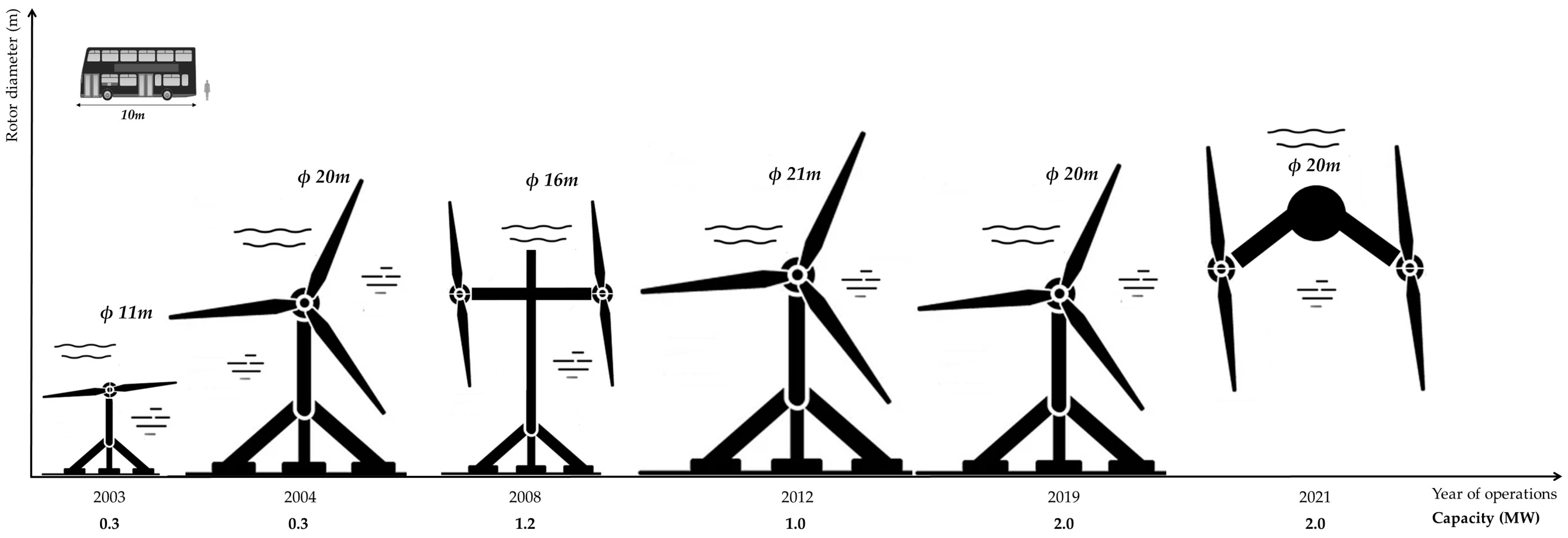
structural testing tidal energy structural integrity full-scale testing

1. Introduction

The total potential of tidal energy is predicted to be 3000 GW, and nearly 1000 GW is available in shallow waters [1]. As of the end of 2021, the cumulative installation of tidal stream technology that has been deployed in Europe since 2010 has reached 30.2 MW [2]. Since tidal energy can be predicted more accurately than some other renewable energy sources, tidal energy industries are expected to invest in large-scale projects to enhance sustainable electricity generation. To motivate the industry, several demonstration projects have been carried out to illustrate the feasibility of capturing the energy from the tides generated by sea currents. In this context, the tidal sector has made remarkable progress throughout the last two decades, and Figure 1 summarizes the size and capacity evaluation of tidal turbine deployments from 2003 to 2021. In addition to the increase in size, developers have come up with different design approaches to capture tidal energy, and these include new-generation floating and hubless tidal turbine systems. At the same time, developers have improved the efficiency of the tidal turbine systems without making significant changes to the rotor diameters. For instance, “HS 1000”, with a rotor diameter of 21 m, had a rated power of 1 MW in 2012, while “AR2000”, with a rotor diameter of 20 m, was capable of generating 2 MW in 2019 [3][4].
Figure 1. Size and capacity evaluation of tidal turbines.
Currently, advanced composite materials are employed by almost all manufacturers to fabricate turbine blades due to their numerous advantages, such as a high strength-to-weight ratio, durability, corrosion resistance and fatigue resistance, which enable them to withstand the severe and rigorous marine environment [5][6][7]. Moreover, the flexibility of composites provides designers with the ability to construct blades of complicated shapes and geometries, thereby optimizing the efficiency of the diverse types of TEC. Of the different types of TEC, horizontal-axis (axial flow) tidal turbines have achieved a technology readiness level of 8, signaling the maturity of the axial flow tidal energy sector around the world [8]. It justifies the deployment of 86% of axial flow tidal turbine projects around the world compared to the other types of TEC [9]. These horizontal-axis tidal turbine blades are exposed to harsh environmental conditions and high hydrodynamic loading on the blades in the operating phase, and their designed life expectancy of up to 25 years is questionable [10][11]. Subsequently, in order to assure safe operation of the structural components of the tidal turbine system, the turbine blades take precedence. The static loads acting on the tidal turbine blades are much higher than the equivalent-length wind turbine blades, and the spar caps should be strengthened, as they are crucial members to bear most of the loadings of the turbine [11].  Therefore, designing a horizontal-axis tidal turbine is a challenging task for designers, and they need to consider several factors during the design process. This causes overdesigning of the tidal turbine systems, leading to higher-cost drivers at the manufacturing and installation phases. High costs can limit investments in the tidal energy industry. Furthermore, some critical failures of the tidal turbine systems also slow down the development of the industry. For instance, a 12-bladed hubless tidal turbine, which was deployed by OpenHydro, failed due to the unexpected sea currents in 2009, and this emphasizes the importance of accurately predicting the loading conditions that act on the tidal blades during structural testing [12]. Therefore, structural testing to reduce uncertainties and risk is required to improve the reliability of tidal turbine blades so that investors can make their decisions effectively. In addition, the structural testing program should validate the structural integrity and ensure economic sustainability in the manufacturing and operational phases of tidal turbine systems.

2. Structural Testing Procedure

In operation, horizontal-axis tidal turbine blades are loaded throughout their span, while being supported at their roots during rotation. Therefore, the most suitable approach to studying the structural behaviour of blades is to consider one blade as a cantilevered section loaded in bending [13]. Blades for tidal turbines are generally shorter and stiffer than blades for an equivalent-capacity wind turbine. Furthermore, multiple loading points are required to closely replicate the shear force and bending moment distributions experienced along the length of tidal turbine blades while in service. These loads are typically applied in the mechanical/structural testing of tidal turbine blades in the laboratory through multiple hydraulic actuators applying loads simultaneously. In this context, it requires a substantial capital investment to build a large structural testing facility capable of undertaking the full-scale structural testing of tidal turbine blades. This has resulted in a limited number of facilities being available around the world. University of Galway, The University of Edinburgh, National Renewable Energy Laboratory (NREL), French Institute for Ocean Science (IFREMER—Institut Français de Recherche pour l’Exploitation de la Mer), BLAEST in Demark and Technical University of Denmark have been identified as some of the leading institutions that have large enough structural testing facilities to conduct full-scale tidal turbine blades for testing [14][15][16][17]. An image of the schematic facility at University of Galway, including the test bed, test frame, load introduction fixtures and some of the equipment used, is shown in Figure 2.
Figure 2. Structural testing facility at the University of Galway for tidal turbine blades. Adapted from [14].
The structural testing procedure of TECs should be aligned with DNVGL-ST-0164 and IEC DTS 62600–3 standard procedures to meet the regulations and safety standards. Therefore, the cantilevered blade, as shown in Figure 2, is subjected to dynamic, static, fatigue and residual strength testing to identify the structural integrity and reliability of tidal turbine blades. In addition, the mass and the center of gravity of the blade should also be measured as part of the testing procedure. In this context, the procedures, equipment and instrumentations used for these tests are vital in ensuring that the requirements mentioned in the standards are met.
Under the testing procedure, all critical regions of the blade should be tested in accordance with predetermined loading conditions. To estimate the testing loads, hydrodynamic loadings and environmental conditions at the chosen deployment site must be considered. During testing, particular attention should be given to the parts that have the lowest safety factors applied in their design against buckling, fatigue life and strength. Similarly, the blade’s sections attached to hydrodynamic braking systems, local reinforcements or any other special design features should be tested to identify their structural integrity. These critical sections of the blade and safety factors can be identified based on the design calculations and should be tested accordingly [18][19].

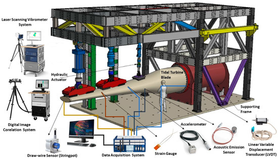
2.1. Blade Set-Up and Installation

Ensuring that the blade is loaded correctly is critical to carrying out successful testing. To represent the operating conditions of the turbine, all targeted regions should be substantially loaded [18][19]. To achieve this, the blade must be attached to the test bed and the load must be applied along the length of the blade. Therefore, a support frame to connect the blade to the test bed and load introduction fixtures (loading saddles/pads) should be designed and fabricated accordingly. Figure 2 shows the custom support frame and load introduction saddles required for testing a tidal blade. The cost of design and fabrication of these fixtures must be accounted for in the test budget. The features of the loading mechanism depend on the loading points of the blade, and estimated flapwise and edgewise loading requirements of both static and fatigue testing. In addition, the process of attaching the blade to the test rig and defining the test procedure is very important for the structural testing of tidal turbine blades. The features of the loading mechanism depend on the loading points of the blade and the estimated flapwise and edgewise loading requirements of both static and fatigue testing. In addition, the process of attaching the blade to the test rig and defining the test procedure is very important for the structural testing of tidal turbine blades.
During testing, forces, deflections, strains and accelerations may be recorded, since they are all key parameters that must be understood in any structural test program. The acceleration of the blade after impact is used to identify the natural frequency of the blade, which is also a fundamental property that should be measured in every test program. Some of the equipment and instrumentations that can be used to conduct and monitor the structural testing of tidal turbine blades have been highlighted in Figure 2. Each actuator contains a load and deflection sensor to monitor the loading at each location along the blade. Strain gauges are used to measure the strains at predefined locations along the blade and they may also be used on the test frame to measure its deflection. Draw-wire sensors (“stringpots”), and linear variable displacement transducers (LVDTs) measure the deflections at key locations. Laser scanning vibrometers (LSVs) and accelerometers may be used to measure the acceleration of the blade at various locations. A digital image correlation (DIC) system may be used to monitor strain during testing. A DIC system measures full field strain and displacement of a surface (as opposed to a strain gauge, which gives strain at a single location). It should be noted that the DIC is generally not used to test the whole surface of the blade due to limitations to the maximum measurement area and surface curvature. However, it can be used to effectively measure deformations of the critical areas of the turbine blades. A 3D laser scanner can be used to scan the blade and test set-up before and during testing, so a full as-built 3D geometry can be captured, as well as a 3D point cloud of the blade under loading conditions. Acoustic emission sensors are used to record sounds that might indicate damage occurring during the testing. In addition, Table 1 discusses the working principles of the instruments used for structural testing in brief. These sensors should be connected to the data acquisition (DAQ) system before starting the testing, and system checking must be undertaken to ensure the responses of the transducers. The positions of the strain gauges, accelerometers, stringpots, acoustic emission sensors and LVDTs are decided based on the testing requirements and the experience of the testing technicians.
Table 1. Working principles of the equipment and transducers used for the structural testing of tidal turbine blades.

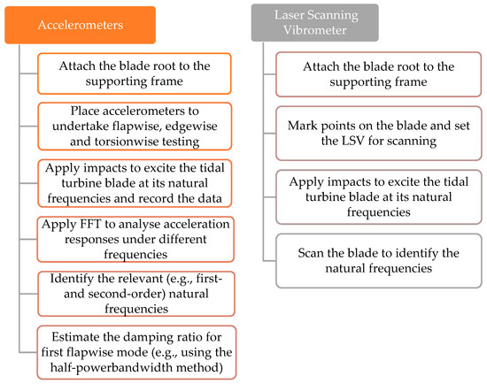
2.2. Dynamic Testing

Dynamic testing is carried out to determine the relevant natural frequencies, mode shapes and damping ratios of the blade. For this test, the blade should be connected to the test bed, but it should not have other equipment such as load introduction fixtures attached. For that, piezoelectric accelerometers or LSV may be utilized with an impulse hammer under free-damped vibration to monitor the acceleration responses in different locations of the blade. Then, responses are analysed based on the fast Fourier transform (FFT) algorithm to obtain the dynamic properties of the blade. Figure 3 summarizes the steps used to perform dynamic testing using accelerometers and LSV relevant to the DNVGL-ST-0164 and IEC 62600–3 standards. According to the DNVGL-ST0164 standard, it is not required to estimate the second-order flapwise mode shape, since the hydrodynamic damping acting on the tidal turbine is much higher compared to the aerodynamic damping on wind turbine blades [19]. The dynamic behaviour of the blade is important, as the measured value can be compared to the value predicted by the design to validate the design. Furthermore, changes in dynamic behaviour over the course of testing indicate that a change in the structural response of the blade has occurred due to damage or a change in the boundary conditions of the blade.
Figure 3. Steps for evaluating dynamic properties of tidal turbine blade [18][19][26].

2.3. Static Testing

A static test procedure for tidal turbine blades, which is in accordance with [18][19], is given in Figure 4. The target test loads in this procedure should represent extreme loading conditions in the following orientations:
  • Flapwise direction from pressure side to suction side;
  • Flapwise direction from suction side to pressure side;
  • Edgewise direction from trailing edge towards leading edge;
  • Edgewise direction from leading edge towards trailing edge;
  • Torsion-only stiffness distribution (this can be neglected if the torsional extreme loadings are not critical for the blade design.) [19].

Energies 16 04061 g010 550

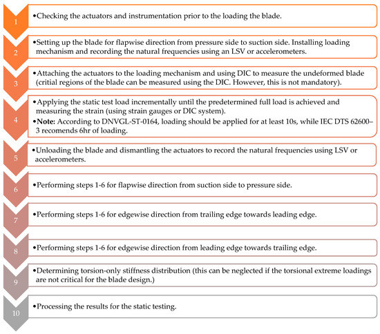
Figure 4. Static testing procedure for tidal turbine blades [18][19].

The edgewise extreme loading conditions can be omitted if they are not critical for the blade design. Dynamic testing will be carried out before and after all static and fatigue tests. The dynamic tests should be carried out without the actuators connected and with and without the load introduction saddles connected. Subsequently, the tests should be performed intermittently during testing to ensure no damage has occurred to the blade. In addition, the use of acoustic emission sensors enables the detection of fibre breaks, cracking and delamination in their early stages. Consequently, it can provide a platform to observe damage propagation of the tidal turbine blade during testing [18][19].

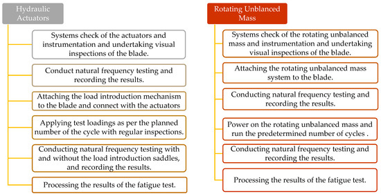
2.4. Fatigue Testing

Hydraulic actuators and unbalanced rotating mass mechanisms can be used to conduct fatigue testing for the tidal turbine blades. Figure 5 represents the testing procedure for both hydraulic actuators and unbalanced rotating mass systems.
Figure 5. Standard fatigue testing procedure for tidal turbine blades [18][19].

2.5. Residual Strength Testing

Both dynamic and static test results are used to undertake the residual strength testing of the tidal turbine blades. Therefore, static and dynamic testing should be undertaken again. During the testing programme, some regions of the blade may experience damage, and this damage should be assessed to identify any influence on the structural performance of the blade [18][19].

References

  1. Lemonis, G. Wave and Tidal Energy Conversion. Encycl. Energy 2004, 7, 385–396.
  2. Ocean Energy Europe. Ocean Energy Europe Ocean Energy Key Trends and Statistics 2021; Ocean Energy Europe: Belgium, Brussels, 2022.
  3. Renewable Energy from Tidal Currents; ANDRITZ HYDRO Hammerfest: Graz, Austria, 2012; pp. 6–10.
  4. Zhou, Z.; Scuiller, F.; Charpentier, J.-F.; Benbouzid, M.; Tang, T.; An, T.T. An Up-to-Date Review of Large Marine Tidal Current Turbine Technologies; IEEE: Piscataway, NJ, USA, 2014.
  5. Rajak, D.K.; Pagar, D.D.; Kumar, R.; Pruncu, C.I. Recent Progress of Reinforcement Materials: A Comprehensive Overview of Composite Materials. J. Mater. Res. Technol. 2019, 8, 6354–6374.
  6. Hasan, M.; Zhao, J.; Jiang, Z. Micromanufacturing of Composite Materials: A Review. Int. J. Extrem. Manuf. 2019, 1, 012004.
  7. Hsissou, R.; Seghiri, R.; Benzekri, Z.; Hilali, M.; Rafik, M.; Elharfi, A. Polymer Composite Materials: A Comprehensive Review. Compos. Struct. 2021, 262, 113640.
  8. Davide, M.; Andreas, U.; Riccardo, M.; Joint Research Centre (European Commission). JRC Ocean Energy Status Report Technology, Market and Economic Aspects of Ocean Energy in Europe: 2016 Edition; Publications Office: Luxembourg, 2016.
  9. Walker, S.; Thies, P.R. A Review of Component and System Reliability in Tidal Turbine Deployments. Renew. Sustain. Energy Rev. 2021, 151, 111495.
  10. Yu, G.Q.; Ren, Y.R.; Zhang, T.T.; Xiao, W.S.; Jiang, H.Y. Hashin Failure Theory Based Damage Assessment Methodology of Composite Tidal Turbine Blades and Implications for the Blade Design. China Ocean. Eng. 2018, 32, 216–225.
  11. Chen, L.; Lam, W.H. A Review of Survivability and Remedial Actions of Tidal Current Turbines. Renew. Sustain. Energy Rev. 2014, 43, 891–900.
  12. Failed Tidal Turbine Explained at Symposium. Available online: https://www.cbc.ca/news/canada/nova-scotia/failed-tidal-turbine-explained-at-symposium-1.1075510 (accessed on 24 March 2023).
  13. Murray, R. Passively Adaptive Tidal Turbine Blades: Design Methodology and Experimental Testing; Elsevier: Amsterdam, The Netherlands, 2016.
  14. Finnegan, W.; Jiang, Y.; Meier, P.; Hung, L.C.; Fagan, E.; Wallace, F.; Glennon, C.; Flanagan, M.; Flanagan, T.; Goggins, J. Numerical Modelling, Manufacture and Structural Testing of a Full-Scale 1 MW Tidal Turbine Blade. Ocean Eng. 2022, 266, 112717.
  15. FastBlade-World’s First Regenerative Fatigue Test Facility. Available online: https://www.fastblade.eng.ed.ac.uk/ (accessed on 7 March 2023).
  16. Test and Demonstration Facilities for Wind Energy Needed to Promote a Competitive Wind Industry in Denmark; MEGAVIND: Langebrogade, Denmark, 2016.
  17. Davies, P.; Dumergue, N.; Arhant, M.; Nicolas, E.; Paboeuf, S.; Mayorga, P. Material and Structural Testing to Improve Composite Tidal Turbine Blade Reliability. Int. Mar. Energy J. 2022, 5, 57–65.
  18. IEC DTS 62600–3; Marine Energy-Wave, Tidal and Other Water Current Converters-Part 3: Measurement of Mechanical Loads. International Electrotechnical Commission: Geneva, Switzerland, 2019.
  19. DNVGL-ST-0164; Tidal Turbines. Det Norske Veritas Germanischer Lloyd: Oslo, Norway, 2015.
  20. Zipser, L.; Franke, H. Laser-Scanning Vibrometry for Ultrasonic Transducer Development. Sens. Actuators A Phys. 2004, 110, 264–268.
  21. McCormick, N.; Lord, J. Digital Image Correlation for Structural Measurements. Proc. Inst. Civ. Eng.-Civ. Eng. 2012, 165, 185–190.
  22. Niu, W.; Fang, L.; Xu, L.; Li, X.; Huo, R.; Guo, D.; Qi, Z.; Niu, W.; Fang, L.; Xu, L.; et al. Summary of Research Status and Application of MEMS Accelerometers. J. Comput. Commun. 2018, 6, 215–221.
  23. Tutak, P. Application of Strain Gauges in Measurements of Strain Distribution in Complex Objects. JACSM 2014, 6, 135.
  24. Qian, Z.; Fan, Y.; Lu, Z. Application of Draw-Wire Displacement Sensors on Structural Health Monitoring of Jiangyin Bridge. In Proceedings of the Nondestructive Evaluation and Health Monitoring of Aerospace Materials, Composites, and Civil Infrastructure V, San Diego, CA, USA, 20 March 2006; Volume 6176.
  25. He, Y.; Li, M.; Meng, Z.; Chen, S.; Huang, S.; Hu, Y.; Zou, X. An Overview of Acoustic Emission Inspection and Monitoring Technology in the Key Components of Renewable Energy Systems. Mech. Syst. Signal Process. 2021, 148, 107146.
  26. Jiang, Y.; Finnegan, W.; Vanhari, A.K.; Meier, P.; Fagan, E.; Goggins, J. Natural Frequency Measurement of a 13-M Wind Turbine Blade Using Different Techniques. In Proceedings of the Civil Engineering Research in Ireland, Cork, Ireland, 27–28 August 2020; pp. 265–270.
More
Information
Contributors MDPI registered users' name will be linked to their SciProfiles pages. To register with us, please refer to https://encyclopedia.pub/register : , , ,
View Times: 396
Revisions: 2 times (View History)
Update Date: 03 Jul 2023
1000/1000